Introduction
The computer aided design assignment helped me understand the basics of 2D and 3D designing. I learned the difference between raster and vector images and how to work with both types. Through this assignment, I explored how images can be created, edited, and converted using design software. I also practiced making shapes, patterns, and text in 2D design tools. In addition, I got an introduction to basic 3D modeling concepts. Overall, this assignment helped me learn how different 2D and 3D software tools are used in digital design.
Difference between 2D and 3D
| 2D |
3D |
| 2D designs have only two dimensions-length and width. |
while 3D designs have three dimensions-length, width, and height. |
| 2D is mainly used for drawings, layouts, logos, and technical sketches. |
3D is used for product design, mechanical parts, and realistic models. |
| In 2D, we edit shapes and lines. |
in 3D, we can add thickness, cuts, holes, and features to create a complete object. |
| 2D is done using software like Inkscape, Illustrator, Gimp, RdWorks. |
3D is done using softwares like Solidworks, Freecad, Fusion360, Blender. |
Selection of 2D software
Why I choose Inkscape for 2d designing?
- First, Inkscape is highly suitable for creating vector-based designs, which are required for laser cutting, vinyl cutting. Vector files ensure precise cutting paths without loss of quality. This was important for my assignments involving laser cutting and creating accurate profiles.
- Second, Inkscape supports multiple file formats such as SVG, DXF, and PDF, which are compatible with laser cutting machines and other fabrication tools. This made it easy to export designs directly for fabrication without conversion issues.
- Third, Inkscape is free and open-source, making it accessible and practical for continuous use in Fab Academy and future projects.
Selection of 3D software
Why I choose Solidworks for 3D designing?
- One of the main reasons for selecting SolidWorks is its parametric design capability, which allows modification of dimensions easily. This is very important in digital fabrication because designs often require adjustments based on material thickness, tolerance, and clearance.
- Second, SolidWorks provides highly accurate and precise modeling tools, which are essential for designing functional components such as mechanical parts, assemblies, and movable mechanisms.
- SolidWorks supports export formats such as STL, STEP, and DXF, which are compatible with 3D printing, CNC machining, and laser cutting.
Conclusion
I selected Inkscape for 2D design because it provides precise vector editing, compatibility with digital fabrication machines, and ease of use. I selected SolidWorks for 3D design because of its parametric modeling capability, high precision, and suitability for designing functional mechanical components. Both software tools are well-suited for digital fabrication workflows and support efficient design, modification, and fabrication of components.
Inkscape
Inkscape is a 2D design software used to create logos, patterns, and simple graphic designs. It works with vector graphics, so designs can be resized without losing quality. We can draw shapes, add text, and use tools like union and intersection to make clean designs. Inkscape also allows importing raster images and converting them into vector graphics using tracing. It is free, open-source software.
 |
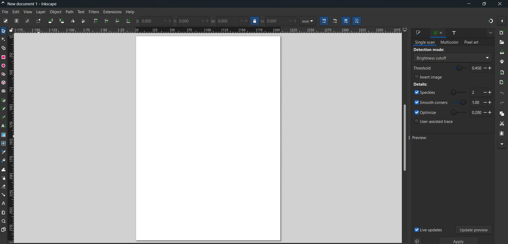 |
| So, first I opened Inkscape software |
and clicked on new document |
 |
 |
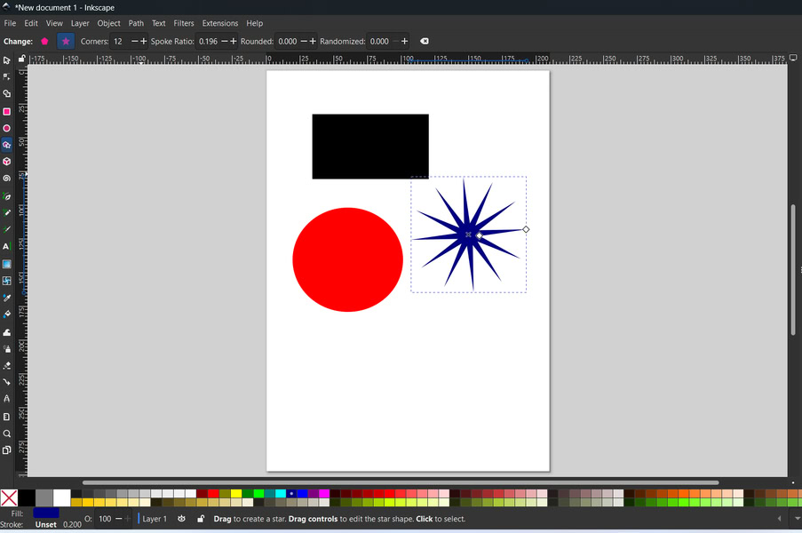
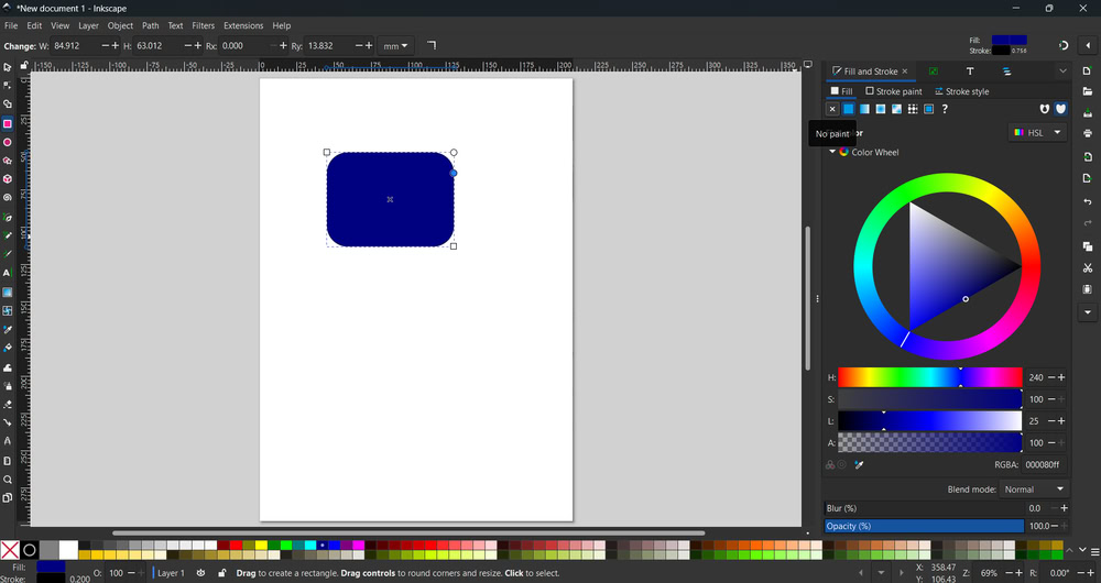
| First I learned Inkscape interface and how to drag and move shapes on the canvas. |
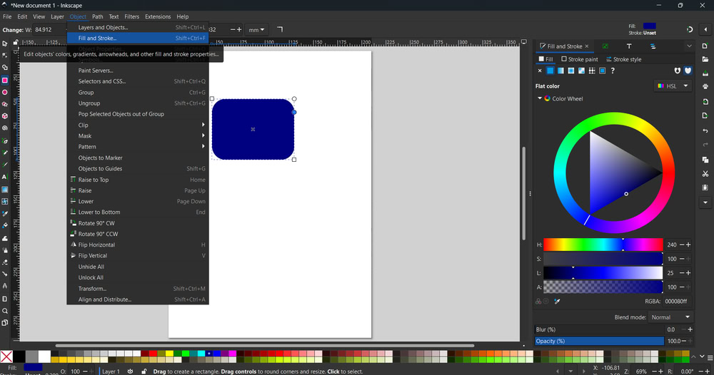
Then I select rectangle and Drew one rectangle on the workspace I gave rectangle blue colour using fill option After that There is a small circle on When you click on Rectangle So when I adjusted that circle the corners handles appears I made the corners rounded . Next I wanted To make only border instead of a filled box so I open Fill and stroke option |
 |
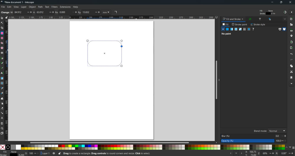 |
| The fill and stroke panel appeared on the right side of the screen |
In the fill tab I clicked on no paint option And the rectangle become colourless |
 |
 |
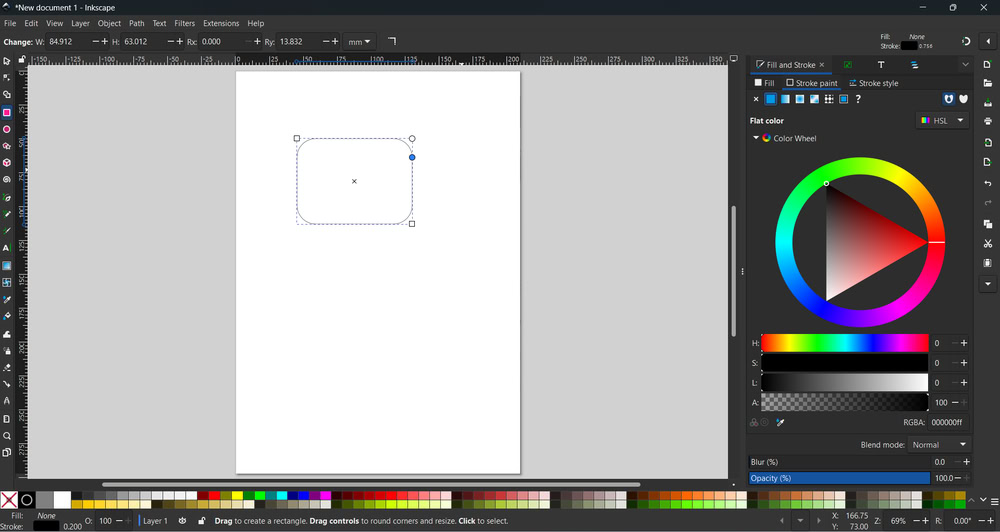
| Then I clicked on stroke paint option.In stroke paint I selected the flat colour option to apply Colour to Border. |
After that I opened Stroke style tab. |
|
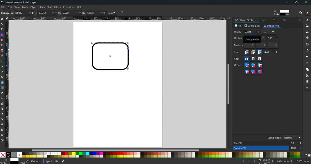
| In stroke style I increased the width And the border appeared clearly. As I increased the width more the border became Thicker. Finally this is how the final shape with rounded border was created step by step. |
|
Raster and Vector
Raster images are made up of very small dots called pixels. Each pixel has its own color, and together they form an image. Photographs and scanned images are common examples of raster graphics. Raster images show a lot of detail and look realistic. However, when we zoom in or enlarge a raster image, it becomes blurry or pixelated. Raster images are mainly used in photo editing, digital paintings, and images taken from cameras. Common raster file formats are JPG, PNG, and BMP
Vector images are created using lines, curves, and shapes based on mathematical formulas. They do not depend on pixels, so they can be resized without losing quality. Even when zoomed in, vector images remain clear and sharp. Vector graphics are easy to edit and modify. They are mostly used for logos, icons, diagrams, patterns, and technical drawings. Common vector file formats are SVG, AI, and DXF.
 |
 |
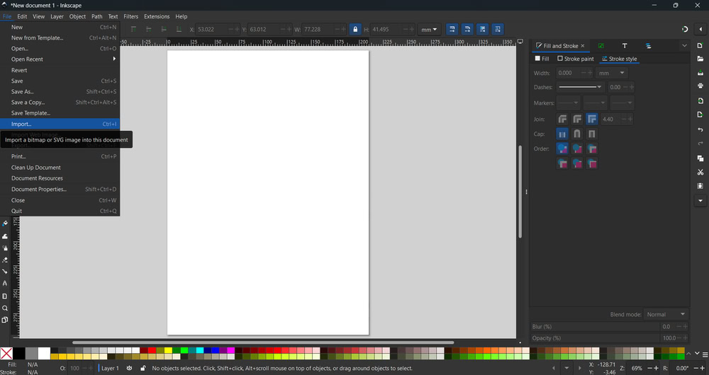
| I imported an image inkscape using the import option. |
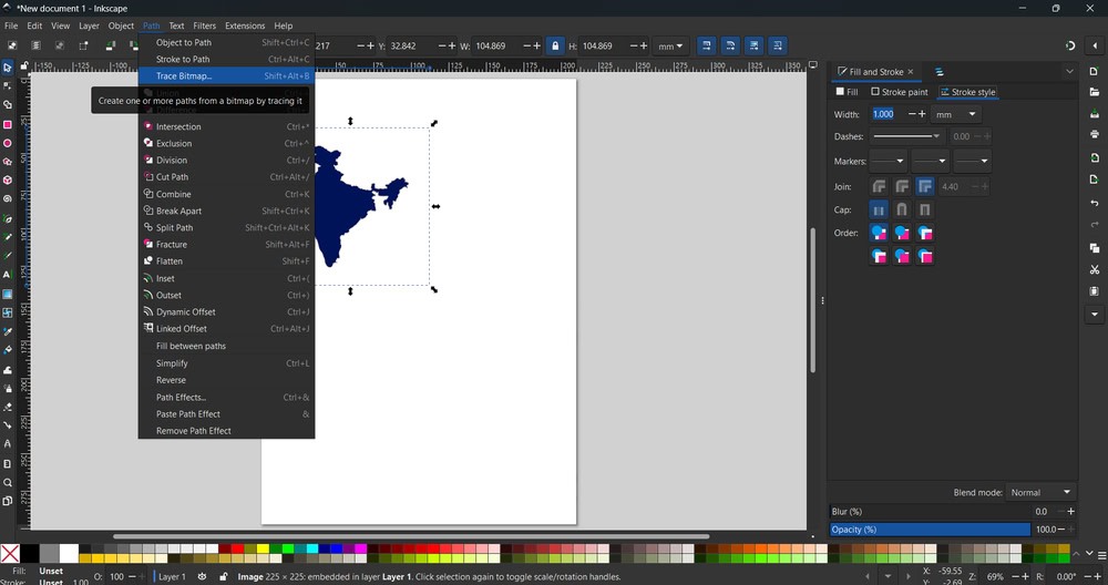
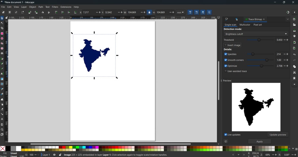
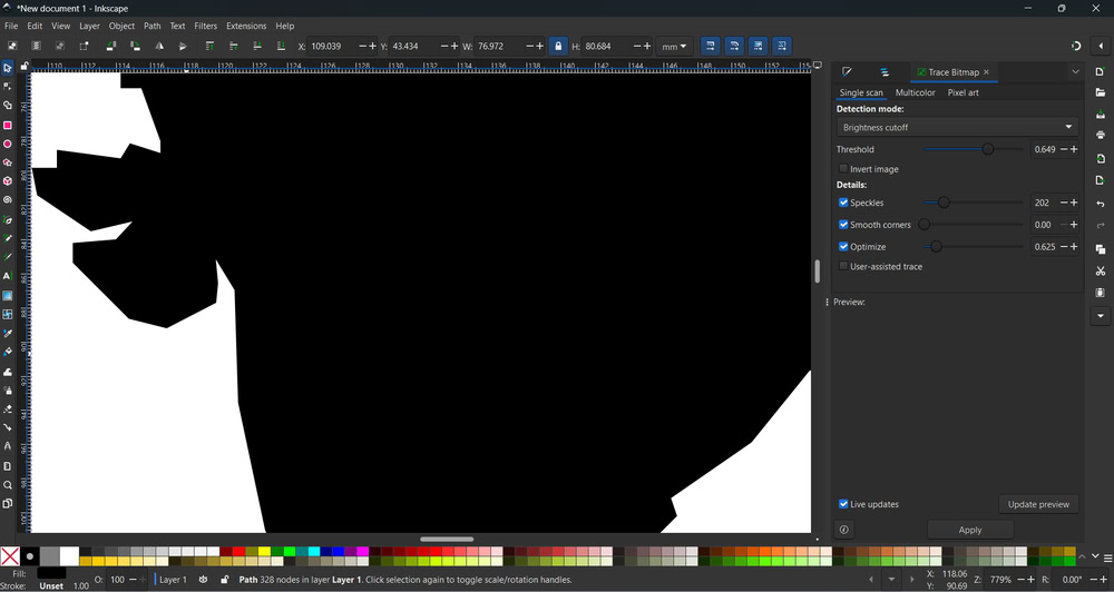
Then I clicked on trace bitmap option and clicked apply. |
 |
 |
| After that I got a traced image. |
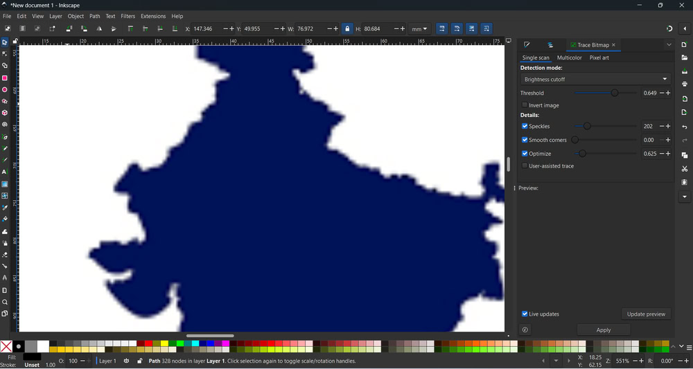
A raster image is made up of pixels, so it looks blurry when zoomed in. |
 |
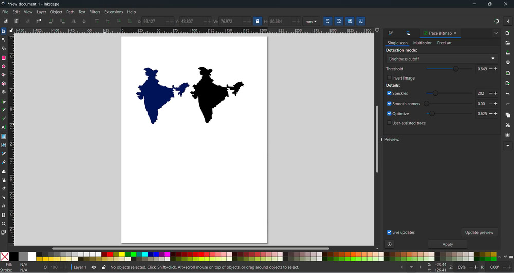 |
| A vector image is made up of lines and shapes, so it looks clear even when zoomed in. |
From this I learned the difference between raster images and vector images. |
Design
 |
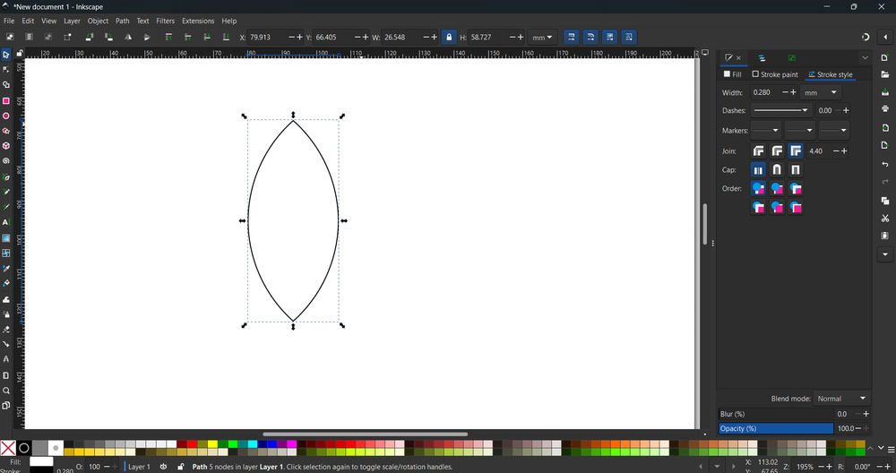 |
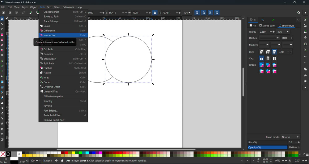
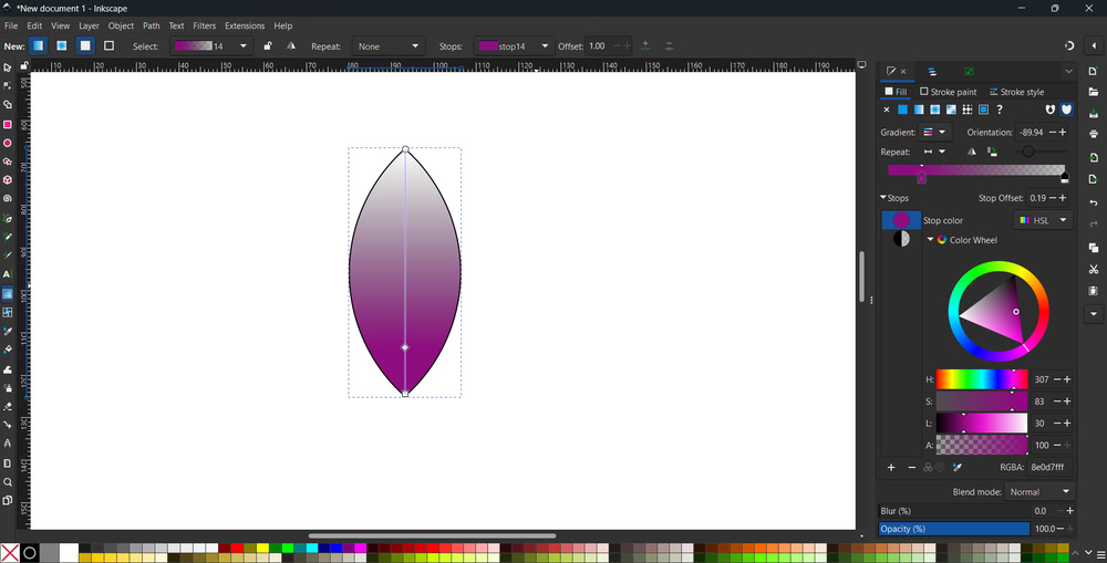
| I took two circles,selected both of them and clicked on the intersection option. |
So, after that I got petal shape. |
 |
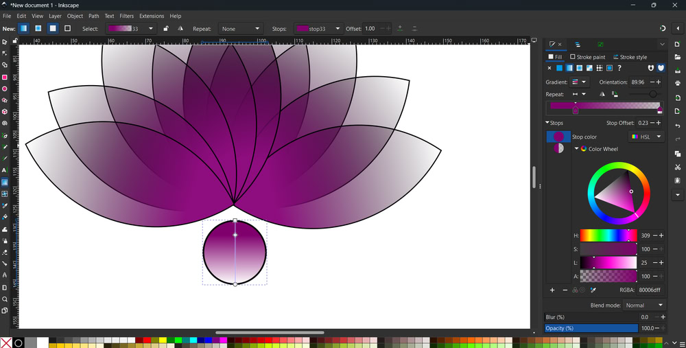
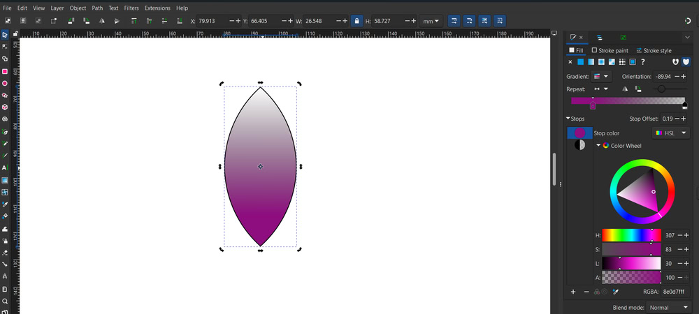 |
| Using the Gradient tool, I changed the direction of the color shading. |
When you double-click on the shape, the corners appear, so you can change the angle of the shape. |
 |
 |
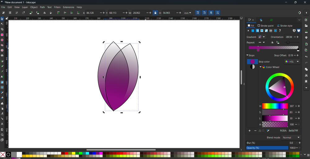
| I pressed ctrl + d to duplicate the petal and changed it's angle using side arrows on the petal. |
So the Structure started looking like this. |
 |
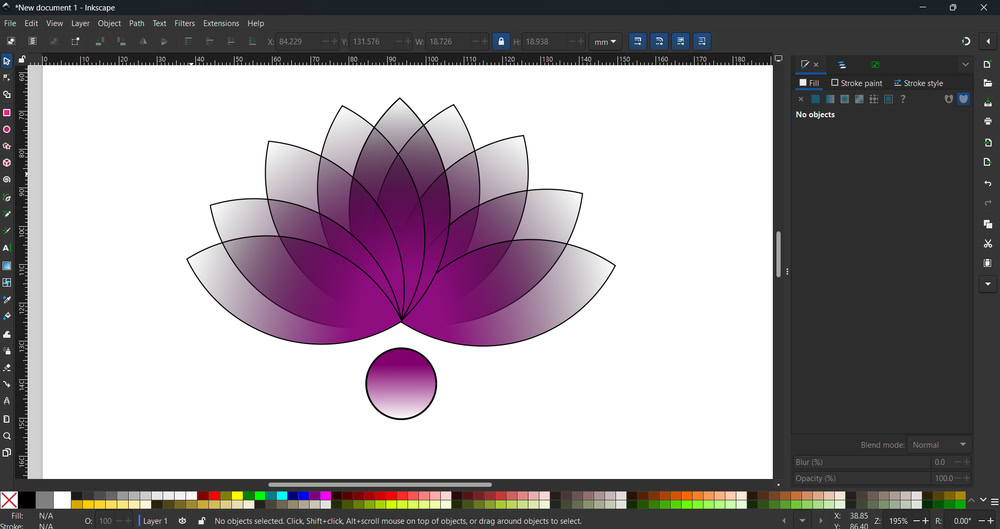 |
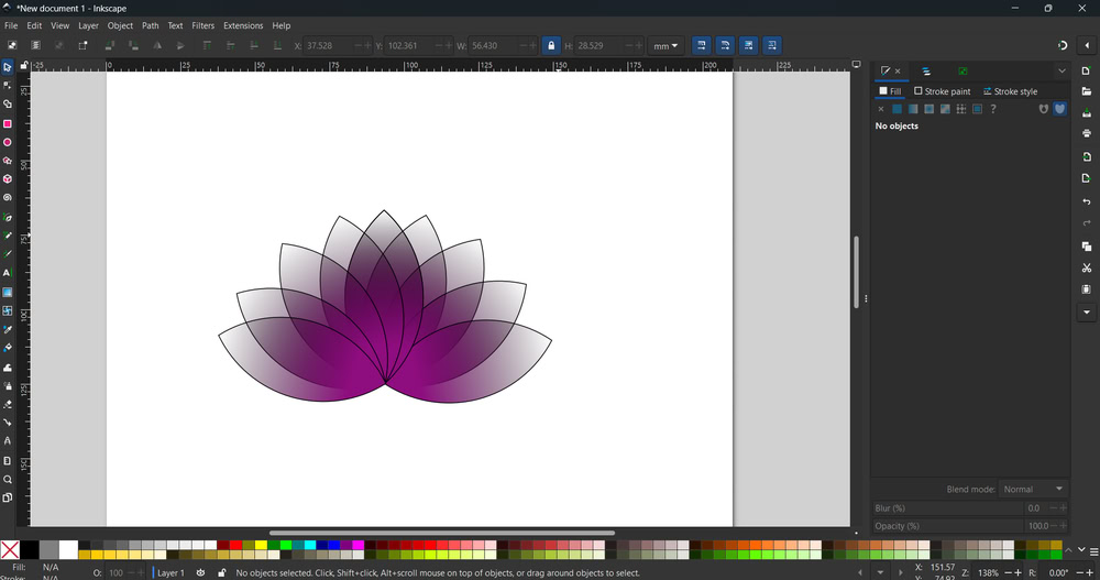
| Using the Gradient tool, I changed the direction of the color shading. |
So, my flower design is ready!!! |
Solidworks
SolidWorks is a 3D designing CAD software used for 3D modelling. It is mainly used to create 3D models of parts, components, and assemblies. The software provides many tools and options that help us design models easily and accurately. Using SolidWorks, we can convert our ideas into digital 3D models before making the actual product. It allows us to edit designs, change dimensions, and improve accuracy. SolidWorks is widely used in engineering and product design industries. It also helps in reducing errors by testing designs virtually. Overall, SolidWorks is a powerful and user-friendly software for 3D design and development.
 |
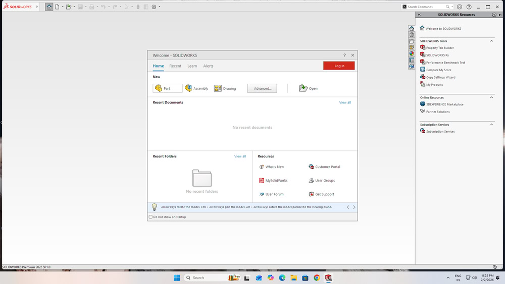 |
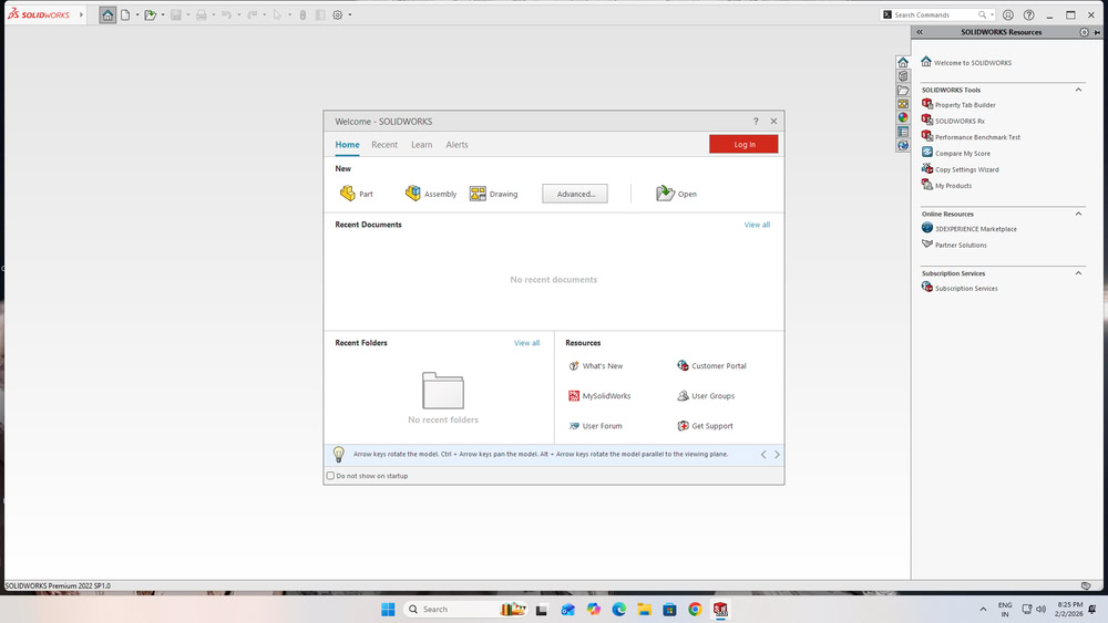
| First I opened Solidwork software. |
Then I clicked on part option. |
 |
 |
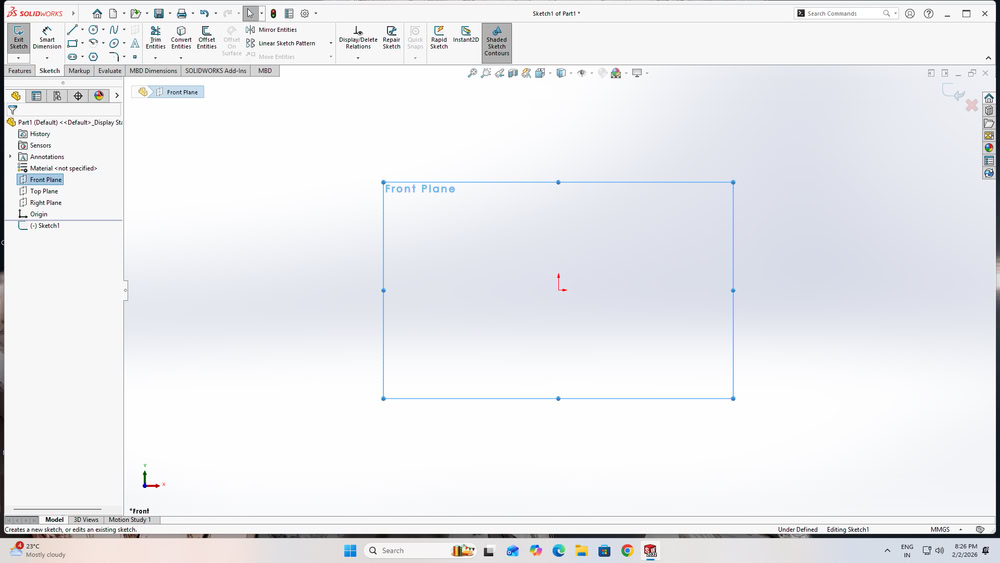
| Using front plane option, I select front plane. |
Then I took one circle from shapes. |
 |
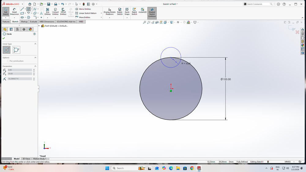 |
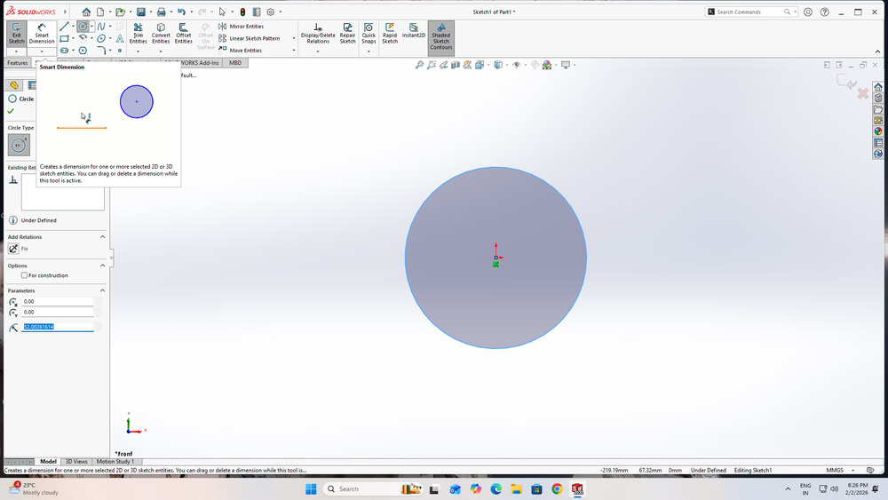
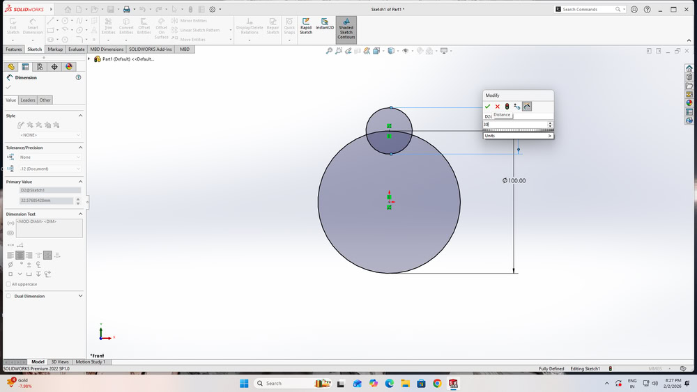
| First, I selected Smart Dimension and changed the dimensions of the main circle. |
Then, I drew another smaller circle on the top of the main circle as shown in the sketch |
 |
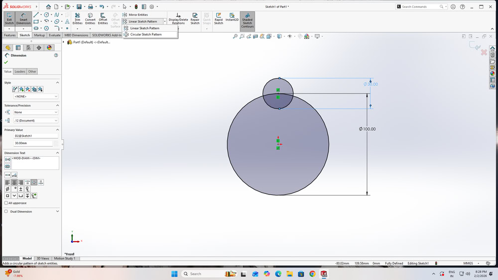 |
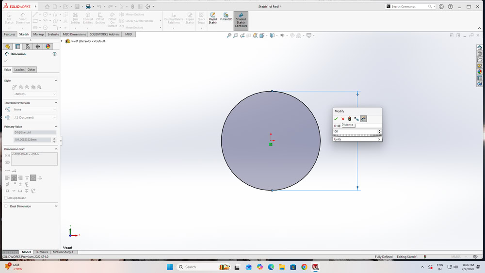
| I applied dimensions to the circle. |
In this way, I successfully modified the dimensions of both circles. |
 |
 |
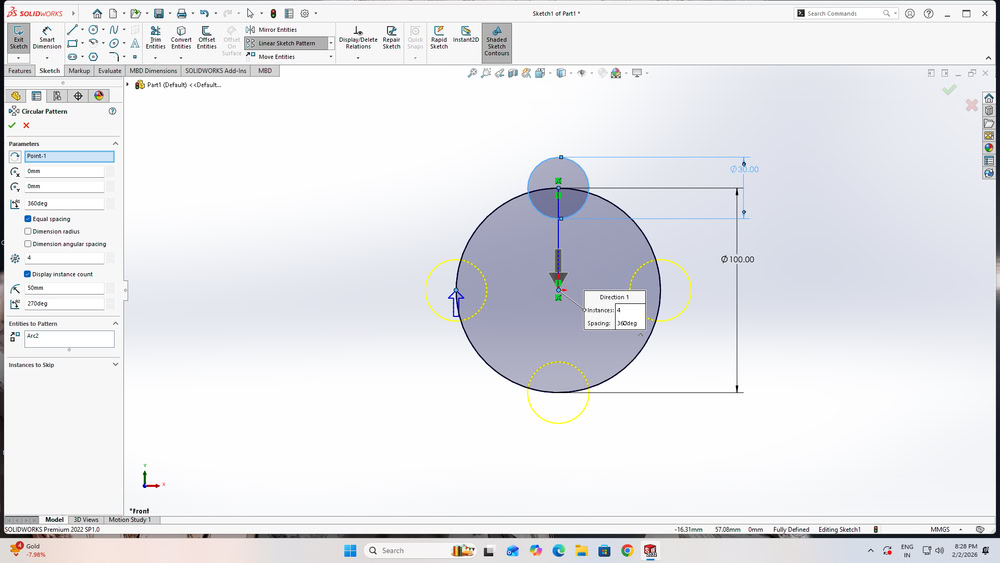
| After that, I saw the Linear Sketch Pattern option, and below it I chose the Circular Sketch Pattern option. |
I clicked on the smaller circle because I wanted to create multiple copies of it. |
 |
 |
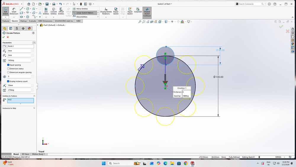
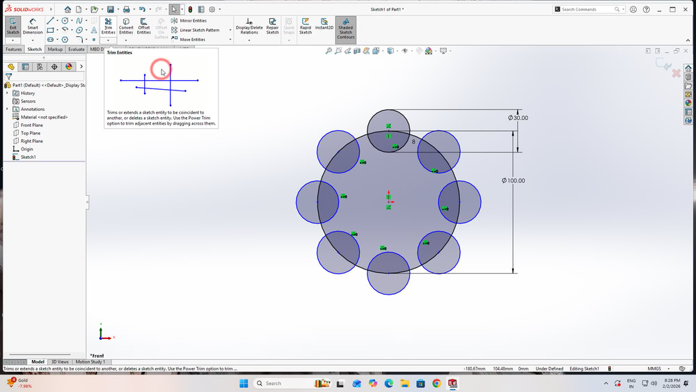
| I set the number of instances to 8, and the circular pattern was created. |
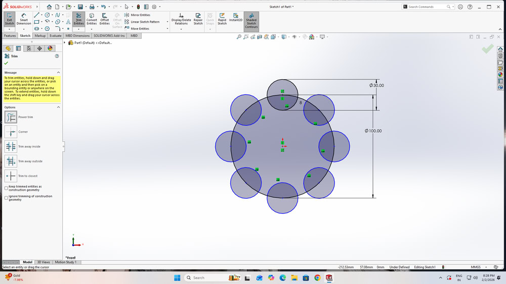
Next, I clicked on the Trim Entities option. |
 |
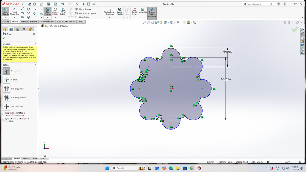 |
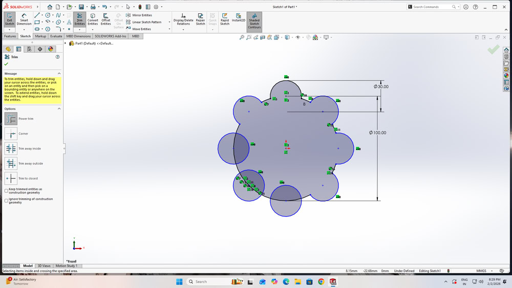
| After that I select Power Trim to remove the unwanted lines from the sketch. |
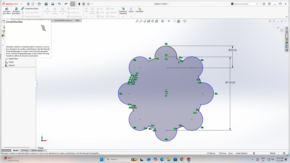
After cleaning the sketch, The sketch looks like this . |
 |
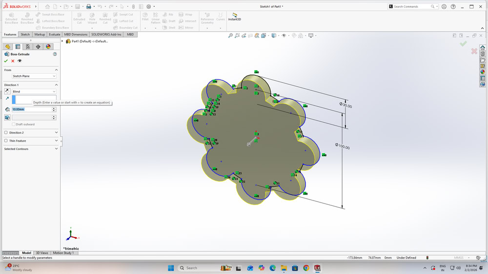 |
| I went to the Features tab and selected Extruded Boss/Base to extrude the sketch |
I gave an extrusion depth of 10 mm. |
 |
 |
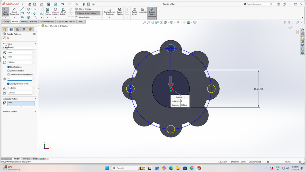
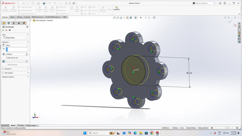
| After that, I again drew some circles according to my design requirements |
I select the Circular Sketch Pattern option and I set the number of circle instances as required for the design |
 |
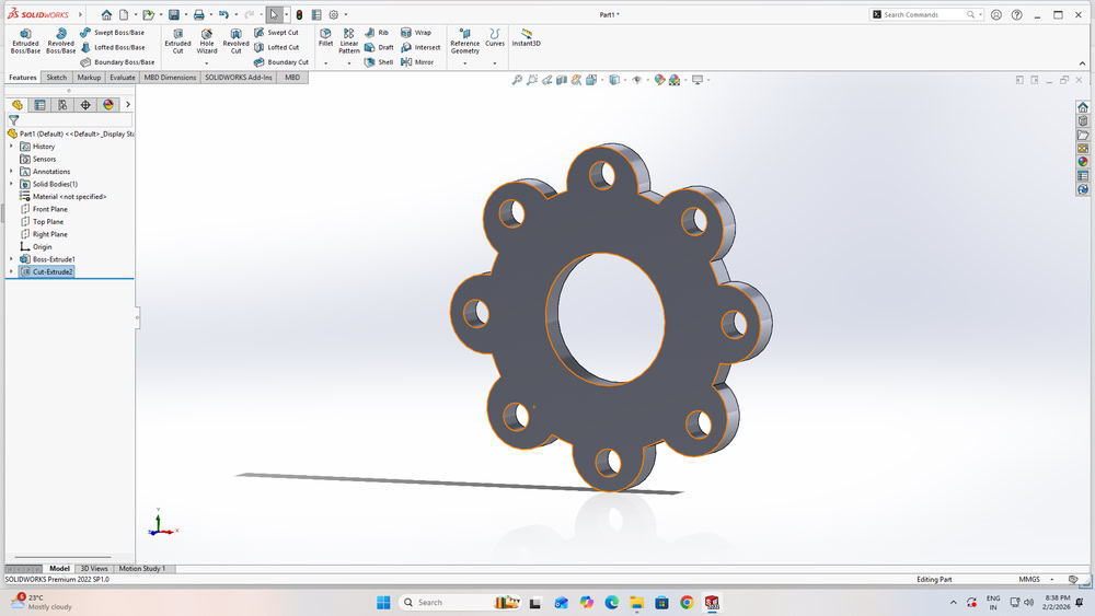 |
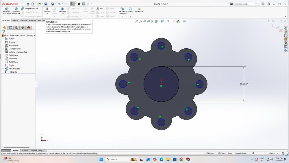
| Then, I selected the Extruded Cut option from the Features tab to remove material from the model and create the required holes. |
After completing the cut operation, the design looked as shown in the view. |
 |
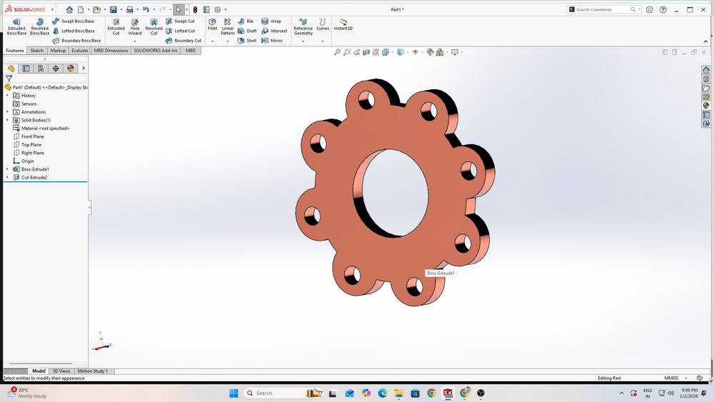 |
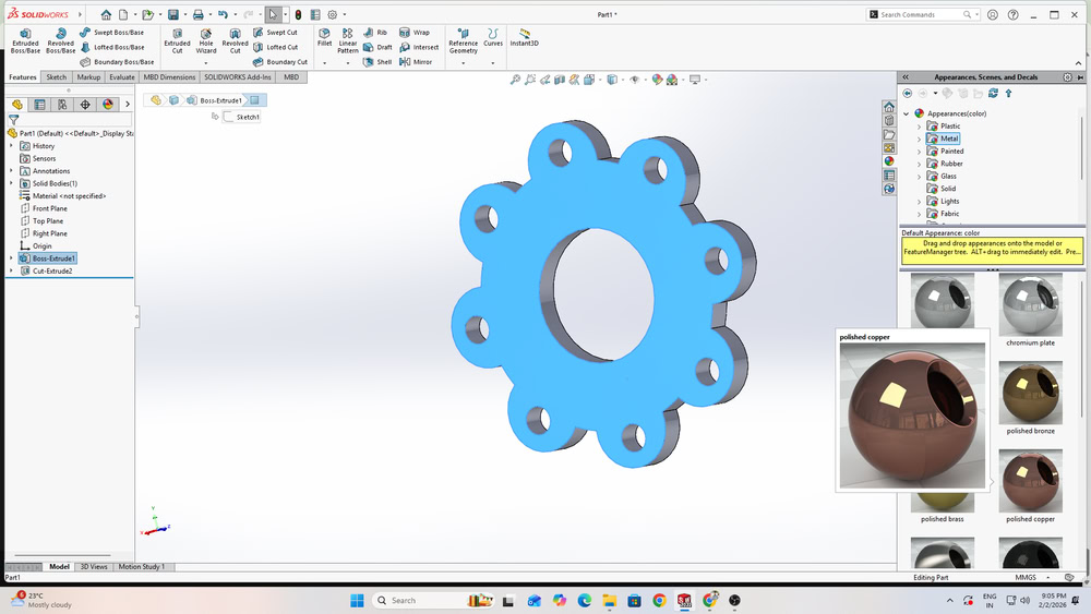
| While exploring the software further, I found the Appearances option, which allows different visual effects to be applied to the model. From this option, I selected the Polished Copper appearance |
I was successfully applied visual effect to my design. |
Image Compression
XnConvert
XnConvert is a simple software used for image editing and image conversion. It allows users to process many images at the same time. We can resize, rotate, crop, and compress images easily. The software supports many image file formats. It also provides options to rename files automatically. XnConvert saves time and makes image work easy.
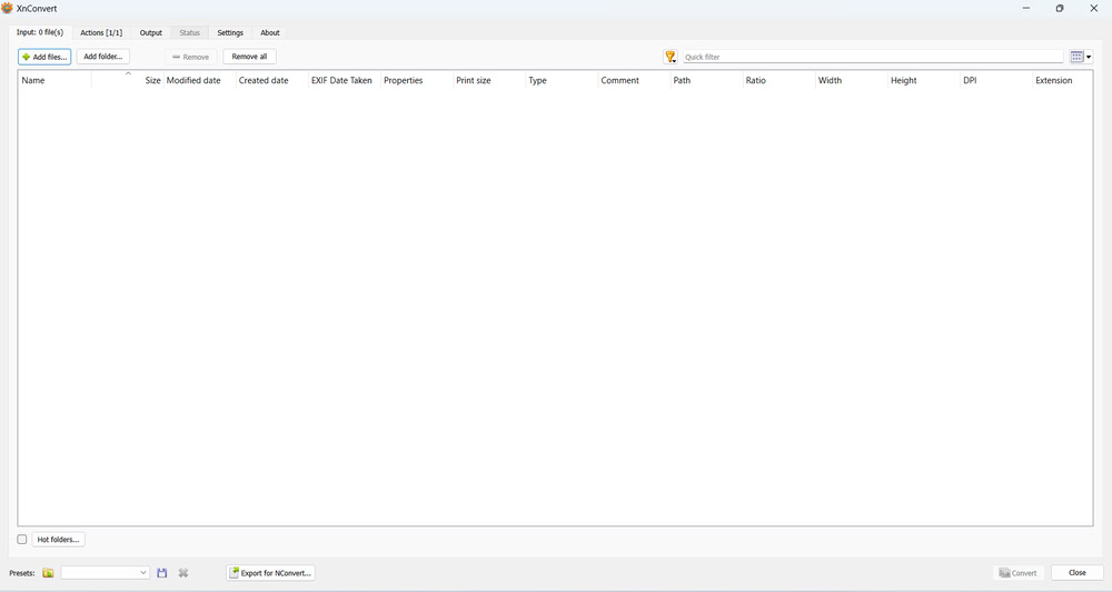
1.As a first step, I downloaded XnConvert on my system then clicked on add files option.
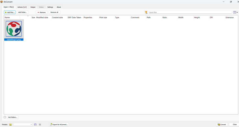
2.The file gets added successfully, you can add multiple files also.
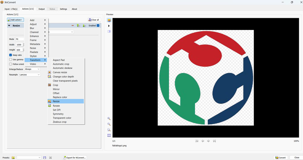
3.After that, in the Actions option, there is an Add Action option where I used the Resize option to resize the added file. I set the required width and height for the file.
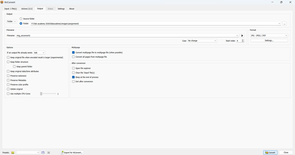
After that, in the Output section, I set the output folder where the converted images are saved. I also gave a name to the image and selected the file format I wanted. Then, I set the quality of the image and clicked on Convert. Finally, the image was saved in the selected folder.
Video compression:-
www.freeconvert.com
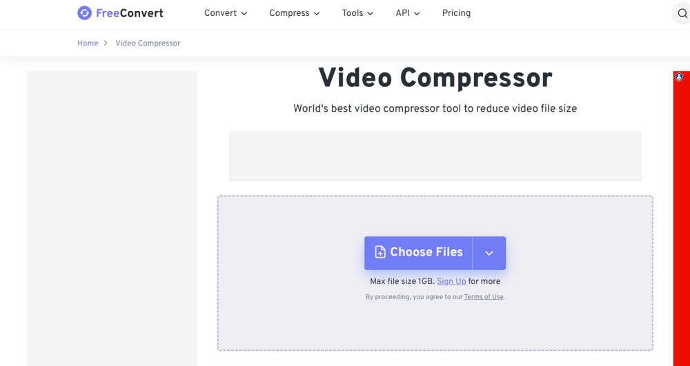
You just have to choose the file and selct your videos and again click on compress video and you are able to download compressed video.
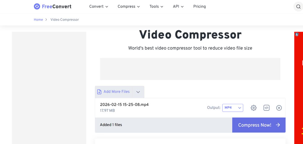
- It lets you reduce video file size online without installing software.
- It Supports formats like MP4, AVI, MKV, MOV, and more.
- You can also set the resolution depending upon your requirements.
All design files
Inkscape and Solidworks