Introduction
The System Integration assignment in Fab Academy focuses on combining all the individual parts of your final project into one complete and working system. In previous assignments, different elements such as electronics design, embedded programming, networking, mechanical design, input devices, output devices, molding and casting, and interface development were learned separately. In this assignment, all these modules are integrated together so they function as a single product or machine.
The main goal of this assignment is to demonstrate how hardware, software, electronics, mechanics, and communication systems interact with each other in a coordinated way. It involves connecting sensors, actuators, microcontrollers, power systems, communication protocols, and user interfaces into one unified workflow.
Individual assignment
Task:Design and document the system integration for your final project.
Hardware components used in this project:-
- xiao esp32c3
- 3V3 Relay
- OLED Display
- Push button 2 pin
- 2 pin connectors
- 3 pin connectors
- 4 pin connectors
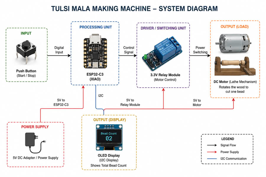
Working mechanism of my project is as follows:-
Push Button (Machine Control Input)
The push button acts as the main input device of the system. When the user presses the button, the signal is sent to the Seeed Studio XIAO ESP32-C3 microcontroller to control the machine operation. The button is used to start and stop the bead-making process during machining.
Relay Module (Motor Control System)
A 3.3V relay module is connected to the Seeed Studio XIAO ESP32-C3 and works as a switching device for the motor. When the push button is pressed, the microcontroller activates the relay, which turns ON the lathe motor. Pressing the button again turns OFF the motor after one wooden bead is completed.
Motor and Lathe Mechanism
The wooden stick is mounted on the rotating motor shaft similar to a lathe machine mechanism. When the motor rotates, the wood spins at high speed, allowing the user to shape and cut a single Tulsi bead manually. After one bead is formed, the machine is stopped for counting and further processing.
OLED Display (Bead Counting Output)
An OLED display connected through the I2C communication protocol is used as the output display device. Every time the machine completes one bead and the motor is stopped, the bead count increases automatically on the OLED screen. The display continuously shows the total number of Tulsi beads produced during the process.
Overall System Integration
In this system, the push button provides input to the microcontroller, the microcontroller controls the relay module, the relay operates the motor for bead formation, and the OLED display provides real-time bead count feedback. All electronic, mechanical, and embedded components work together as a single integrated system for semi-automatic Tulsi mala bead production.
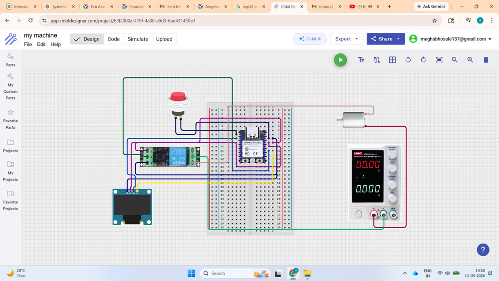
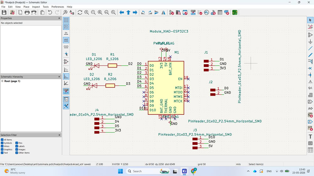
Circuit Diagram
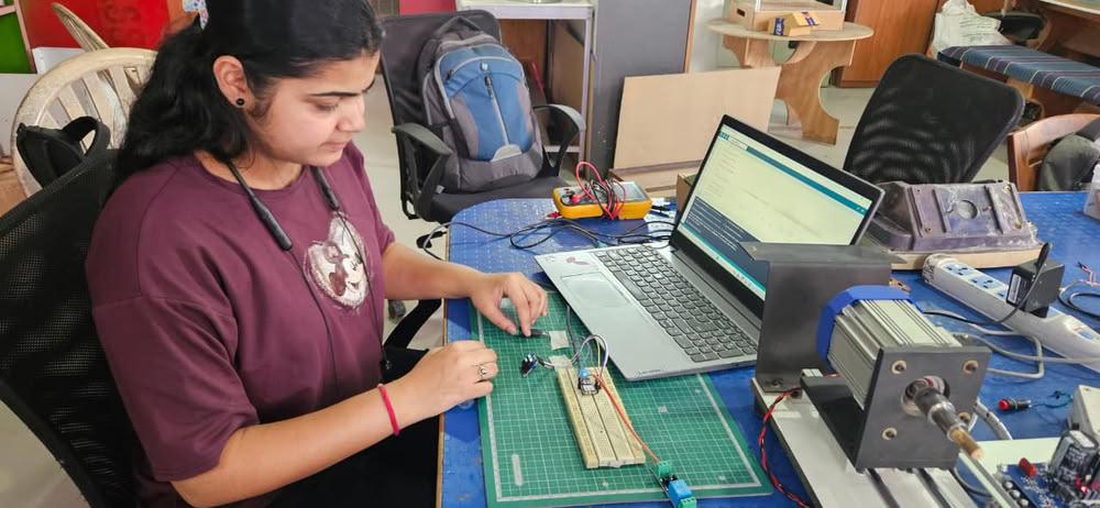
Testing Electronics
Components used for testing:-
- XIAO ESP32C3:- Used as the microcontroller for testing input/output logic.
- Relay:- Used to control external devices or switching operations through the microcontroller.
- Push Button:- Used as a manual input device for triggering actions and turns on/off motor.
- OLED Display:- Used to display the counter during bead making process.
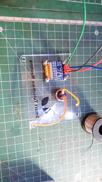
Testing process:-
Here is the testing counter:-
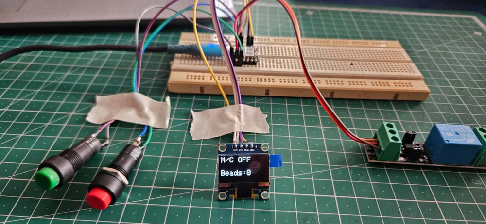
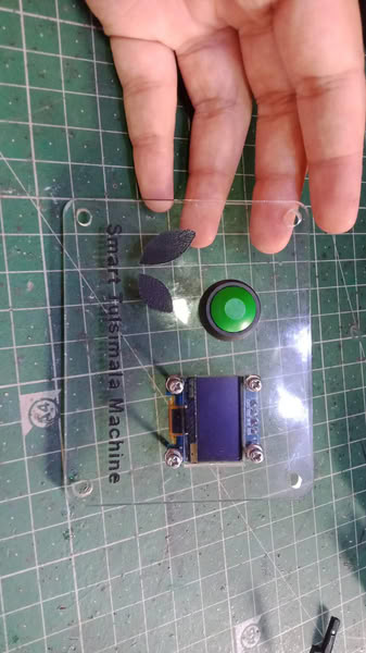
Here is another testing with single button
So, for easy handling of the machine, I used only single button for turning on and off the machine.
PCB Design:-
In the final project PCB making process, I designed the circuit in KiCad software by creating the schematic diagram.
I update it in the PCB editor.
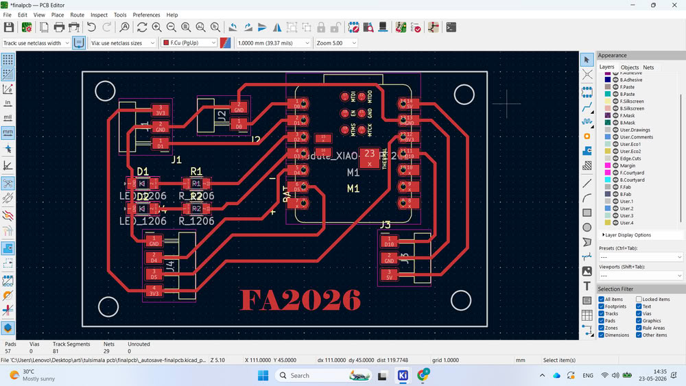
After completing the routing, I generated the Gerber files and PNG files. Then, I converted the PNG files into .rml format using Mods CE for PCB milling.
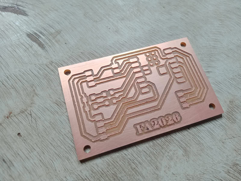
PCB Milling:-
here is the trace cut result
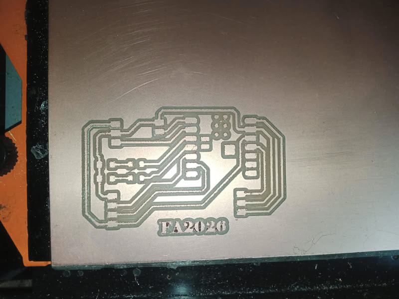
During the cutting process, I changed the milling bit from 1/64 inch to 1/32 inch for the edge cut.
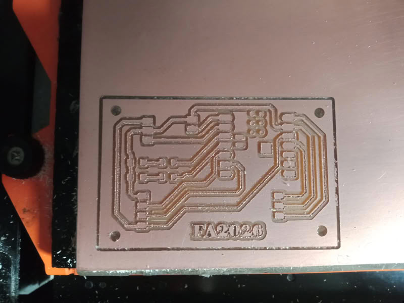
The PCB was cut properly.
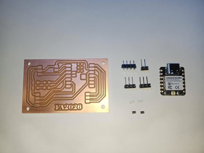
After that, I collected all the required components.
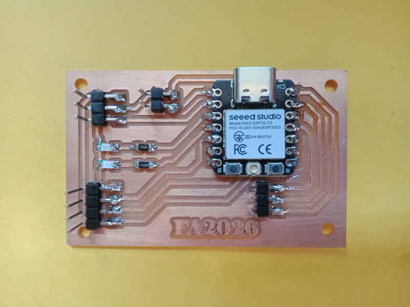
I carefully soldered them on the PCB.

3D designing:-
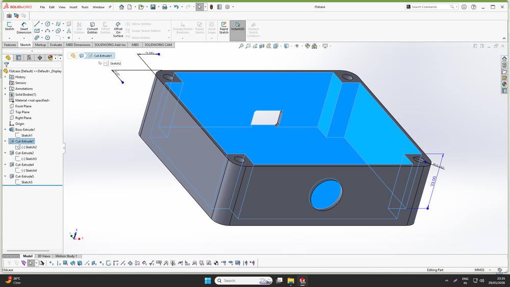
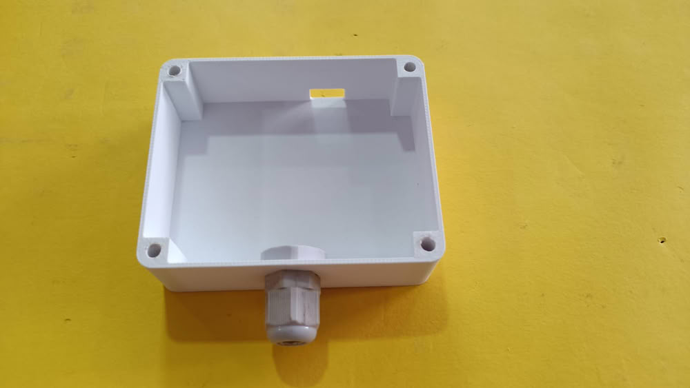
I designed the casing for my project using the SolidWorks software.
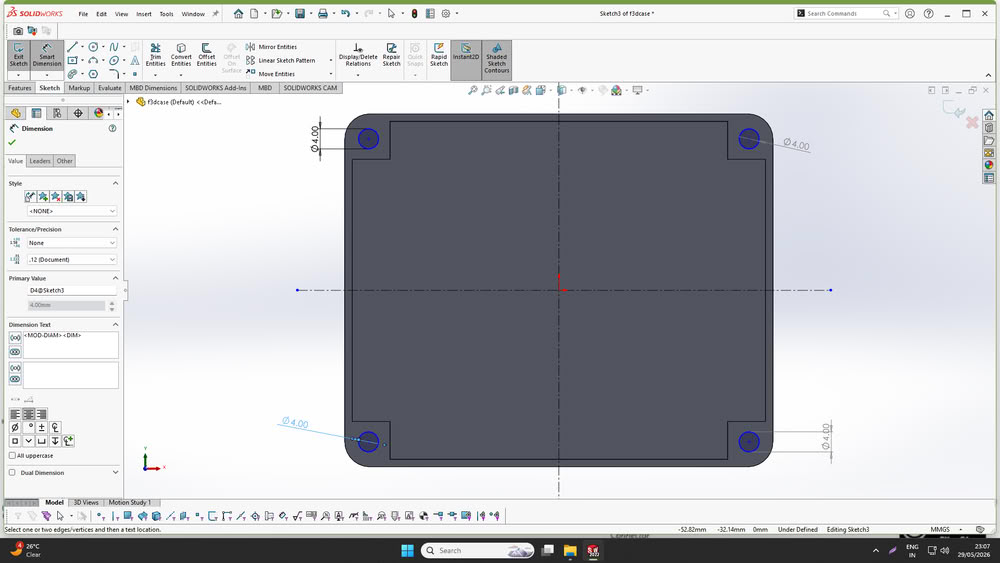
The casing was designed to accommodate all the system components safely and securely. Four corner holes were added to insert nuts and allow proper assembly of the enclosure.A dedicated hole was provided for installing a cable gland to ensure secure cable management.
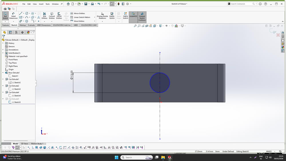
I also designed a slot for connecting the data cable to the XIAO ESP32C3 microcontroller without opening the enclosure.
Additionally, I designed a custom holder to mount the casing onto the motor used in the project.
After completing the design, all parts were fabricated using a 3D printer.
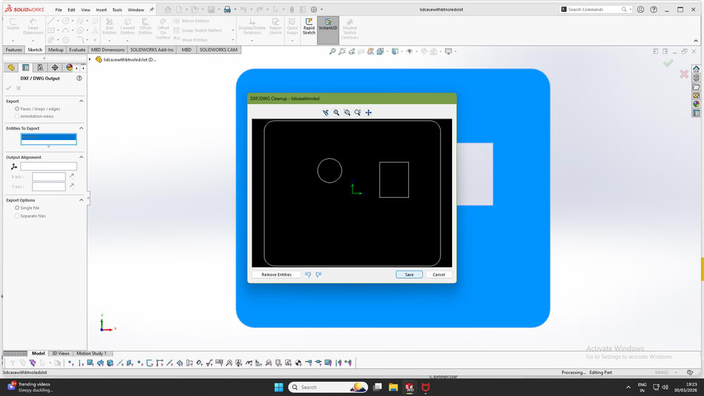
2D designing:-
After designing the casing, I designed a lid to cover the enclosure. The lid included a hole for mounting the push button and a rectangular slot for the OLED display, allowing the user to interact with the system and view the bead count easily.
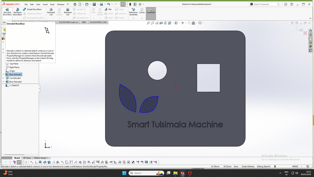
So, I export that file in DXF format.
Assembling 2D, 3D parts:-
I started the 2D and 3D assembly process by assembling all the fabricated parts.
First, I soldered the connections of the push button.
Then I placed OLED Display inside the slot and connect it properly.
After completing the soldering work, I connected all the electronic components and mounted the customized PCB and relay securely inside the casing box, as shown in the image.
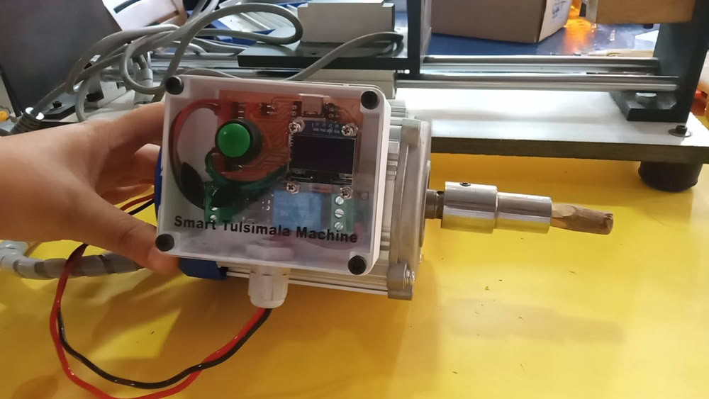
After completing the internal assembly, I attached the custom-designed holder to the casing box. The holder was then fitted into the slot on the motor, allowing the enclosure to be mounted securely on the machine. This completed the mechanical and electronic integration of the project.
Testing Hardware and relay logic:-
I tested the hardware by uploading the code and verifying whether the relay logic worked correctly. During the bead-making process, artisans turn on the motor to cut a Tulsi bead using a cutting tool. Once the bead is cut, they turn off the motor and collect the finished bead. Based on this workflow, I programmed the relay logic so that the bead count increases by one only when the motor is turned off after a cutting operation. This ensures that each completed bead is counted accurately and prevents false counts while the motor is running. The test results confirmed that the relay logic worked as intended.
Bead Cutting and counter:-
The video below demonstrates the Tulsi bead cutting process and the working of the bead counting machine.