Introduction
In this assignment, I explored the use of various output devices and learned how to interface them with the ESP32-C3 microcontroller. Output devices are components that allow a system to communicate its results to the outside world by producing signals we can see, hear, or feel. They are an essential part of electronics projects because they transform digital signals into practical actions or displays. During this work, I experimented with several output devices to understand their working principles and control methods. I used LEDs to indicate simple on/off states and to visualize basic signals. I also worked with the MAX7219 LED matrix display, which allowed me to display numbers, letters, and simple animations, helping me learn about multiplexing and matrix control. Additionally, I interfaced an OLED display to present text and graphics, which taught me how high-resolution displays can be controlled through communication protocols like I²C. I also included a servo motor SG90 in my experiments to understand how microcontrollers can control movement and positioning with precision. Through this assignment, I not only learned the technical connections and programming required to operate these devices but also gained hands-on experience in designing simple output-based projects, troubleshooting circuits, and observing how digital signals can drive physical actions. Overall, this work enhanced my understanding of electronics, microcontroller interfacing, and the practical applications of output devices in real-world projects.
 |
 |
Individual assignment
Task:Add an output device to a microcontroller board you've designed, and program it to do something.
Group assignment
Task:Measure the power consumption of an output device.
Link to view group assignmentGroup Assignment
Output Devices:
Output devices are parts of a computer or microcontroller system that take information from the system and show it to the outside world. They convert digital signals into something we can see, hear, or feel.
Output devices are essential components in electronics and computer systems that allow a system to communicate its results to the external environment. Unlike input devices, which send data or signals to a microcontroller or computer, output devices receive signals from the system and convert them into forms that humans or other machines can perceive or use. These devices can produce visual, auditory, or mechanical outputs, making them versatile tools in both simple and complex projects.
Output devices examples:
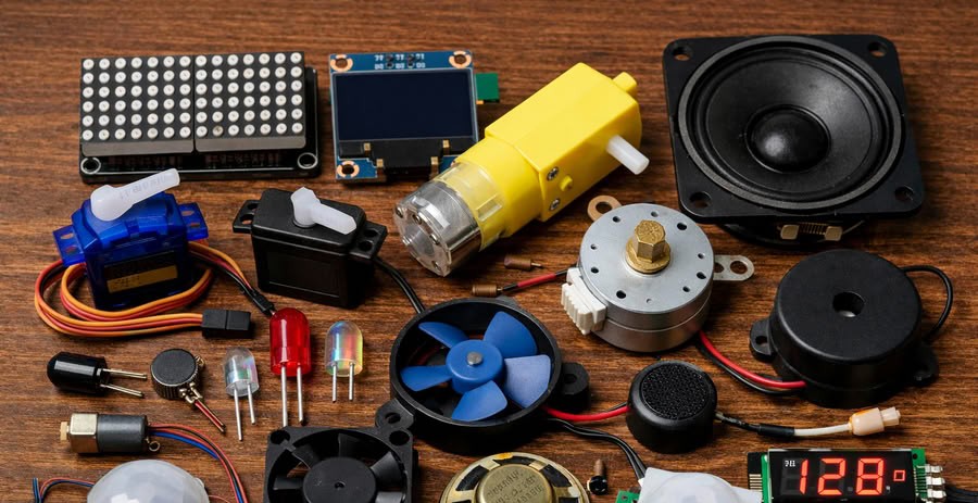
Image generated using chatgpt
Components I used for my board are as follows:-
1.LED
About LED
An LED, or Light Emitting Diode, is a semiconductor electronic component that produces light when an electric current passes through it. It is one of the most commonly used output devices in electronic circuits because it is simple to use, energy efficient, and has a long lifespan. When voltage is applied across the two terminals of an LED, electrons move through the semiconductor material and release energy in the form of light. LEDs are widely used in electronic projects to indicate power status, signal activity, or system conditions. They are available in different colors such as red, green, blue, and yellow, and each color is produced by different semiconductor materials. LEDs require a small amount of current to operate, which makes them suitable for microcontrollers like the ESP32, Arduino, and other embedded systems. To protect the LED from excessive current, a resistor is usually connected in series with it. Due to their low power consumption, compact size, and reliability, LEDs are commonly used in devices such as displays, indicators, lighting systems, and many electronic applications.
Types of LEDs
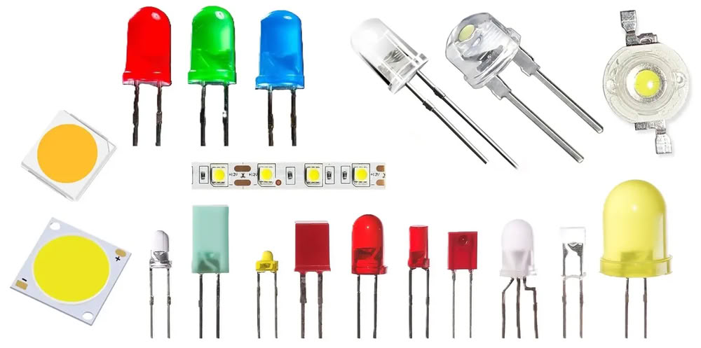
Image from hackatronic
- 1.Indicator LED:-Indicator LEDs are the most common type of LEDs used in electronic circuits. They are mainly used to show the status of a device, such as power on, power off, or signal activity. These LEDs are available in different colors like red, green, yellow, and blue and are widely used in microcontroller projects.
- 2.RGB LED:-RGB LEDs contain three LEDs inside a single package: red, green, and blue. By adjusting the brightness of these three colors, many different colors can be produced. RGB LEDs are commonly used in decorative lighting, displays, and creative electronics projects.
- 3.Infrared LED:-Infrared LEDs emit infrared light, which cannot be seen by the human eye. They are commonly used in remote controls, security systems, night vision devices, and communication systems.
- 4.SMD LED (Surface Mount Device LED):-SMD LEDs are very small LEDs that are mounted directly onto the surface of a printed circuit board. They are widely used in modern electronic devices such as televisions, mobile phones, LED panels, and digital displays.
- 5.High Power LED:-High power LEDs are designed to produce very bright light compared to normal LEDs. They are used in lighting systems such as LED lamps, flashlights, and street lighting. These LEDs often require proper heat management because they generate more heat.
diagram of LED

image from PCBTok
An LED has two terminals called the anode and the cathode. The longer lead of the LED represents the anode, which is the positive terminal, while the shorter lead represents the cathode, which is the negative terminal. For the LED to work properly, the anode must be connected to the positive side of the power supply and the cathode must be connected to the ground or negative side. This correct connection is called forward bias, and it allows current to flow through the LED so that it produces light.
Inside the LED, there are several important components. The outer transparent cover is called the epoxy lens, which protects the internal parts and helps focus the light. Inside the lens, there is a semiconductor die that forms the PN junction where light is produced. When electric current passes through this junction, electrons and holes combine and release energy in the form of light. The reflective cavity inside the LED helps direct the light outward to make it brighter. The anvil post and lead frame support the semiconductor chip and connect it to the external leads. There is also a flat spot on the LED body that helps identify the cathode side.
2.Servo motor (SG90):-
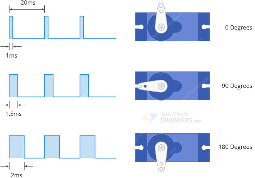
A servo motor SG90 is a small and lightweight actuator that is widely used in electronics, robotics, and microcontroller projects. It is designed to provide precise control of angular movement, which makes it very useful for applications that require accurate positioning. The SG90 servo motor can typically rotate between 0 degrees and 180 degrees and is commonly used with microcontrollers such as Arduino, ESP32, and other embedded systems. It operates using Pulse Width Modulation (PWM) signals, where the width of the pulse determines the position of the motor shaft. By changing the PWM signal from the microcontroller, the servo motor moves to the desired angle.
The SG90 servo motor usually has three connecting wires.The brown wire is connected to ground, the red wire is connected to the power supply (usually 5V), and the orange or yellow wire is used for the control signal from the microcontroller. Inside the servo motor, there are several components including a DC motor, a set of gears, a control circuit, and a position sensor. The gears reduce the speed of the motor and increase torque, while the position sensor continuously checks the angle of the motor shaft and sends feedback to the control circuit. This feedback system helps the servo motor maintain the correct position.

image from search engine
Motor structure
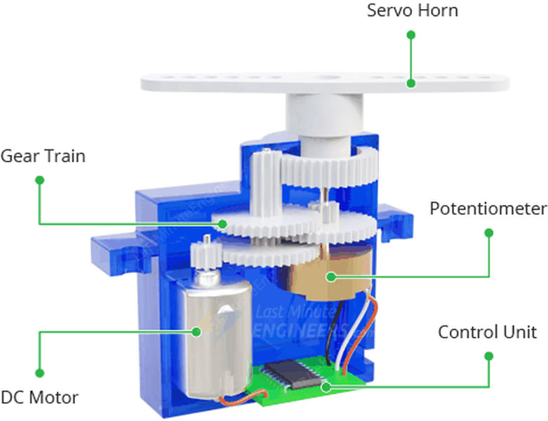
image from google
The SG90 servo motor has a compact internal structure that allows it to control the position of its shaft accurately. Inside the servo motor there are several important components that work together to produce controlled movement. The main parts include a small DC motor, a gear reduction system, a control circuit, and a position sensor called a potentiometer.
The DC motor is the main driving component inside the servo. When electrical signals are received from the microcontroller, the motor starts rotating. However, the DC motor rotates very fast and with low torque, so a gear reduction system is used. This gear system consists of multiple plastic gears that reduce the motor speed and increase the torque. The final gear is connected to the output shaft of the servo motor, which moves to the desired angle.
3.OLED display
An OLED display is a small electronic screen commonly used in microcontroller and embedded system projects to display text, numbers, and graphics. OLED stands for Organic Light Emitting Diode. Unlike traditional LCD displays, OLED displays do not require a separate backlight because each pixel produces its own light. This makes the display thinner, more energy efficient, and capable of showing high contrast images. OLED displays are widely used with microcontrollers such as Arduino, ESP32, and other development boards to show sensor data, messages, or system status.
Internal structure of the OLED
The internal structure of an OLED display consists of several thin layers placed between two electrodes. The most important layers include the organic semiconductor layer, the anode, and the cathode. When an electric current passes through these layers, the organic material emits light. Each pixel in the display contains tiny organic light-emitting diodes that glow when current flows through them. Because every pixel produces its own light, OLED displays can create very clear images with deep black colors.
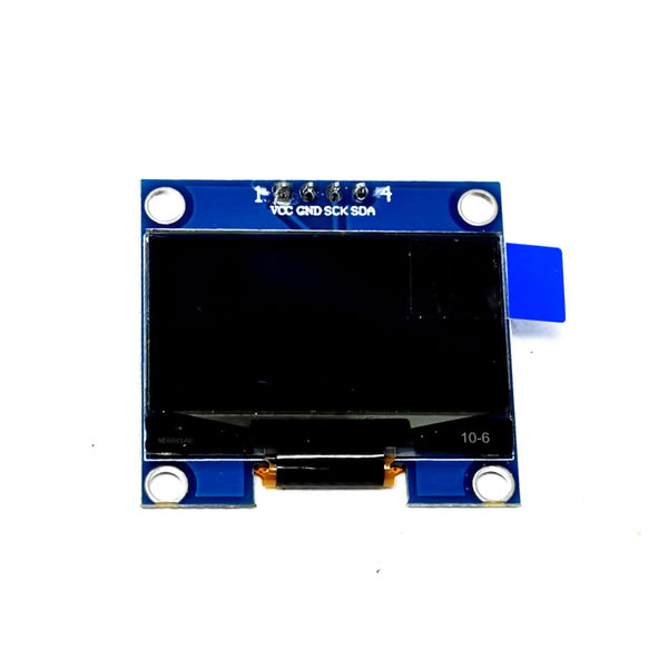
Most small OLED modules used in electronics projects have four main pins: VCC, GND, SDA, and SCL. VCC provides power to the display, GND is connected to ground, and SDA and SCL are used for communication through the I2C protocol. This communication method allows the microcontroller to send data and commands to the display easily. OLED displays are commonly used in electronic projects such as weather monitoring systems, digital clocks, IoT devices, and embedded systems where compact and clear visual output is required.
MAX7219 LED matrix
The MAX7219 is an integrated circuit that is commonly used to control LED displays such as 7-segment displays and LED dot matrix modules. It is designed to simplify the process of driving multiple LEDs by reducing the number of pins required from the microcontroller. Instead of controlling each LED individually, the MAX7219 uses a serial communication interface that allows a microcontroller to send data using only a few control lines. This makes it very useful in electronic projects where many LEDs need to be controlled efficiently.
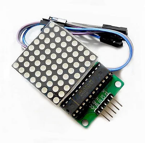
The VCC pin is used to supply power to the module and is usually connected to a 5V source. The GND pin is connected to the ground of the circuit and completes the electrical connection. The DIN pin, which stands for Data Input, is used to receive serial data from the microcontroller that controls the LEDs on the matrix. The CLK pin is the clock pin that helps synchronize the data transmission between the microcontroller and the MAX7219 driver. The CS pin, also called the Chip Select or Load pin, is used to tell the module when to accept and store the incoming data
Internal structure of the MAX7219 LED matrix
The serial data interface is responsible for receiving data from the microcontroller through the DIN, CLK, and CS pins. This interface converts the incoming serial data into parallel data that can be used to control the LEDs. The control logic manages the data flow and determines how the display should operate, such as turning LEDs on or off and adjusting brightness.The display register stores the data that determines which LEDs should be lit. The decoder can convert binary data into signals that control the LED segments when the chip is used with 7-segment displays. The MAX7219 also includes digit drivers and segment drivers. The digit drivers control the rows of the display, while the segment drivers control the columns. These drivers work together through a process called multiplexing, where rows and columns are activated very quickly to create the appearance that all LEDs are glowing continuously.
The chip also contains an internal current regulator that protects the LEDs and maintains consistent brightness. In addition, the intensity control circuit allows the brightness of the display to be adjusted through software. Because of this efficient internal structure, the MAX7219 can control up to 64 LEDs in an 8×8 matrix while requiring only a few control pins from the microcontroller.
Kicad software Schematic Diagram
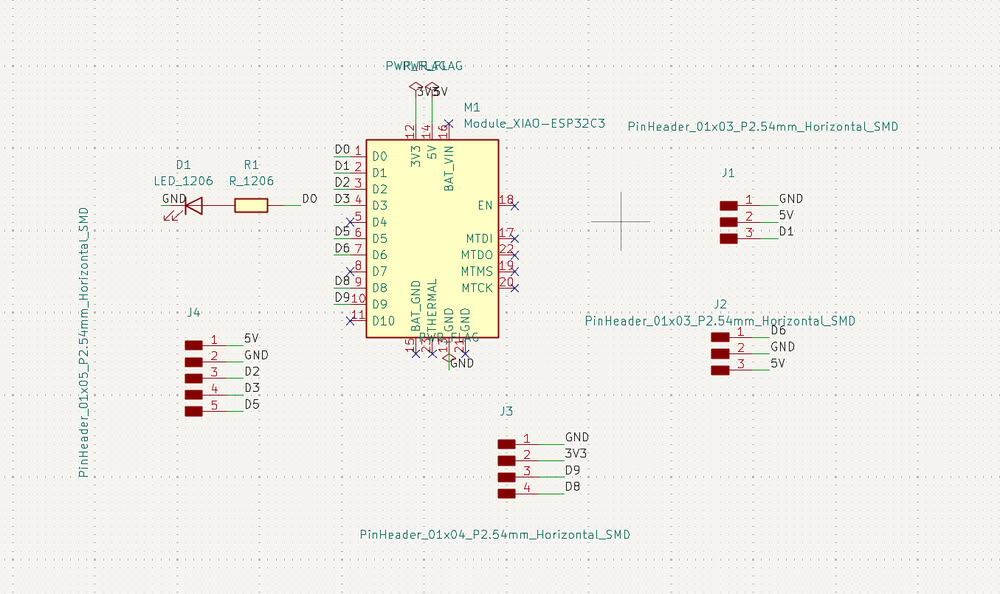
I have created the schematic diagram of my PCB. I placed the ESP32-C3 on the board and then added other components from the symbol libraries, such as a 3-pin header, a 4-pin SMD header, a 5-pin header, one LED, and one resistor. I also labeled the pins, like GND, VCC, D0, D1, as shown in the diagram.
Kicad software diagram in PCB editor
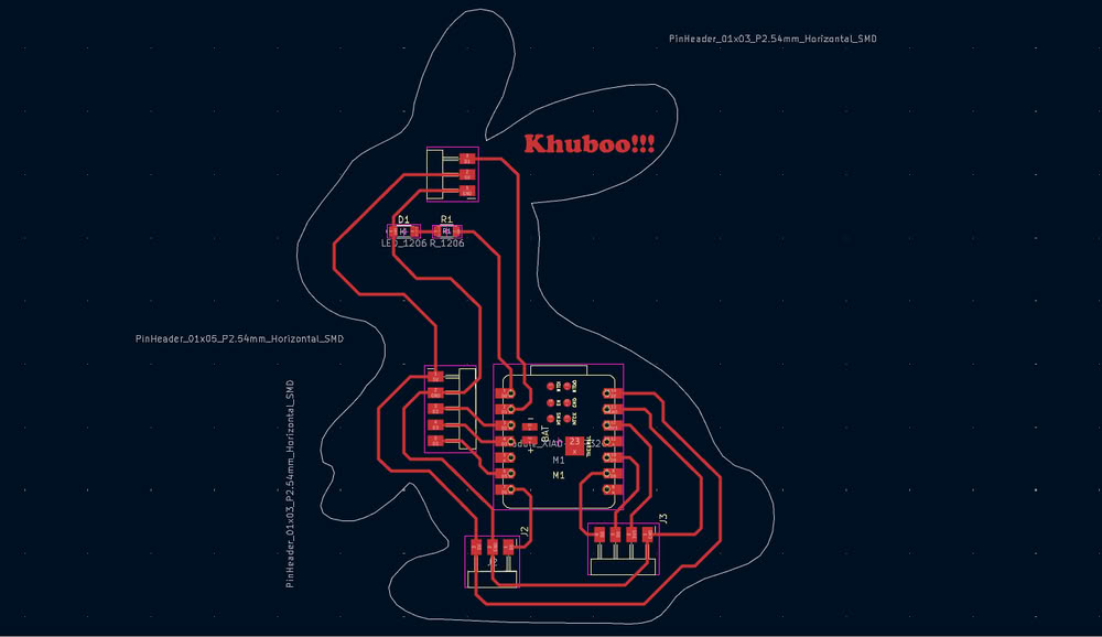
Then I go to PCB Editor where I route my PCB board.after this I plot gerber files to a specific folder for future use.
Link to view group assignmentGroup Assignment
Starting with gerber to image conversion
I used Gerber2Image to convert my Gerber files into PNG format. In this software, I simply drag and drop the Gerber files, and the program automatically loads and converts them into image files.
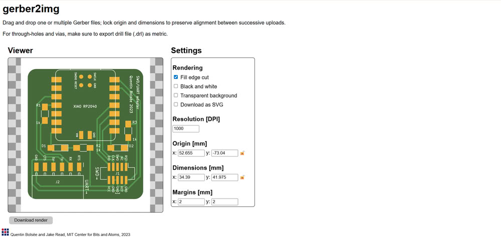
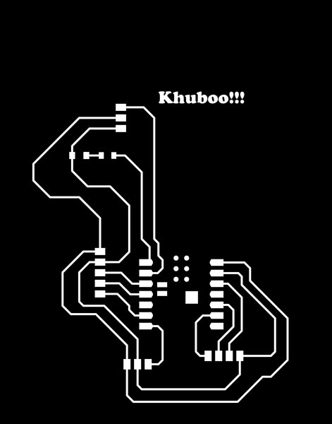
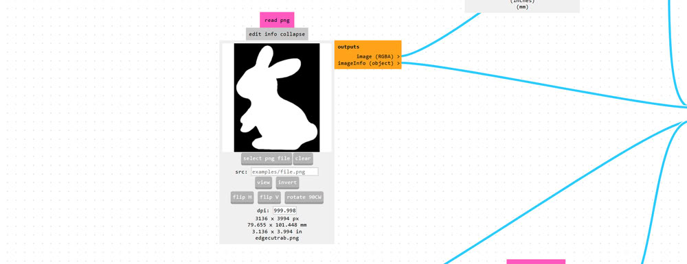
I used Gerber2Image to convert my PCB Gerber file into a PNG image. First, I selected the F.Cu (Front Copper) file and dragged and dropped it into the software. After loading the file, I chose the black and white rendering option to clearly show the PCB traces. Then, I saved the rendered output as a PNG file, which can be used for PCB milling.
After that, I selected the Edge.Cuts file, which defines the outline of the PCB board, and similarly rendered and saved it as a PNG image.

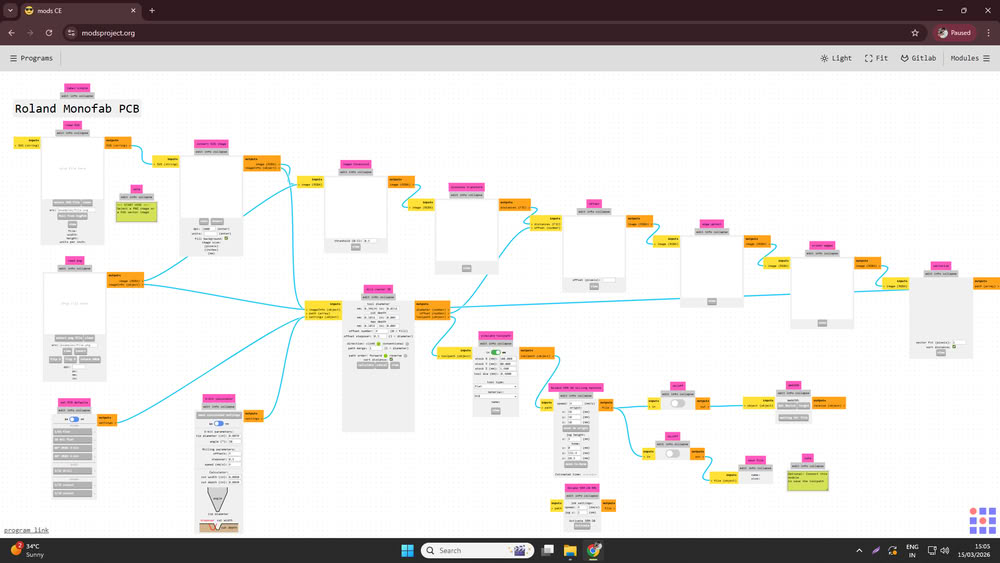
Using mods for G-code generation
I opened mods ce then click on programs and select machine I am using for pcb making.
I used Mods CE to convert the PNG files into G-code for PCB milling.
First, I opened Mods CE and clicked on Select PNG file, then I uploaded the trace cut PNG file.
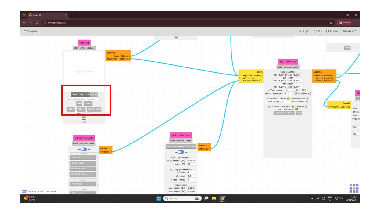
Since I was using a 1/64 milling bit for cutting the PCB traces, I selected the 1/64 tool option.
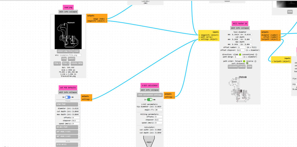
After that, I set the cutting speed to 4 mm/s and set the origin coordinates X = 0, Y = 0, Z = 0. Then I configured the settings by disabling the top button and enabling the bottom one to prepare the file for saving.
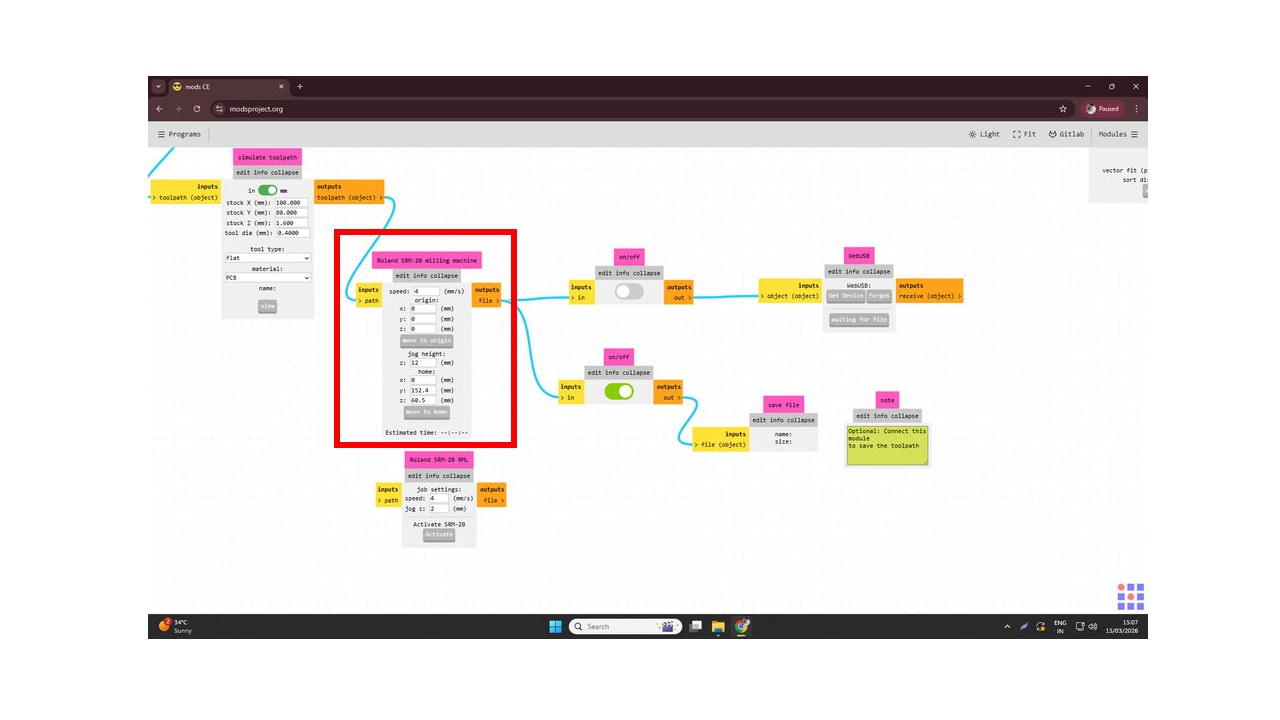
Similarly, I uploaded the Edge.Cuts PNG file into Mods CE to generate the toolpath for cutting the PCB outline. After selecting the PNG file, I chose the 1/32 cutout tool option since a 1/32 milling bit is used for cutting the board edges.
Then I set the speed to 4 mm/s and defined the origin coordinates as X = 0, Y = 0, Z = 0. After that, I configured the settings by turning off the top button and enabling the bottom one to prepare the file for saving. Finally, I clicked on Calculate, which generated the toolpath and saved the .rml file.
Using V-Panel for tracing and cutting process:-
I set proper tool for tracecut(1/64 inch end mill) during milling process.
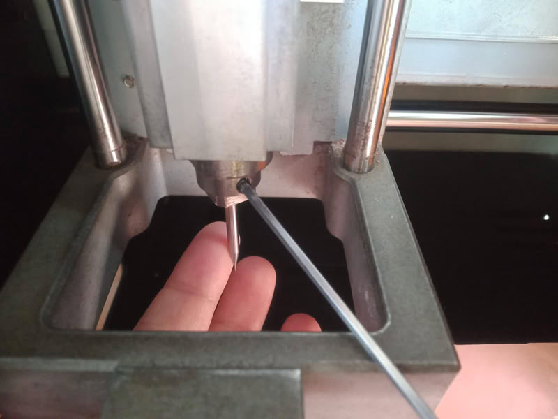
Then I set x,y origin to 0.
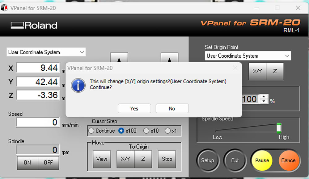
Also I set z axis to 0 by putting 1/64 inch end mill bit at proper position.
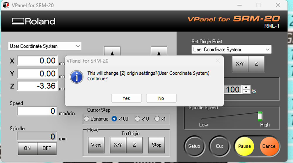
I set z origin to 0.
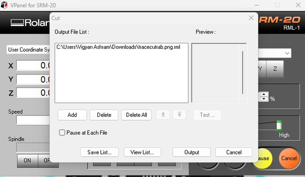
Then I click on cut option and select add to add tracecut file for tracing process.
After completing process I use vaccum cleaner to clean the part.
After this I change the bit to 1/32 inch end mill and put edgecut file for cutting purpose.

I add edgecut for for edge cutting purpose.
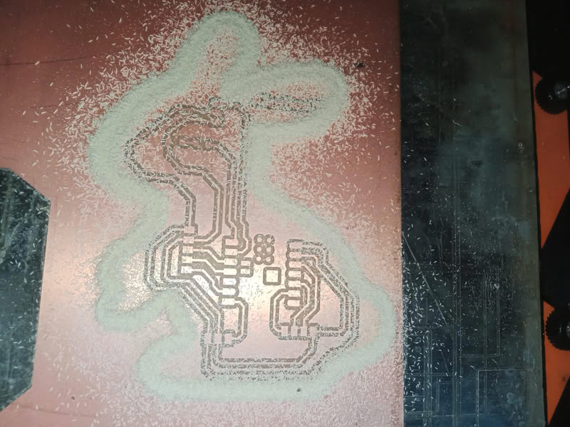
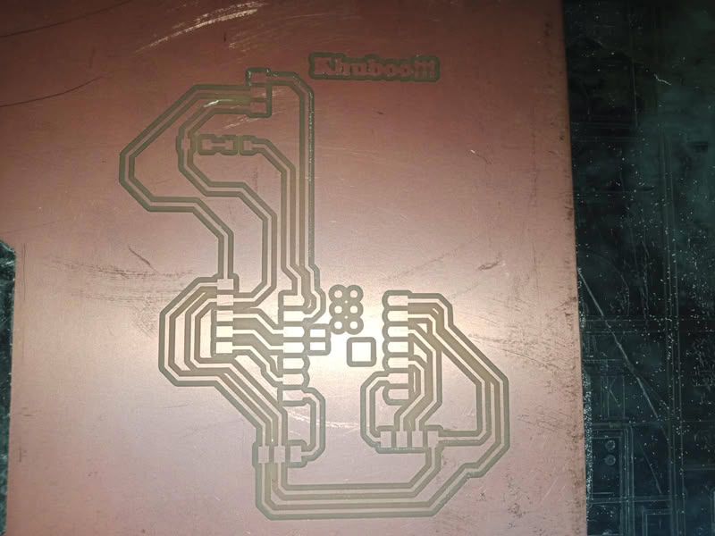
milling process get completed here.
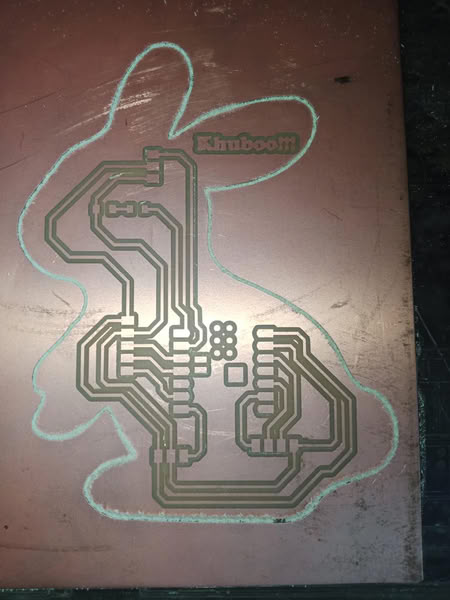
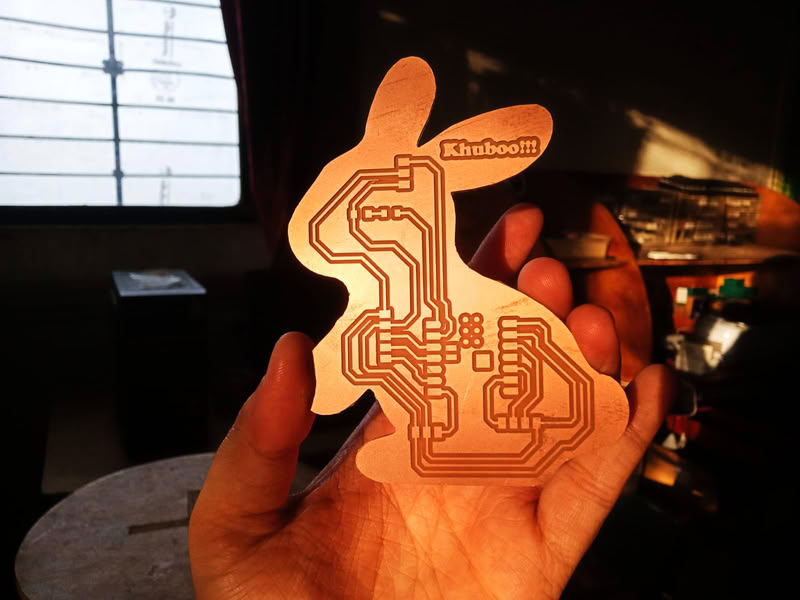
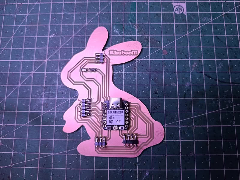
And here is my milled board
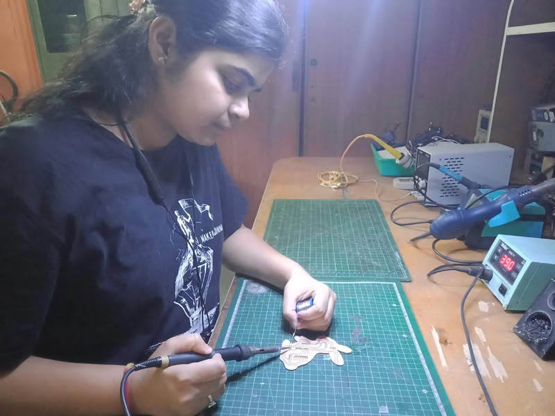
Soldering Process:-
The soldering process is used to attach electronic components to the PCB after the board is milled. First, the milled PCB is cleaned properly to remove dust or copper particles. Then all the required components such as resistors, LEDs, microcontroller, and connectors are placed on their respective pads according to the schematic design. A soldering iron is heated and solder wire is applied to the joint where the component lead and copper pad meet. The heat melts the solder, allowing it to flow around the component lead and pad, creating a strong electrical and mechanical connection. This process is repeated for all components on the board. After soldering, the board is visually inspected to ensure there are no loose connections, excess solder, or short circuits between the pads.
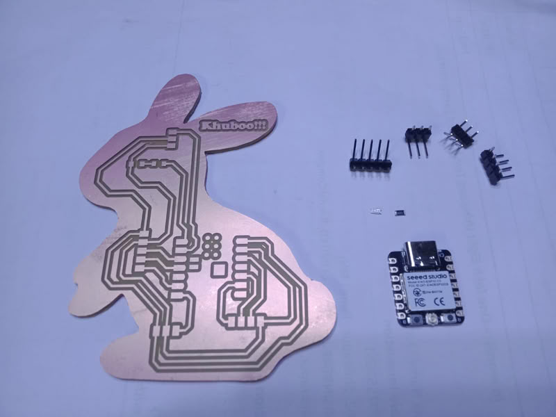
Components used are as follows:-
- 1.XIAO ESP32-C3 microcontroller
- 2. one 4-pin connectors
- 3. one 5-pin connectors
- 4. two 3-pin connectors
- 5. one LED
- 5. one Resistor
 |
 |
 |
 |
Uploading code:-
1.OLED Display
Pin description
- VCC:-VCC is the power supply pin of the OLED display. It is connected to the power source of the microcontroller. Most OLED modules work with 3.3V or 5V power depending on the module type.
- GND:- stands for ground. This pin is connected to the ground of the microcontroller to complete the electrical circuit.
- SDA:-SDA stands for Serial Data line. It is used to transfer data between the microcontroller and the OLED display through the I2C communication protocol. The microcontroller sends display information such as text or graphics through this pin.
- SCK:-SCL stands for Serial Clock line. It provides the clock signal for I2C communication. This clock signal synchronizes the data transfer between the microcontroller and the OLED display.
LED pin connections:-
VCC → 3.3V,GND → GND, SDA → GPIO8, SCK → GPIO9
Here is the code for OLED display
#include <Wire.h>
#include <Adafruit_GFX.h>
#include <Adafruit_SSD1306.h>

#define SCREEN_WIDTH 128
#define SCREEN_HEIGHT 64

Adafruit_SSD1306 display(128, 64, &Wire, -1);

void setup() {

  Wire.begin(8,9);   // SDA, SCK pin I connect

  display.begin(SSD1306_SWITCHCAPVCC, 0x3C);
  display.clearDisplay();

  display.setTextSize(2);
  display.setTextColor(WHITE);

  display.setCursor(20,25);
  display.println("My Day!!!");

  display.display();
}

void loop() {
}
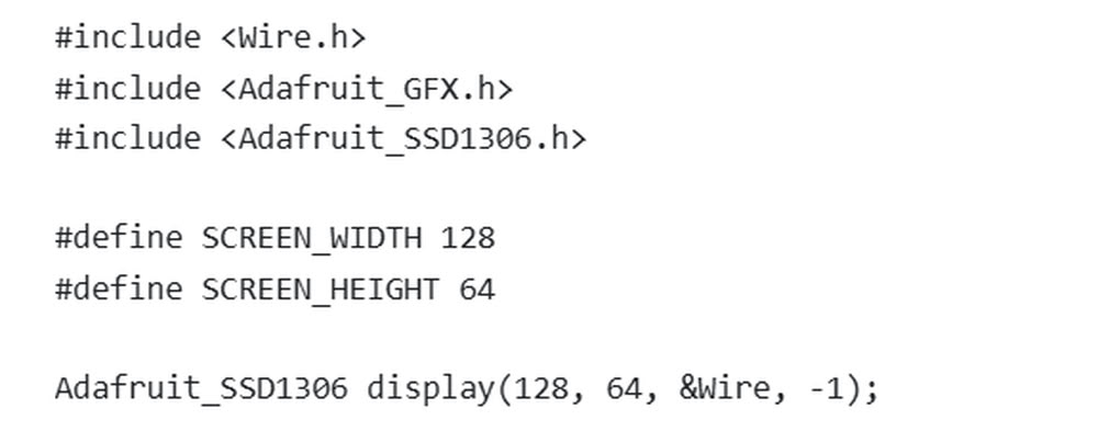
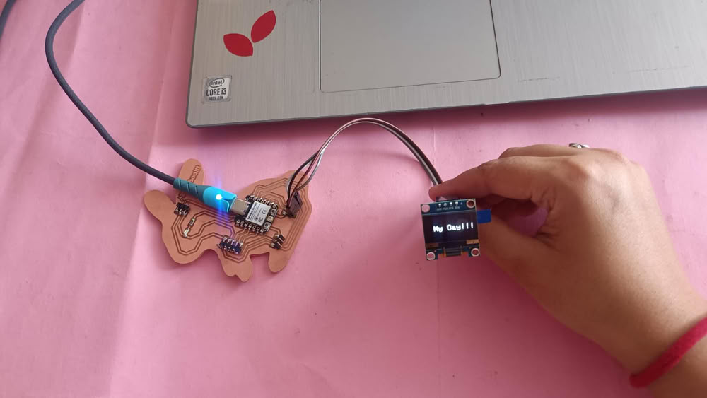
This code is used to display text on an OLED screen using an ESP32. First, the libraries Wire.h, Adafruit_GFX.h, and Adafruit_SSD1306.h are included so the ESP32 can communicate with the OLED display and show graphics or text. Then, SCREEN_WIDTH and SCREEN_HEIGHT define the display size as 128×64 pixels. The line Adafruit_SSD1306 display(128, 64, &Wire, -1); creates an OLED display object for communication through I2C.
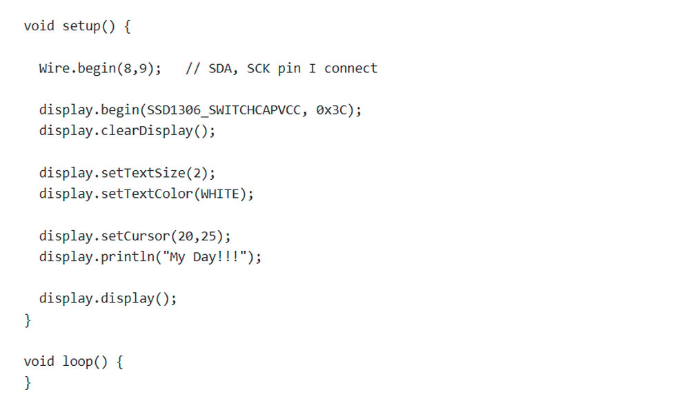
Inside the setup() function, Wire.begin(8,9); starts I2C communication using GPIO8 as SDA and GPIO9 as SCL. The line display.begin(SSD1306_SWITCHCAPVCC, 0x3C); initializes the OLED display with address 0x3C. Then, display.clearDisplay(); clears the screen before showing anything. display.setTextSize(2); sets the text size, and display.setTextColor(WHITE); sets the text color to white. After that, display.setCursor(20,25); sets the position of the text on the screen, and display.println("My Day!!!"); prints the message on the OLED display. Finally, display.display(); updates the screen to show the text. The loop() function is empty because the message only needs to be displayed once.
For writing the above code I took help from chatgpt.
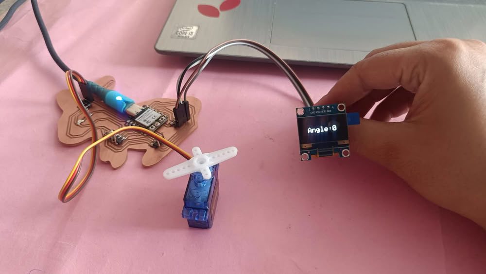
2.OLED with servo motor(SG90)
I tried to move servo motor at different angles and show it on oled display. so first I connect servo motor with the board and then I also connect oled display and upload code to see it's workiing process.
Pin description
servo motor
- The VCC pin is the power supply pin of the servo motor. It is usually connected to a 5V power source. This pin provides the necessary voltage required for the motor to operate.
- The GND pin is connected to the ground of the power supply or microcontroller. It completes the electrical circuit and allows the servo motor to function properly.
- The signal pin is used to control the movement of the servo motor. It receives Pulse Width Modulation (PWM) signals from the microcontroller such as ESP32 or Arduino. Based on the PWM signal, the servo motor rotates to a specific angle between 0 degrees and 180 degrees.
servo and OLED pin connections:-
OLED Display
VCC → 3.3V,GND → GND, SDA → GPIO8, SCK → GPIO9
Servo motor SG90
VCC → 5V,GND → GND, Signal → D1
Here is the code I took with the help of chatgpt
#include <Wire.h>
#include <Adafruit_GFX.h>
#include <Adafruit_SSD1306.h>
#include <ESP32Servo.h>

#define SCREEN_WIDTH 128
#define SCREEN_HEIGHT 64

Adafruit_SSD1306 display(128,64,&Wire,-1);
Servo myServo;

void setup() {

  Wire.begin(8,9);                 // SDA, SCL for OLED
  display.begin(SSD1306_SWITCHCAPVCC, 0x3C);

  myServo.attach(3);               // Servo on D1 (GPIO3)
}


void showAngle(int angle)
{
  display.clearDisplay();
  display.setTextSize(2);
  display.setTextColor(WHITE);
  display.setCursor(20,25);
  display.print("Angle:");
  display.println(angle);
  display.display();
}

void loop() {

  myServo.write(0);
  showAngle(0);
  delay(2000);

  myServo.write(90);
  showAngle(90);
  delay(2000);

  myServo.write(180);
  showAngle(180);
  delay(2000);

}
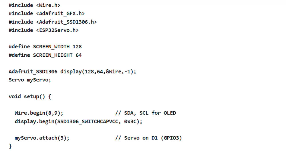
This code is used to control a servo motor and display its angle on an OLED screen using an ESP32. First, the required libraries for OLED display and servo motor control are included. Then, SCREEN_WIDTH and SCREEN_HEIGHT define the OLED display size as 128×64 pixels. The line Adafruit_SSD1306 display(128,64,&Wire,-1); creates the OLED display object, and Servo myServo; creates a servo motor object. Inside the setup() function, Wire.begin(8,9); starts I2C communication using GPIO8 as SDA and GPIO9 as SCL for the OLED display. The line display.begin(SSD1306_SWITCHCAPVCC, 0x3C); initializes the OLED screen, and myServo.attach(3); connects the servo motor to GPIO3.
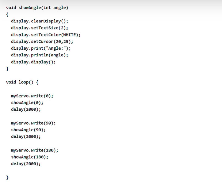
The showAngle(int angle) function is used to display the servo angle on the OLED screen. It first clears the display, sets text size and color, then prints the text “Angle:” along with the current angle value. In the loop() function, the servo motor moves to three different positions: 0°, 90°, and 180° using myServo.write(). After each movement, the showAngle() function displays the angle on the OLED screen. A delay(2000); gives a 2-second pause before moving to the next position. This program helps demonstrate servo motor movement along with real-time angle display on the OLED screen.
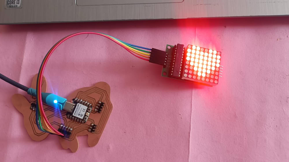
3.MAX7219 LED matrix
Next I took MAX7219 LED matrix to display something . I tried this first time.
Pin description
- VCC is the power supply pin of the MAX7219 module. It is connected to the 5V power source of the microcontroller or development board. This pin provides the voltage required for the LED matrix and the MAX7219 driver chip to operate.
- GND is the ground pin. It is connected to the ground of the microcontroller. This pin completes the electrical circuit and ensures proper operation of the module.
- DIN stands for Data Input. This pin receives serial data from the microcontroller. The data sent through this pin controls which LEDs will turn on or off in the matrix display
- The CS pin is used to select the MAX7219 chip when sending data. It tells the module when the incoming data should be accepted and stored. This pin helps the microcontroller control the timing of data transfer.
- CLK provides clock pulses that allow the MAX7219 to read the incoming data from the DIN pin correctly.
Here is the code
#include <MD_MAX72xx.h>
#include <SPI.h>
#define HARDWARE_TYPE MD_MAX72XX::FC16_HW
#define MAX_DEVICES 1

#define DATA_PIN 4
#define CLK_PIN 7
#define CS_PIN 5

MD_MAX72XX mx = MD_MAX72XX(HARDWARE_TYPE, DATA_PIN, CLK_PIN, CS_PIN, MAX_DEVICES);

byte heart[8] = {        // array part
B01100110,
B11111111,
B11111111,
B11111111,
B01111110,
B00111100,
B00011000,
B00000000
};

byte arrow[8] = {
B00011000,
B00011100,
B11111111,
B11111111,
B00011100,
B00011000,
B00010000,
B00000000
};

byte smile[8] = {
B00111100,
B01000010,
B10100101,
B10000001,
B10100101,
B10011001,
B01000010,
B00111100
};


void drawSymbol(byte symbol[])
{
  for(int i=0;i<8;i++)
  {
    mx.setRow(0,i,symbol[i]);
  }
}

void setup() {
  mx.begin();
  mx.clear();
}

void loop() {

  drawSymbol(heart);
  delay(2000);

  drawSymbol(arrow);
  delay(2000);

  drawSymbol(smile);
  delay(2000);

}
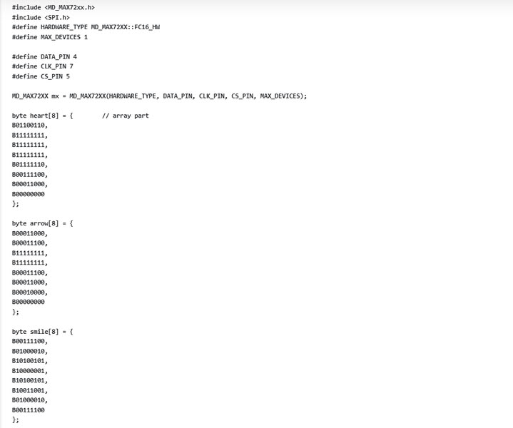
This code is used to display different symbols on an 8×8 LED matrix using the MAX7219 display module and ESP32. First, the libraries MD_MAX72xx.h and SPI.h are included for controlling the LED matrix through SPI communication. Then, HARDWARE_TYPE and MAX_DEVICES define the type and number of LED matrix modules used. The pins DATA_PIN, CLK_PIN, and CS_PIN are assigned for communication between the ESP32 and the matrix display. The line MD_MAX72XX mx = MD_MAX72XX(...); creates the display object. After that, three arrays named heart, arrow, and smile are created. These arrays store binary patterns that represent different symbols on the LED matrix.

The function drawSymbol(byte symbol[]) is used to display a symbol on the LED matrix. A for loop sends each row of the selected symbol pattern to the display using mx.setRow(). Inside the setup() function, mx.begin(); starts the LED matrix display and mx.clear(); clears any previous data. In the loop() function, the program displays the heart symbol first, waits for 2 seconds, then shows the arrow symbol, and finally the smile symbol. Each symbol is displayed one after another with a delay using delay(2000);. This program creates a simple animation effect by changing symbols on the LED matrix display.
In this code, arrays are used to store the patterns of symbols that will be displayed on the MAX7219 LED Matrix Module. An array like heart[8] contains eight binary numbers, where each number represents one row of the 8×8 LED matrix. In these binary values, 1 means the LED is ON and 0 means the LED is OFF. The program reads these values and sends them to the matrix row by row, which creates the shape of the symbol such as a heart, arrow, or smiley face on the display.
The above code I took from chatgpt
Problem I faced:-
During the output devices assignment, I faced a problem while using the MAX7219 LED matrix with the ESP32. Initially, the display was not showing correct symbols or sometimes nothing appeared on the screen. The main issue was incorrect wiring of the DATA, CLK, and CS pins, and also wrong pin selection in the code. After checking the connections and matching them properly with the code, the display still did not work properly because the brightness and module type settings were not correct. and ensured proper power supply to the module. After these changes, the MAX7219 LED matrix started displaying symbols correctly.
Code files
Click here to download original files
PNG and .rml files
Click here to download original files