System Integration Week
Overview
Group Assignment
Not Listed for this weekIndividual Assignment
Design and document the system integration for your final projectResearch and Inspiration
Will FillIntegrating The Systems of My Final Project
What this Project Is
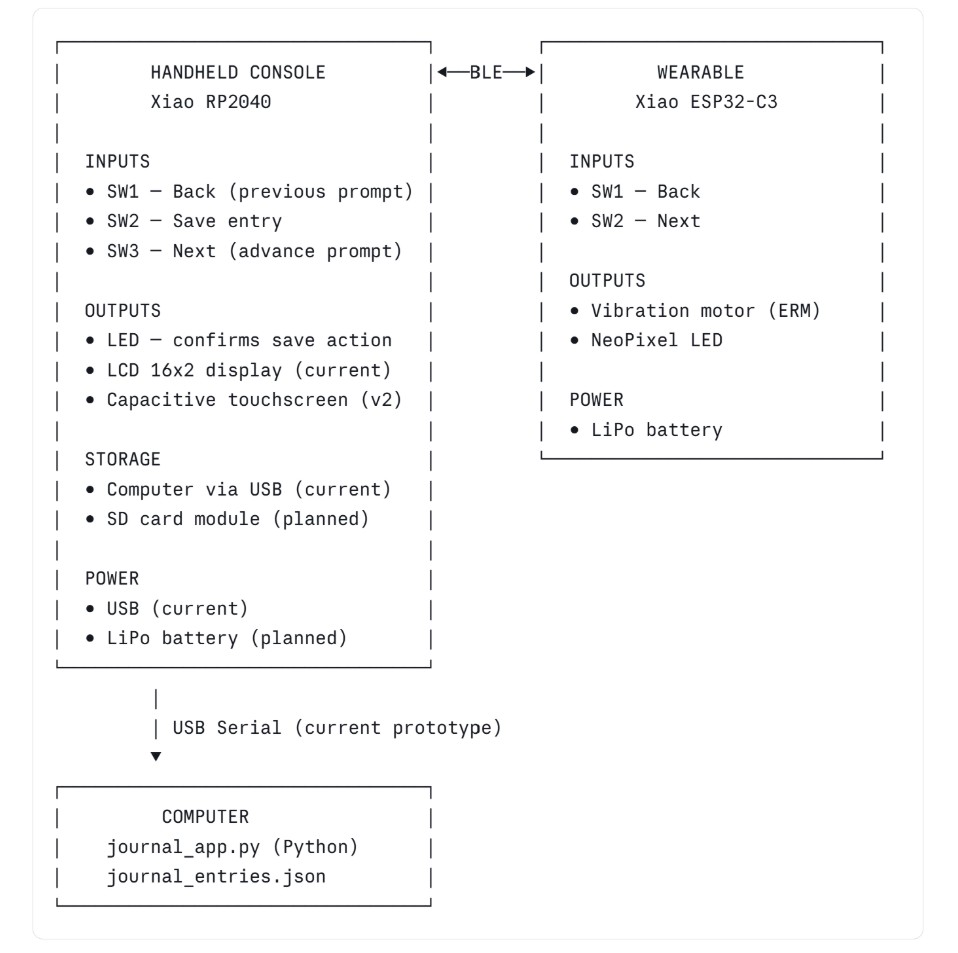
This project is a two-device system designed to guide users through structured entrepreneurship and innovation journaling prompts. There are two parts. A handheld console displays prompts and stores responses. A wrist-worn wearable delivers physical sensations timed to the journaling session — vibration and light — to interrupt habitual thought patterns and encourage new cognitive associations. The design is grounded in CBT-informed interaction principles: the body is prompted to feel something at the moment the mind is asked to think differently. The two devices work together as one experience. The console is where thought is captured. The wearable is where the body is engaged. Neither is complete without the other.System Architecture
How The Two Systems Relate
Signal Flow: What Triggers What
| User Action | Console Response | Wearable Response |
| Session starts | Displays Prompt 1 | Vibration Pulse - "Begin" Cue |
| User presses Next (console or wearable) | Advances to Next Prompt | Vibration Pulse - "transition" cue |
| User Presses Save | Saves entry, LED flashes | NeoPixel Flash - "committed" cue |
| User Presses Back | Returns o Previous Prompt | Short Vibration - "reverse" cue |
| Session Complete (all 7 prompts) | Shows Summary Screen | Long Vibration + Neo Pixel Pattern |
Note: The signal trigger logic above represents the intended design. As of this week, the application layer (journal_app.py) is functional on the computer. Hardware triggering and BLE communication are planned for the next build stage.
Prototype Stages
| Stage | Console | Wearable | Communication | Storage | Status |
| Stage 1 (Current) | Python app on computer | Not Yet Built | USB Serial | JSON file on computer | WORKING |
| Stage 2 (Next) | CircuitPython + LCD on console PCB | Vibration + Neo Pixel Swatch | Wired Test Connection | SD Card on Console | This Week Testing |
| Stage 3 | Console Fully Standalone | Wearabke PCB fabricated | BLE Bidirectional | SD Card | Planned |
| Stage 4 - Final | Capacitive Touchscreen Console | Wearable Integrated into Wrist Cuff Garment | BLE Directional | SD Card | Planned |
The core experience: prompts, responses, progression, is the same at every stage. What changes is the hardware it runs on and the components that deepen the interaction, making it more interpersonal.
Device 1: Handheld Console
Physical Housing
The console housing was designed in Fusion 360 and test printed in PLA using FDM. The form factor is handheld and has been sized to sit comfortably in one hand with buttons accessible by thumb.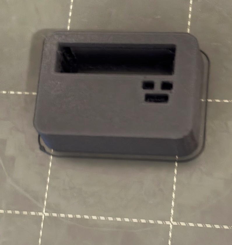
Packaging Plan for Final Version
- PCB mounted inside housing on standoffs
- Buttons seated through apertures in the top face of the housing
- LCD display visible through a recessed window in the face
- USB port accessible through a cutout in the housing side (current) → replaced by internal LiPo + charge port in final version
- All wires routed internally with no exposed connections
PCB Schematic
The console PCB was designed in KiCad. It uses the Xiao RP2040 (pre-soldered) as the microcontroller, three tactile push buttons for navigation, one LED for feedback, and a 4-pin I2C header for the display.
Components
| Ref | Component | Value | Purpose |
| U1 | XIAO RP2040 - SMD | - | Main Controller |
| SW1 | Tactile Push Button | - | Back - Previous Prompt |
| SW2 | Tactile Push Button | - | Save - Commit Entry |
| SW3 | Tactile Push Button | - | Next - Advance Prompt |
| R1 | Resistor | 10k Ohm | Pull Up for SW1 |
| R2 | Resistor | 10k Ohm | Pull Up for SW2 |
| R3 | Resistor | 10k Ohm | Pull Up for SW3 |
| R4 | Resistor | 1k Ohm | Current Limiter for LED |
| D1 | LED | - | Confirms save action |
| J1 | Conn_01x04 | 4-pin Header | 12C Display connection (VBUS, GND, SDA/D4. SCL/D5) |
Pin Assignments:
| Xiao Pin | Conected To |
| D0 (P26_A0) | SW1 (Back button) junction |
| D1 (P27_A1) | SW2 (Save button) junction |
| D2 (P28_A2) | SW3 (Next button) junction |
| D3 (P29_A3) | R4 → LED → GND |
| D4 / SDA | J1 Pin 3 (display data) |
| D5 / SCL | J1 Pin 4 (display clock) |
| VBUS | J1 Pin 1 (display power) |
| GND | J1 Pin 2, button legs, LED cathode |
| 3V3 | Pull-up resistor legs (R1/R2/R3) |
Pull-up Resistor wiring (corrected during design):
During schematic design I initially wired the pull-up resistors incorrectly (I connected them between GND and the button, with 3V3 on the far side of the button). This would have left the GPIO pins floating when buttons were not pressed, causing phantom inputs. The correct configuration is:
Device 2: Wearable
Concept
The wearable is a wrist cuff worn during a journaling session. It delivers two types of physical output: vibration and light. The physcial outputs are timed to events triggered by the console. The intent is somatic pattern interruption: using unexpected physical sensation to break the brain out of its habitual thinking patterns at the exact moment a new prompt asks it to think differently.
Vibration is the primary output because it cannot be intellectually filtered out the way a visual cue can. The sensation arrives before the user can anticipate it. NeoPixel light adds a visual layer, the color can carry meaning (transition, save, completion) without requiring the user to look at the console.
Pysical Form
- Placement: Wrist
- Form factor: Fabric cuff with embedded PCB and components
- Soft-hard connection strategy: [To fill in after a future Saturday session — snap connectors / conductive thread / embedded header]
- Textile base: [To fill in — fabric type and construction method]
PCB Schematic: Wearable (planned)
PCB Design and Fabrication
The wearable PCB was designed as a second iteration of the electronics design week work, after the console PCB was completed. Because this addition happened after electronics design week was originally submitted, I returned to that week's documentation to record the full process there.
Link to Electronics Design Week, Wearable Addition (coming soon)
The following is a summary of the wearable PCB scope for system integration reference.
Microcontroller: Xiao ESP32-C3 — chosen for its built-in BLE 5.0, which the console's RP2040 does not have. Both chips share the same Xiao footprint, so the fabrication approach is consistent across both PCBs.
Components:
| Ref | Component | Value | Purpose |
| U1 | XIAO ESP32 - C3 | - | Microcontroller + BLE 5.0 |
| SW1 | Tactile Push Button | - | Back - Previous Prompt |
| SW2 | Tactile Push Button | - | Next - Advance Prompt |
| R1 | Resistor | 10k Ohm | Pull Up for SW1 |
| R3 | Resistor | 100 Ohm | Transistor Baser Resistor |
| R2 | Resistor | 10k Ohm | Pull Up for SW2 |
| M1 | ERM Vibration Motor | - | Primary Somatic Output |
| Q1 | NPN Transistor | 2N2222 | Motor Driver |
| D1 | Flyback Diode | 1N4148 | Protects transistor from motor back - EMF |
| LED1 | NeoPixel | WS2812B | Visual Sensation Output |
| J1 | Battery Connector | - | LiPo power |
Pin assignments:
| ESP32-C3 PIN | Connected To |
| GPIO2 | SW1 (Back button) junction |
| GPIO3 | SW2 (Next button) junction |
| GPIO4 | Transistor base → vibration motor |
| GPIO5 | NeoPixel data |
| Bat | LiPo Connector Positive |
| GND | LiPo connector negative, button legs, motor ground |
Fabrication Notes: (will be updated as I go)
- Copper tape traces on acrylic
- Soft-hard connection method: (to fill in after Saturday session)
- Testing and continuity check results: (to fill in)
Reflections
What System Integration Means for My Final Project
System integration for this project means ensuring that two separate physical devices, a software application, a firmware layer, and a storage system all work together as a single coherent experience. None of these components is the project on its own. The project is what happens when a user sits down, picks up the console, feels the wearable on their wrist, reads a prompt, and writes something they haven't thought of before. Every hardware and software decision either supports or undermines that moment.
What this week forced me to think through
Designing the system integration documentation forced me to be honest about the gap between what I have planned and what I have actually built and tested. The software application works. The KiCad schematic is drawn. Everything else is still ahead of me. Laying out the prototype stages made it clear that the path from here to a standalone console with a BLE-connected wearable is longer than it might feel when working on individual pieces in isolation.
It also forced me to define the trigger logic for the wearable (not just that it will vibrate, but when it vibrates and why, and what each sensation is meant to communicate to the user). That specificity is what makes this a designed experience rather than a collection of components.
What is still unresolved
The wearable's physical construction is still being developed. For example, how the PCB attaches to a fabric cuff, what the cuff is made from, and how components are seated and protected during wear. These parts are the most open design question remaining. The wearable electronics are planned but not yet started. BLE communication between the two devices is the most technically complex piece of the system and has not yet been prototyped. These are the next walls to climb.
Notes Received During Wednesday Review for This Week
This week I asked a few questions about my final project during the weekly review wednesday session. One of the notes I received was that due to the precarious battery connectivity of the RP 2040 I should cosnider switching my board to the RP 2350. A few people in the chat said that utilizing the RP 2350 solved any battery issues and works really well, so I will be searching for the RP 2350 on amazon and moving forward with that board instead of the RP 2040. Adrian (Torres, global open time lead) let me know in the chat that they have the same footprints and should not need to change my schematics rather just switch the board.
From Vimeo
Sound Waves from George Gally (Radarboy) on Vimeo.
From Youtube