Week 15
Interfaces and Applications Programming
Overview
This week's assignment required writing an application for an embedded board that I designed and made, that interfaces a user with an input and/or output device. My work this week is directly connected to my final project: a wearable and handheld console system that guides users through design iteration using prompts. For this week I focused on the computer-facing side of that system — building the application layer that will eventually run on the handheld console. The interface demonstrates how a user moves through prompts, types long-form responses, saves their entries, and reviews past writing. Communication between the application and my DIY PCB is handled over USB serial: a physical button on the board advances the user to the next prompt, and an LED confirms the save action.
Group Assignment
Group assignment: Compare as many tool options as possible. Document your work on the group work page and reflect on your individual page what you learned.Individual Assignment
Individual assignment: Write an application for the embedded board that you made. that interfaces a user with an input and/or output device(s)Research
What is Interface and Application Programming?
Interface and application programming bridges the gap between embedded hardware and the humans who use it. Embedded programming focuses on what the microcontroller does internally and interface programming focuses on how a person interacts with that system. Most interface programing is accomplished through screens, buttons, keyboards, sliders, or any other input/output mechanisms. For this week I explored several approaches to building a user interface that communicates with a microcontroller:
Tool Comparisson (Group Assignment as a remote student)
[Link to group assignment page here. Summarize in 2-3 sentences what tools ]
My personal takeaway from the group work was: [I found that Python with tkinter offered the fastest path from idea to working prototype for someone new to GUI programming, while web-based approaches using the Web Serial API were more visually flexible but required more setup. For my final project, Python made the most sense.
My final project is a dual-device system: a handheld console and a wearable that work together to guide users through entrepreneurial and innovation-focused design journaling. The system uses CBT-informed prompts to encourage the user to examine assumptions, reframe problems, and build new cognitive habits through reflective writing.
This week's work that connects to my final project:
Computer runs the journal app USB serial communicates with PCB Button on PCB advances prompts Entries saved to local .json file LED confirms save action Computer screen shows UI
The core logic: prompts, user input, data storage, state management; is identical between this prototype and my final product. The hardware layer is what changes.
Interface/App 1
Objective
Hardware
| Component | Quantity | Purpose |
| Seeed Studio Xiao RP2040 | 1 | Microcontroller |
| Tactile Push Button | 1 | Input (advances to next prompt) |
| LED | 1 | Output (Confirms Save Action) |
Why These Components
The component choices are intentionally minimal for this week's prototype. The button was chosen as the input because it maps directly to the final product interaction for the "next" that exists outside the screen. The LED was chosen as the output because it provides immediate confirmation feedback, which is a core UX principle for the journaling flow: the user needs to know their entry was saved before moving on. The 100Ω resistor limits current through the LED to a safe level. Without it, the LED would draw too much current from the Xiao's GPIO pin and could damage the board over time.
Testing the Fabrixiao
Before building the PCB, I tested my existing Fabrixiao to determine whether it was still functional since i've been iterating with this same board since FAB 25 and Fabricademy. 1. Connected the Fabrixiao to my computer via USB-C 2. Opened Device Manager on Windows (right-click Start → Device Manager) 3. Looked under Ports (COM & LPT) for a new COM port
Software Steps
PCB Design - KiCad Schematic
My PCB for this week implements the minimum viable circuit to satisfy the Fab Academy requirement: one input device (button) and one output device (LED), connected to a microcontroller I designed and made myself (the Fabrixiao, which carries the Xiao RP2040). The schematic was drawn in KiCad 10.0
Schematic Walkthrough
The circuit consists of four components:
- U1 — Fabrixiao (Xiao RP2040) The microcontroller. It receives power via USB-C and communicates with the computer over USB serial. Pin D0 is configured as a digital input (with internal pull-up) for the button. Pin D1 is configured as a digital output for the LED.
- SW1 — Tactile push button One leg connects to pin D0 on the Xiao. The other leg connects to GND. When pressed, D0 is pulled LOW, which the firmware detects as a button press event. The internal pull-up resistor on the Xiao keeps the pin HIGH when the button is not pressed, preventing false triggers.
- R1 — 100Ω resistor In series with the LED. Limits current to a safe level for the Xiao's GPIO pin (max 12mA per pin on the RP2040). With a 3.3V output and a ~2V LED forward voltage, the current through the circuit is approximately (3.3 - 2.0) / 100 = 13mA — within safe limits.
- LED1 — LED Anode connects to the resistor (which connects to D1). Cathode connects to GND. Lights up when D1 is pulled HIGH by the firmware, confirming a save action to the user.
Schematic Process
wiring etc.
Hardware Steps
Physical PCB Fabrication
I documented how I fabricaed my PCB using acrylic and copper tape in weeks 6 and 8.
Firmware
Platform Choice: Circuit Python
I chose CircuitPython for the FabriXiao firmware for three reasons:
1. No compilation step. CircuitPython runs code directly from a code.py file on the board's USB drive, which means I can edit and test without an IDE or build process — critical for a rapid prototype timeline.
2. Native USB serial. The usb_cdc module makes serial communication with the computer straightforward and requires no additional libraries on either end.
3.Strong library ecosystem. When I add a display and SD card in the next prototype phase, CircuitPython has mature, well-documented libraries for both (adafruit_displayio_ssd1306, adafruit_sdcard).
Firmware Code
The firmware runs a continuous loop that monitors the button state. When a press is detected (pin pulled LOW), it flashes the LED once to confirm, then sends the string NEXT\n over USB serial to the computer application.
Key Implementation Notes
1. The button uses an internal pull-up resistor (Pull.UP), so unpressed = True, pressed = False
2. Debouncing is handled by only triggering on the falling edge (transition from True to False), not on the held state
3. The LED flash duration (0.1s) is intentionally short — just long enough to be perceived, not long enough to delay the next press
4. usb_cdc.data is the secondary serial channel used for data communication, separate from the REPL console
Building the Application
Platform Choice: Python with Tkinter
I chose Python with the Tkinter GUI lirary for the destop application because:
1. tkinter is built into Python so there is no additional install required beyond Python itself which is a time saver for me.
2. pyserial provides straightforward serial port access with minimal boilerplate.
3. Threading in Python allows the serial listener to run in the background without freezing the UI.
4. The application is intended to eventually be replaced by firmware running on the console itself, so a simple, readable codebase matters more than visual sophistication at this stage.
Installation
1. Downloaded Python 3.12.x from python.org
2. During installation: checked "Add Python to PATH"
3. Enabled long path support when prompted (typed y, rebooted)
4. Opened Command Prompt and ran: pip install pyserial
5. Verified with: python 3.12.x version and pip show pyserial
Application Architecture
The application has four functional layers
1. Prompt Layer
2. Storage Layer
3. UI Layer
4. Serial Communication Layer
The Prompts
The seven prompts guide uses through an entrprenurial design iterations session:
1. The Problem You're Obsessed With
2. Your Unfair Advantage
3. Assumptions You're Making
4. The Person You're Designing For
5. What Failure Would Teach You
6. The Simplest Possible Version
7. Iteration Reflection
Application Code
Running the Application
1. Save journal_app.py to a folder on your computer
2. Open Command Prompt in that folder (Shift + right-click → Open PowerShell/Command Prompt here)
3. Run: python journal_app.py
4. The application opens. If the board is connected, the status dot turns green within a few seconds.
5. If the board is not connected, the app still runs fully (it retries the connection every 3 seconds in the background.)
During testing of the prototype without the board hooked up I was able to prove that the code is functional and the app behaves
as it is inteded to.
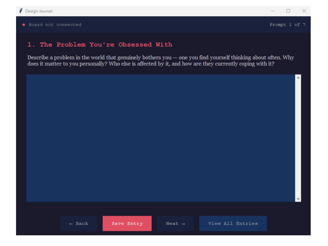
I was able to answer prompt 1.
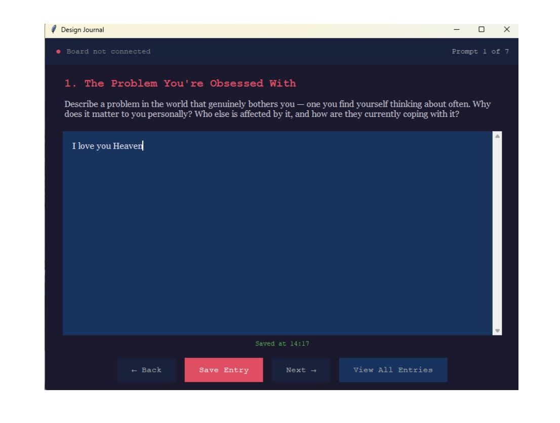
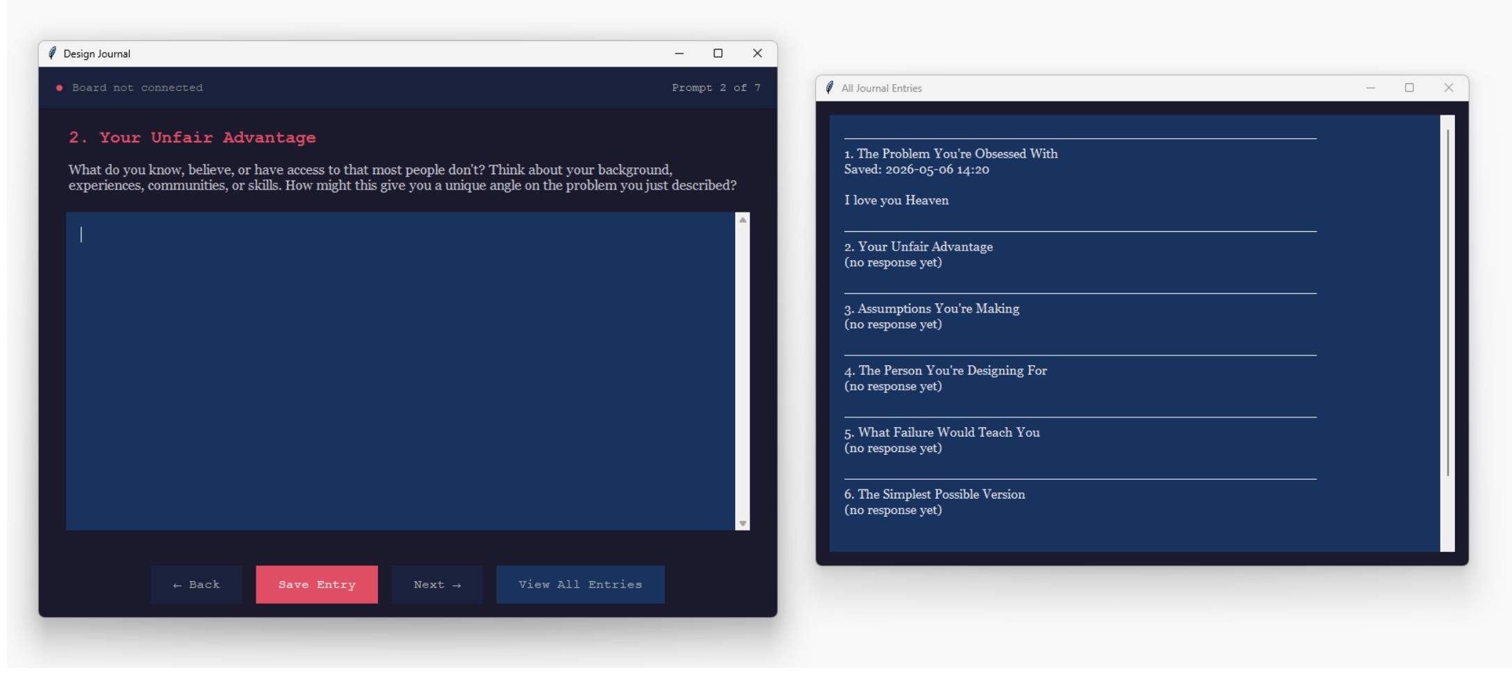
Navigating to the second prompt also noting that the first entry was time stamped at the bottom of the screen.
Viewing all entries.
System Communication
How the Board and Application Talk
The board and application communicate over USB serial at 115200 baud. This uses the Xiao RP2040's built-in USB hardware. The communication protocol for this prototype is intentionally simple:
The board speaks to the computer and sends the message NEXT\n which means that the button was pressed and the user can advance to the next prompt
In the next prototype phase, bidirectional communication will be added so the application can also send data to the board. For example, sending the current prompt number to display on the OLED screen.
Serial Port Detection
The application scans available COM ports and connects automatically to the first port whose description contains "CircuitPython" or "USB Serial." This means no manual port configuration is needed. Once the board is plugged in, the app finds it.
Problems Encountered
Problem 1.
What I tried:
Result:
Results
Technical References
CircuitPython documentation: https://docs.circuitpython.org Seeed Studio Xiao RP2040 wiki: https://wiki.seeedstudio.com/XIAO-RP2040/ Python tkinter documentation: https://docs.python.org/3/library/tkinter.html pyserial documentation: https://pyserial.readthedocs.io
Reflection
What I learned this week:
What I would do differently:
Demo Videos
From Vimeo
Sound Waves from George Gally (Radarboy) on Vimeo.
From Youtube