Week 14
Molding and Casting
Overview:
This week I explored materials for creating moulds and casts. I will also explore desiging my own mold and test various materials to create casts.Understanding Moulding and Casting
Molding (Moulding) and casting is a fabrication method used to reproduce the shape of an object. Molding refers to creating a hollow within a material that captures the geometry and outer details of the original. Casting is the process of introducing a liquid material into that form, allowing it to solidify, and then removing it from the molded material to produce a duplicate. This approach is widely applied in manufacturing, prototyping, and artistic production due to its precision and versatility.
Whether manufacturing components for business or producing detailed prototypes and replicas, it enables accurate and repeatable duplication of objects. For this week of Fab Academy, I focused on the core concepts behind the process, including preparing a model digitally, designing an effective mold, and producing a finished cast that captures the original design goals.
A few things are really important in this process. Avoiding undercuts is one of the most important, in my opinion. Undercuts are features that prevent the object from being removed cleanly from the mold, often leading to damage to the mold during demolding. Proper geometry ensures the model can be extracted without resistance. Undercut geometries tend to lock the part in place causing a LOT of resistance. Another consideration to keep in mind is draft angles. Draft angles are small tapers applied to vertical surfaces which provied successful mold releases. Draft angles reduce friction and allow the model or the final cast once casted to cleanly be removed.
Once the model design is completed with undercuts and draft angles considered, the mold fabrication can begin using subtracive or additive processes. One subtractive process is CNC milling and one additive process is 3d printing. With CNC milling, the design that will be filled with liquid is removed from a material, like wax. With 3D printing, the mold's entire shape is printed out using a 3d printer and filament, leaving open areas where liquid will be poured.
Assignment: Group Assignment 1. Review the safety data sheets for each of your molding and casting materials 2. Make and compare test casts with each of them 3. Compare printing vs milling molds
Individual Assignment 1. Design a mold around the process you will be using. 2. Produce it with a smooth surface finish that does not show the production process toolpath. 3. Use it to cast parts.
Group Assignment
Steps 1. Step 1 2. Step 2
Molding Materials
To create my first mold I will be using Smooth On
Casting Materials
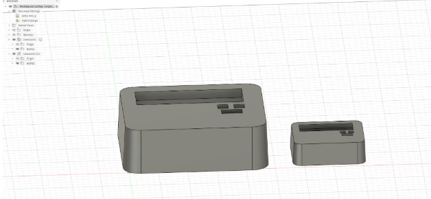
I will be casting using a 3D printed copy of my final project created using Fusion 360
Mold Desining & Milling: Fusion 360 & Roland - Will explore if tine permits
Steps 1. Step 1 2. Step 2
Mold Desining & 3d Printing: Fusion 360 & Prusa 3d Printing
Steps
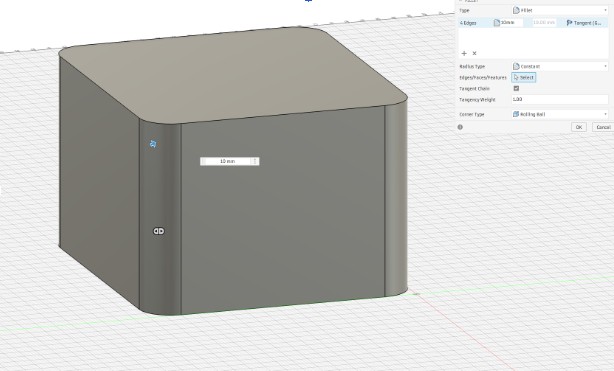
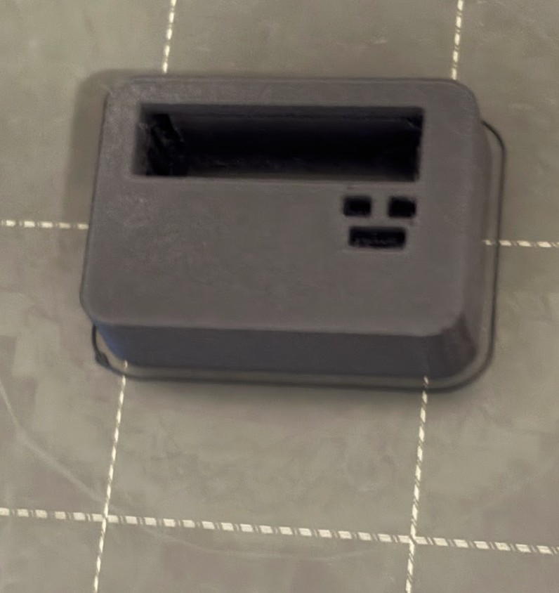
Step 1: Create the Main Box * Sketch: Create a new sketch on the Top Plane. * Rectangle: Draw a Center Rectangle from the origin: 95mm x 85mm * Extrude: Press E and extrude it upward by 60mm. * Fillet: Press F. Select the four vertical corner edges and give them a 10mm radius to make it handheld-friendly.
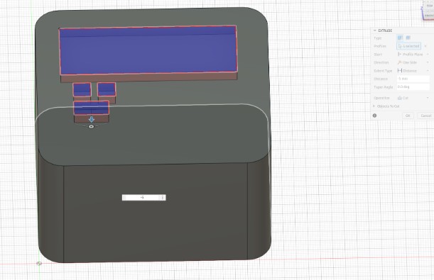
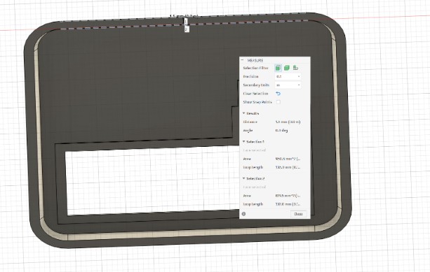
Step 2: The LCD and Button Cutouts - Sketch on Top Face: Select the top surface of your block and create a new sketch. - LCD Window: Draw a Center Rectangle near the top half: 72mm x 25mm (this is the visible area of a 1602 LCD). - Button Holes: Draw two circles (diameter 7mm) below the LCD window where you want your "Advance" buttons to sit. - Extrude Cut: Press E, select the rectangle and circles, and extrude downward by -5mm (this creates the indentations for your cast).
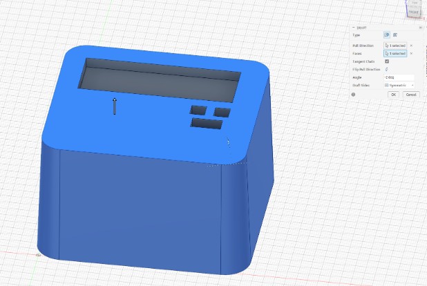
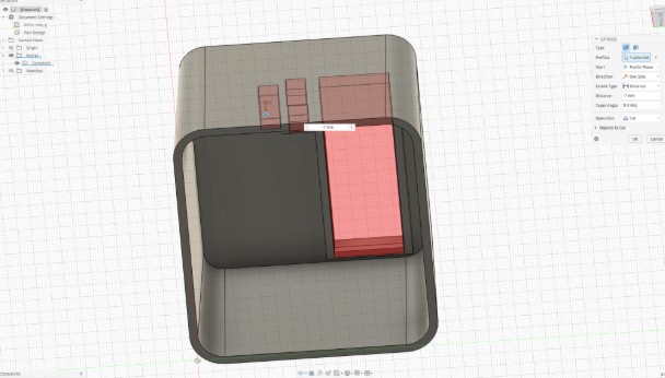
Step 3: Add the Draft Angle (CRITICAL for Molding) - Go to Modify > Draft. - Pull Direction: Select the Top Face. - Faces: Select the four side faces of your box. - Angle: Set to -2 degrees. You should see the bottom of the box get slightly wider than the top. - Change the Draft Sides to Symmetric - Click OK
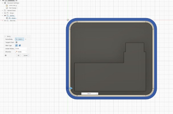
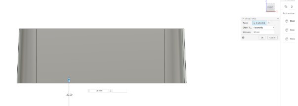
Step 4: Create the Interior Cavity (The "Void") - Shell Command: Go to Modify > Shell. - Select the BOTTOM face of the block. - Inside Thickness: Set to 3mm. This hollows out the inside so your electronics have a home.
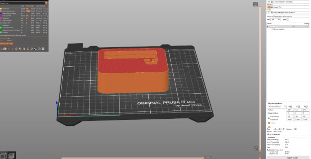
Step 5: Export for Printing * In the Browser on the left, right-click your Component or Body. * Select Save as Mesh (or Export > STL). * Set Refinement to High. * Open in your slicer (Cura/PrusaSlicer) and start the print!
Step 6: PRUSA Slicing The time frame if 6 hours 56 minutes is a bit long. I explored options.
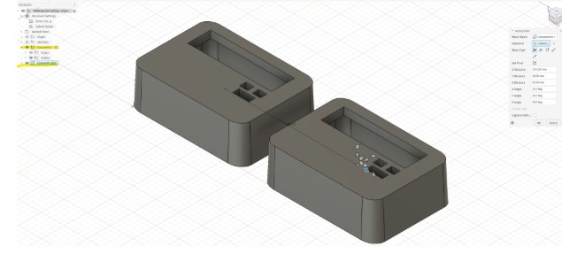
Step 7: How to Half-Scale the Model * I had to change the Design type from part design to hybrid design in order to create a separate copy. * Steps for Paste New * Right-click the body in the browser tree and select "Create Components from Bodies". * Right-click component from the browser tree. * Select "Copy". * Deselect components by clicking outside the browser tree in the workspace of Fusion. * Right-click the workspace of Fusion. * Select "Paste New". * The Move arrows will come up, move the second component away from the original
Moulding
Steps
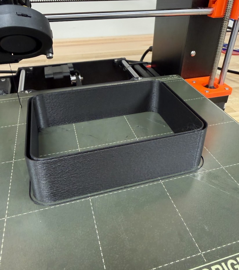
Creating the Mold was a pretty interesting process for me. I needed to focus on the amount of time I would have in order to set my 3d print in the mold and allow time for setting. I realized my 3d print was going to take too long at it's "final project" size. My initial attempt to print the "final project" size was a fail.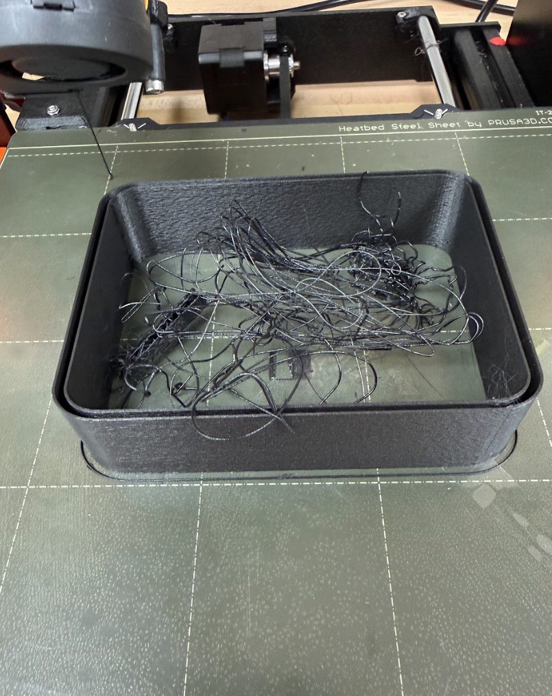
Casting
Steps
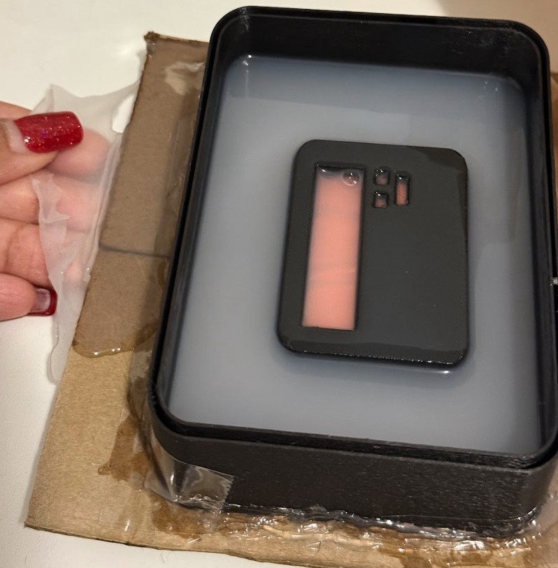
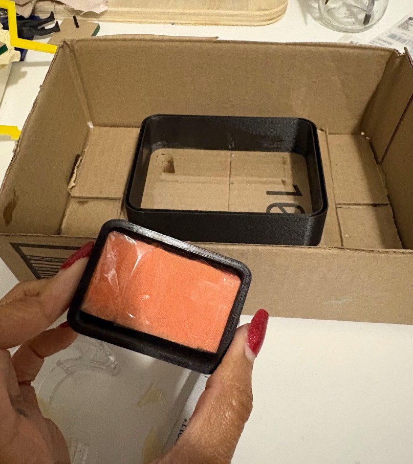
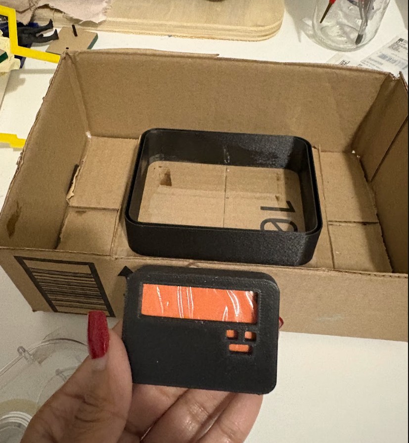
It was finally time for me to start mixing my smooth on and pouring the silicone around my 3d print. I was really excited to get this poured as the setting time would be overnight and I'd be waking to a huge success or a beautiful disaster. I am wearing gloves for safety. In the background you can see how I repurposed the "failed 3D Print" and where the half scale 3d print is positioned within it in relation to the carboard box.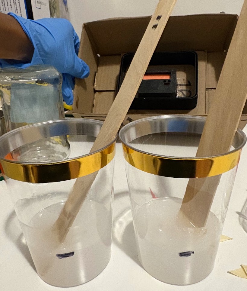
Final Results
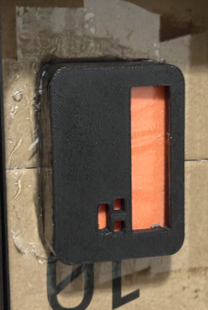
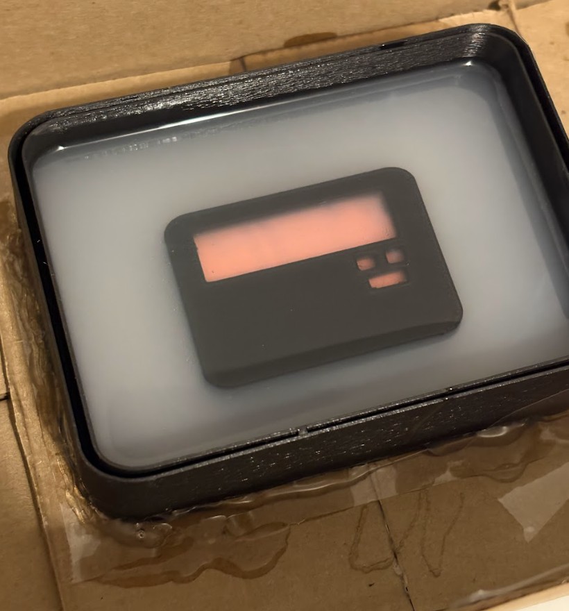
Results of Smooth On Silicone over 3d Printed Half Scale Mold
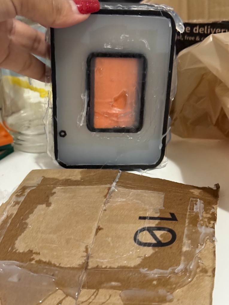
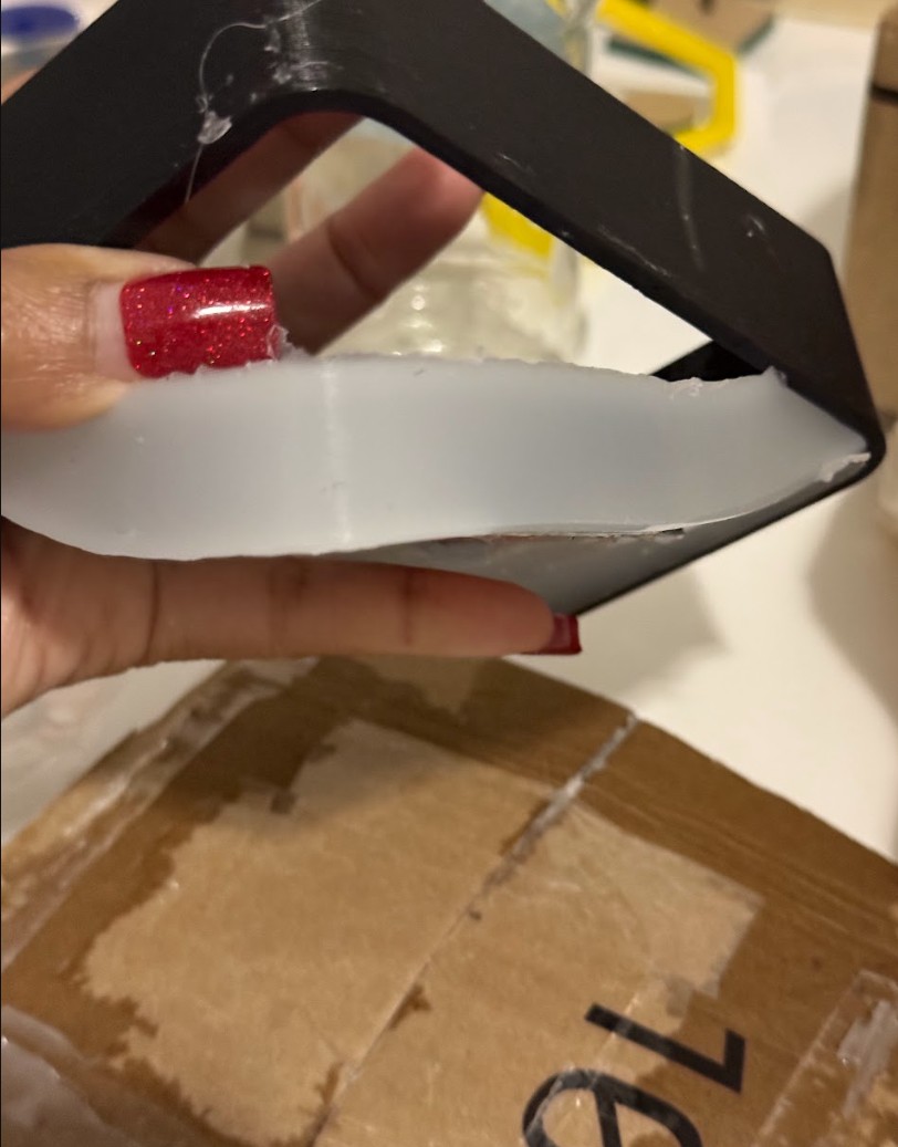
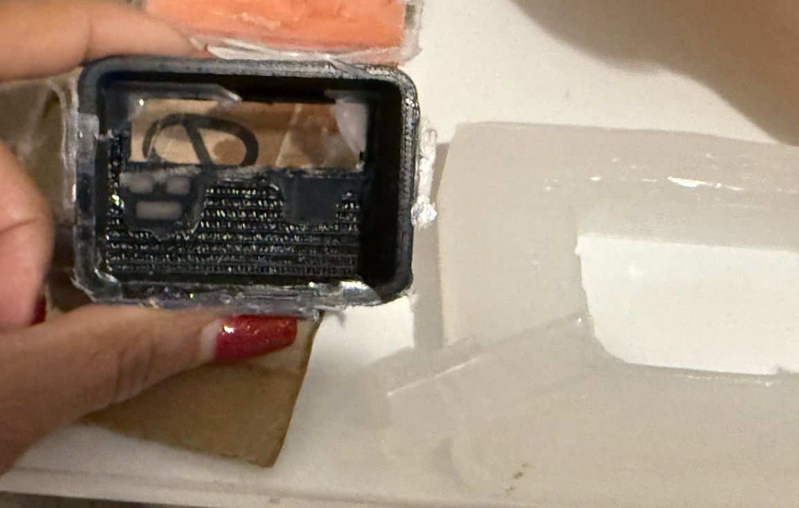
When I woke up, I rushed to my in home lab to check on the final results. To my disappointment, there was even MORE seepage than when I went to bed. I could also tell immediately that there was barely any silicone left on the top of the 3D print. Clearly, my 3d print was not encampsulated and I could tell around the edges that I lost at least 3mm of silicone to seepage. I removed the piece from the larger carboard box to observe the seepage.