Week 2 | Computer Aided Design
Overview
This week I explored 2D and 3D computer-aided design tools to model a version of my final project 2 part design aid. I evaluated several software options, documented my modelling process in Fusion 360 and Prusa Slicer, and learned how to compress images and video files for efficient documentation.
My final project involves a wearable/handheld electronics component. This week's CAD work gave me a clearer sense of the physical form, dimensions, and constraints before I commit to fabrication in later weeks.
Group Assignment
There is not one listed for this week
Individual Assignment
- Evaluate and select 2D and 3D software.
- Demonstrate and describe processes used in modelling with 2D and 3D softwares.
- Demonstrate image and video compression
Softwares Evaluated
Before diving into modelling, I considered which tools were right for what I needed to build this week. The table below shows what I evaluated and why I made the choices I did.
| Software | Type | Did I use it? | Why/Why Not |
| Fusion 360 | 3D Parametric CAD | YES | Best fit for modelling a physical enclosure with precise dimensions. Parametric constraints let me adjust the console shell without rebuilding from scratch. |
| Inkscape | 2d Vector | YES | I knew I would need to practice changing the width of traces of my schematic for use in different materials. Copper board milled with tiny endmills require thinner traces than copper tape that will be milled on a vinyl cutter. The blade of a vinyl cutter requires wider traces. |
| KiCad | 2d Schematics and PCB trace design | YES | I wanted to start practicing designing PCBs and utilize software that is considered standard in the electronics industry. |
| Prusa Slicer | 3D Slicing and Print Previewing | YES | WUsed to estimate print time, check scale, and verify wall thickness before committing to a print. |
2D Design in KiCad : PCB Schematics
My 2D design is directly connected to my final project. I designed a PCB schematic from scratch in KiCad for the wearable component of my final project. My final project is multiple machines. One machine is a device that combines a wearable electronics piece that communicates with a handheld console modelled in Fusion 360 below.
Why KiCad
KiCad is free, open source, and produces industry-standard outputs (Gerber, SVG, DXF). For a wearable PCB that I plan to iterate on throughout Fab Academy, having a fully editable source file in an open format matters more than the convenience of a simpler tool. Plus, I really want to be able to teach KiCad to students at my University and within the Fab Lab that I run. Also, being able to offer this knowledge to innovators within my community is pretty exciting.
My Process
I designed the schematic from scratch using the KiCad Schematic Editor. The KiCad Schematic Editor is a 2D design environment where you place electrical symbols and connect them with wires to define how the circuit works logically. I found this incredibly helpful to be able to start thinking about how it will be physically laid out on a board before even looking at materials.
My KiCad Schematic Steps
- I opened KiCad and created a new project and named it based on my longterm goal of this beign a part of my Final Project.
- KiCad did not have the symbols I needed so I imported the symbols and footprints into the symbol and footprint libray before proceeding.
- I opened the Schematic Editor and began placing symbols
- For each component I plan to use in my wearable I searched the symbol library and placed the corresponding symbol on the page based on where I hope to align it in reality.
- Next I started to map out how components will be connected to others using wires paying close attention to spacing considerations.
- Once I had everything placed I made sure to run the ERC (Electronics Rule Checker). This part was the most frustrating. Since I am teaching myself how to utilize KiCad I had a lot of errors and warnings that I needed to resolve. This portion honestly took me over 5 hours.
- After finally receiving the 0 errors and 0 warnings green light I moved forward to assigning footprints to each symbol using the assign footprints tool within KiCad.
My KiCad PCB Layout from Schematic Steps
- I exited the schematic editor and opened the PCB editor. I went to the toolbar and chose tools then to update the PCB from the schematic in order to easily bring over my work from the schematic editor
- Once I had the components added, I touted the traces between the components beign sure to avoid crossing any wires.
- I set the trace width to .08mm and plan to adjust that depending on what machine i'm using in the future using inkscape.
- I drew the board outline based on the rough sketch I created of the wearable. I hope in the future for the wearable to be pretty small, right now I think its senseble enough for a prototype.
- I ran the DRC (similar to the ERC, the design rules check) and thankfully received no errors.
- Next I was ready to export this design as an SVG. I went to file, export, SVG.
- Within the SVG export box, I made sure to only select F.cu, and edge cuts. I then saved it to my project folder.
Trace Width Adjustments in Inkscape
- I imported the SVG into Inkscape
- I went throug each trace, made sure to choose stroke to path first, then opened the fill and stroke section of inkscape. I widened each of the traces to 8mm.
- Next I made adjustments based on what was looking a little wonky. Some of the lines were overlapping, some just didn't turn in ways that remind me of what a circuit board should look like.
- I saved the final adjusted files in the same folder as the other files for the wearable and made sure to save it as a file type that aligns with vinyl cutters (svg)
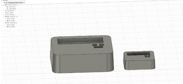
Prototyping My Handheld Console in Fusion 360
Tools and Software
| Tool or Software | Purpose |
| Fusion 360 | Modeling my final project prototype |
| Prusa Slicer | 3D modeling of console, estimating time requirements |
| Prusa MK3S+ | Printing Mini Prototype |
Fusion 360: Designing the Console
- Sketch: Create a new sketch on the Top Plane.
- Rectangle: Draw a Center Rectangle from the origin: 95mm x 85mm
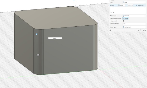
- Extrude: Press E and extrude it upward by 60mm.
- Fillet: Press F. Select the four vertical corner edges and give them a 10mm radius to make it handheld-friendly.
Creating the Console
- Sketch on Top Face: Select the top surface of your block and create a new sketch.
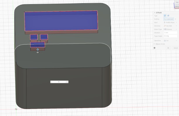
- LCD Window: Draw a Center Rectangle near the top half: 72mm x 25mm (this is the visible area of a 1602 LCD).
- Button Holes: Draw two circles (diameter 7mm) below the LCD window where you want your "Advance" buttons to sit.
- Extrude Cut: Press E, select the rectangle and circles, and extrude downward by -5mm (this creates the indentations for your cast).
Creating The Spaces for Future Buttons and Screens
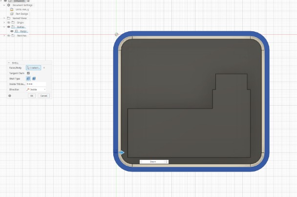
- Shell Command: Go to Modify > Shell.
- Select the BOTTOM face of the block.
- Inside Thickness: Set to 3mm. This hollows out the inside so your electronics have a home.
Create the Interior Cavity (The "Void")
- Right-click the body in the browser tree and select "Create Components from Bodies".
- Right-click component from the browser tree.
- Select "Copy".
- Deselect components by clicking outside the browser tree in the workspace of Fusion.
- Right-click the workspace of Fusion.
- Select "Paste New".
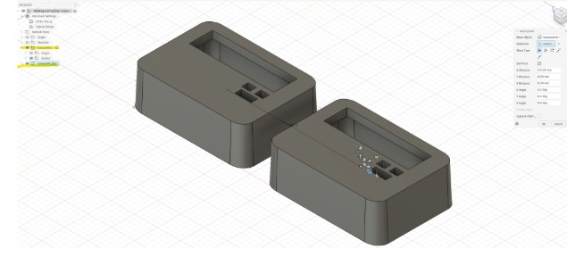
- The Move arrows will come up, move the second component away from the original
- Go to Modify > Scale.
- Selection: Click on the second console body (or select it from the browser on the left).
- Point: Select a corner of the model or the center origin. This is the "anchor" point it will shrink toward.
- Scale Type: Ensure this is set to Uniform.
- Scale Factor: Type 0.5.
- Click OK.
Create a Half-Scale Model for Prototype Testing
- In the Browser on the left, right-click your Component or Body.
- Select Save as Mesh (or Export > STL).
- Set Refinement to High.
- Open in your slicer (PrusaSlicer) and start the print!
Export for Printing
Image and File Compression
Fab Academy requires that all images and videos are compressed before uploading to the class archive. Large files bloat the repo and slow down evaluator clones. Below I document the tools and methods I used and show before/after file sizes.
Image Compression
I started using the website tiny.jpg during Fabricademy and also plan to use it in this course as well.
Steps for using Tiny Jpg
- Navigate to the website Tiny Jpg
- I upload the file or files I'd like to resize
- Tiny Jpg resizes the file for me, then I download the file
Reflection
What I learned this week
Working in Fusion 360 forced me to think about the console as a series of constrained relationships rather than a fixed shape.
What the 3D model revealed about my final project
The model made clear that the button placement I had sketched in Week 1 was too narrow. I revised the sketch before moving forward.
Files
| File | Description | Inkscape Traces — Week 2 | Inkscape Traces |
| Schematic — Week 2 | KiCad Schematic |
| Console Prototype — Fusion 360 | Fusion 360 Console Prototype |
| Console V1 — Prusa Slicer | Prusa Slicer GCode |