

CNC Milling
Milling is a machining process that removes material using a rotating cutting tool called an end mill. The tool spins at high speed while moving across the material, gradually cutting layers until the desired geometry is achieved.
This process is performed using a CNC machine (Computer Numerical Control), meaning that all movements, speeds, and operations are controlled through G-code instructions.
⚙️ Workflow
The general workflow for CNC milling goes from digital design all the way to physical part. Click each step to see more details.
✏️ Step 1 — CAD Design
- Model the part in a CAD software (Fusion 360, Inventor, Rhino, etc.)
- Define all geometry, slots, holes, and interlocking features
- Use parametric design so dimensions can update automatically if material or tool changes
- Although designs can include 3D geometry, cutting and engraving operations are commonly referred to as 2D machining operations
🛤️ Step 2 — CAM Process
- Define toolpaths — the exact paths the cutting tool will follow
- Select the appropriate milling tool (diameter, flutes, material suitability)
- Choose a machining strategy: pocket, contour, drill, 3D surfacing, etc.
- Configure cutting parameters: feed rate, plunge rate, spindle RPM, depth of cut
📄 Step 3 — G-code Generation
- The CAM software exports G-code — a text-based set of instructions the CNC machine will execute
- G-code controls every movement: position, speed, spindle on/off, tool changes
- The file is transferred to the machine controller (e.g. enRoute software for the MultiCam)
- Always verify the simulation before running on the actual machine
🪵 Materials
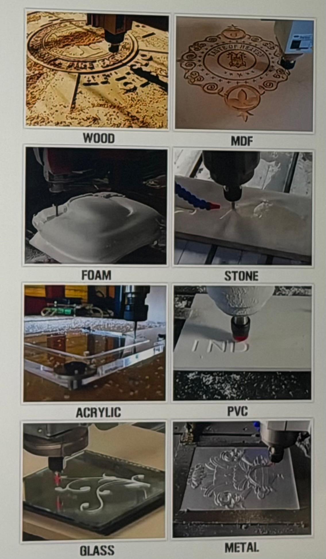
A CNC router can work with a wide variety of materials. The table below summarizes the most common categories. For this assignment we used MDF and Plywood.
| Material Type | Examples |
|---|---|
| Wood | MDF, Plywood, Solid wood |
| Plastics | Acrylic, PVC, Polymers |
| Foam | Foam board |
| Engineering Plastics | Nylon, Polycarbonate |
| Others | Non-ferrous alloys |
Regardless of the material, it is essential to verify the actual thickness with a caliper.
In our case: Board thickness = 9 mm. In the CAD/CAM model we typically program 9.x mm to ensure the tool cuts completely through — avoiding uncut material at the bottom.
⚠️ Internal Corners & the Dog-Bone Technique
Because milling tools are cylindrical, they physically cannot produce perfectly sharp internal corners. Instead, the tool leaves a rounded internal radius (fillet) equal to the tool radius. This means a milling machine can never produce a perfect 90° internal corner.
To solve this limitation, designers use the Dog-Bone technique: small circular cutouts are added at internal corners so that assembled pieces can fit together properly — resembling a dog bone shape.
A critical practice is to align the center of the relief circle exactly with the internal corner:
Parts fit flush with no visible gap between them. Clean, professional result.
A small gap appears between parts. The joint won't seat correctly.
Even though it is a small design detail, proper dog-bone placement greatly improves the quality of the final assembly.
🏎️ CNC Speed Parameters
CNC machines operate along three axes: X, Y, and Z. Each axis has specific speed parameters controlling how the tool moves during machining. Units are mm/min for feed speeds and RPM for spindle speed.
The speed at which the cutting tool moves along the X and Y axes while cutting material. Too fast can cause tool breakage; too slow can burn the material.
The speed at which the tool moves vertically (Z axis) to enter the material. Generally set lower than feed rate to protect the tool tip.
How fast the spindle rotates the cutting tool. Metals typically require lower RPM; wood and plastics vary by tool diameter.
Speed used when the tool moves without cutting, usually repositioning between operations. Much faster than feed rate.
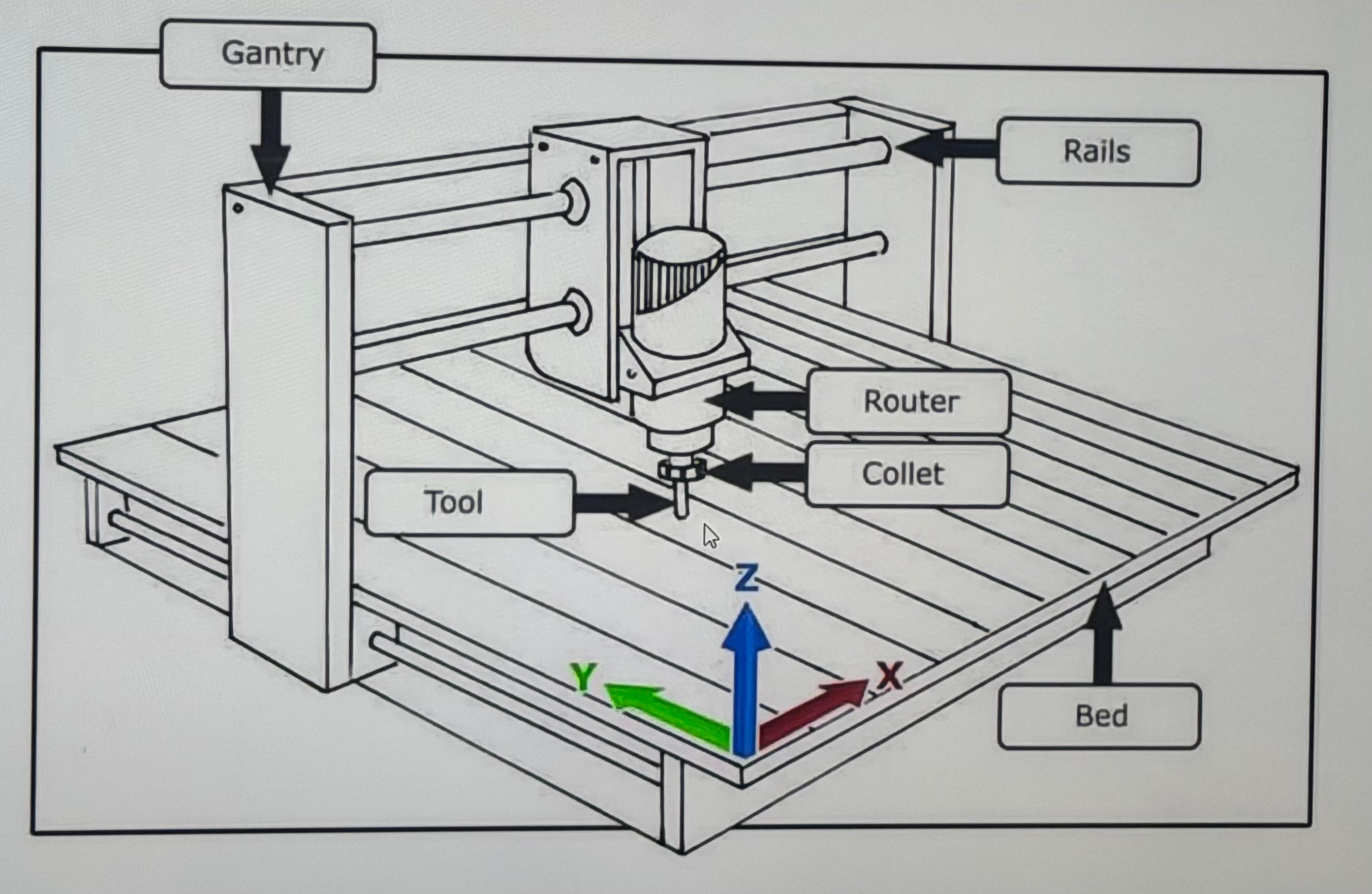
🔩 Tool System & Milling Bits
Between the spindle motor and the cutting tool there is a component called a collet, which holds the tool securely in place. The collet diameter must match the tool shank diameter exactly.
Common Milling Tool Types
Used for creating circular holes in the material. Designed to plunge vertically.
Used for removing large amounts of material and performing general cutting operations. The most common tool for CNC routing.
Used for creating threaded holes directly in the material for mechanical fasteners.
- Tool diameter
- Total length
- Cutting diameter
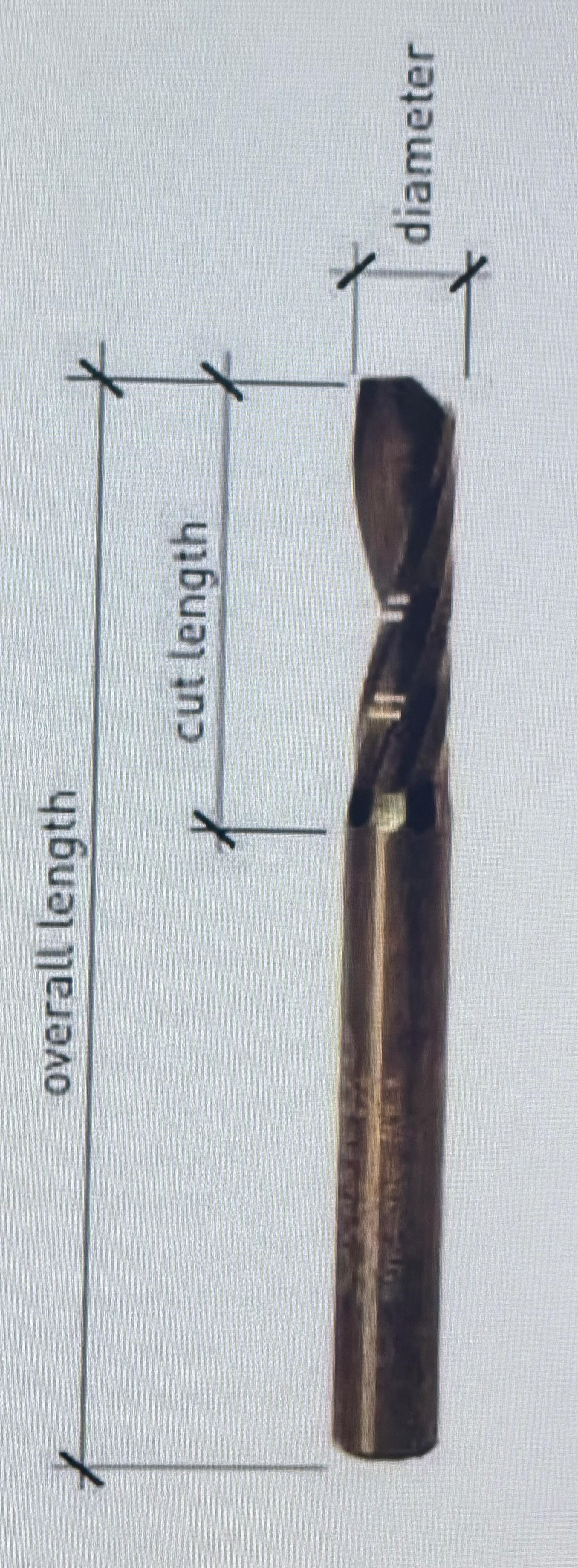
For this assignment: We used a 6 mm flat end mill.
Lab Safety & Machine Process
For the group assignment, our team completed comprehensive safety training and conducted systematic testing of the MultiCam 3000 CNC Router. We evaluated critical machine parameters including runout accuracy, fixturing methods, cutting speeds and feeds, material compatibility, and toolpath strategies to establish best practices for the lab.
My individual contribution focused on three key areas:
I designed and parametrically modeled three different corner relief approaches (Dog-Bone, T-Bone, Semi Dog-Bone) in Fusion 360 to systematically evaluate their assembly performance and aesthetic quality.
I compiled detailed documentation of the MultiCam's key components, operation procedures, and calibration methods — including step-by-step Z-axis calibration on both vacuum bed and material surface.
I conducted physical tests on MDF to determine optimal feed rates, plunge rates, and finishing quality while maintaining tight tolerances for interlocking joint assembly.
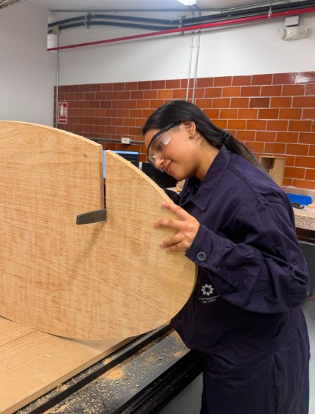
🦺 Safety Measures
Before starting any project involving the milling machine, it is essential to use proper personal protective equipment (PPE) to ensure the safety of everyone in the workshop.
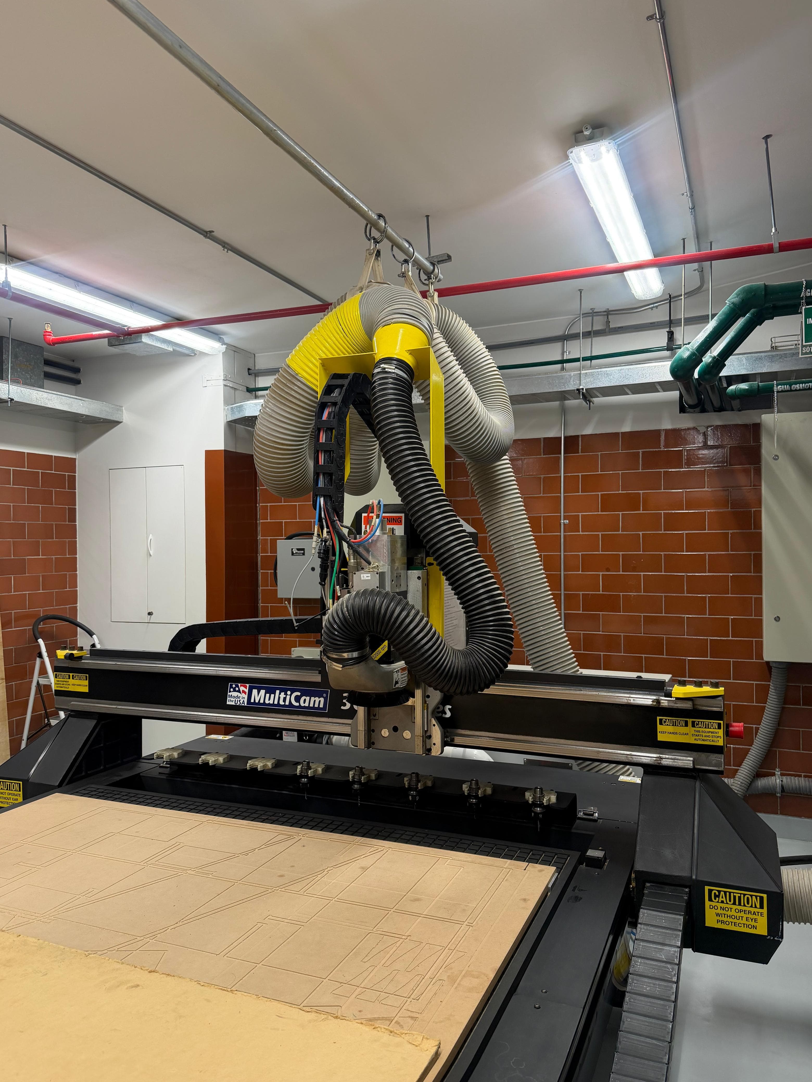
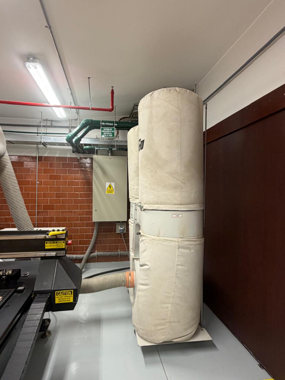
🏭 MultiCam 3000 — Our Lab's CNC Router
At our Fab Lab we use the MultiCam 3000, a 3-axis CNC router (X, Y, Z) that uses rotating cutting tools to remove material. One key advantage of this machine is its ability to automatically change tools during the machining process.
| Feature | Description |
|---|---|
| Cutting types | 2D, 2.5D and 3D |
| Materials | MDF, plywood, aluminum, foam, solid wood |
| Maximum thickness | Depends on the tool; can exceed 50 mm |
| Precision | High (~0.1 mm) |
| Finish | Clean edges without burning |
| Speed | Slower than laser for simple 2D cuts |
Key Machine Parts
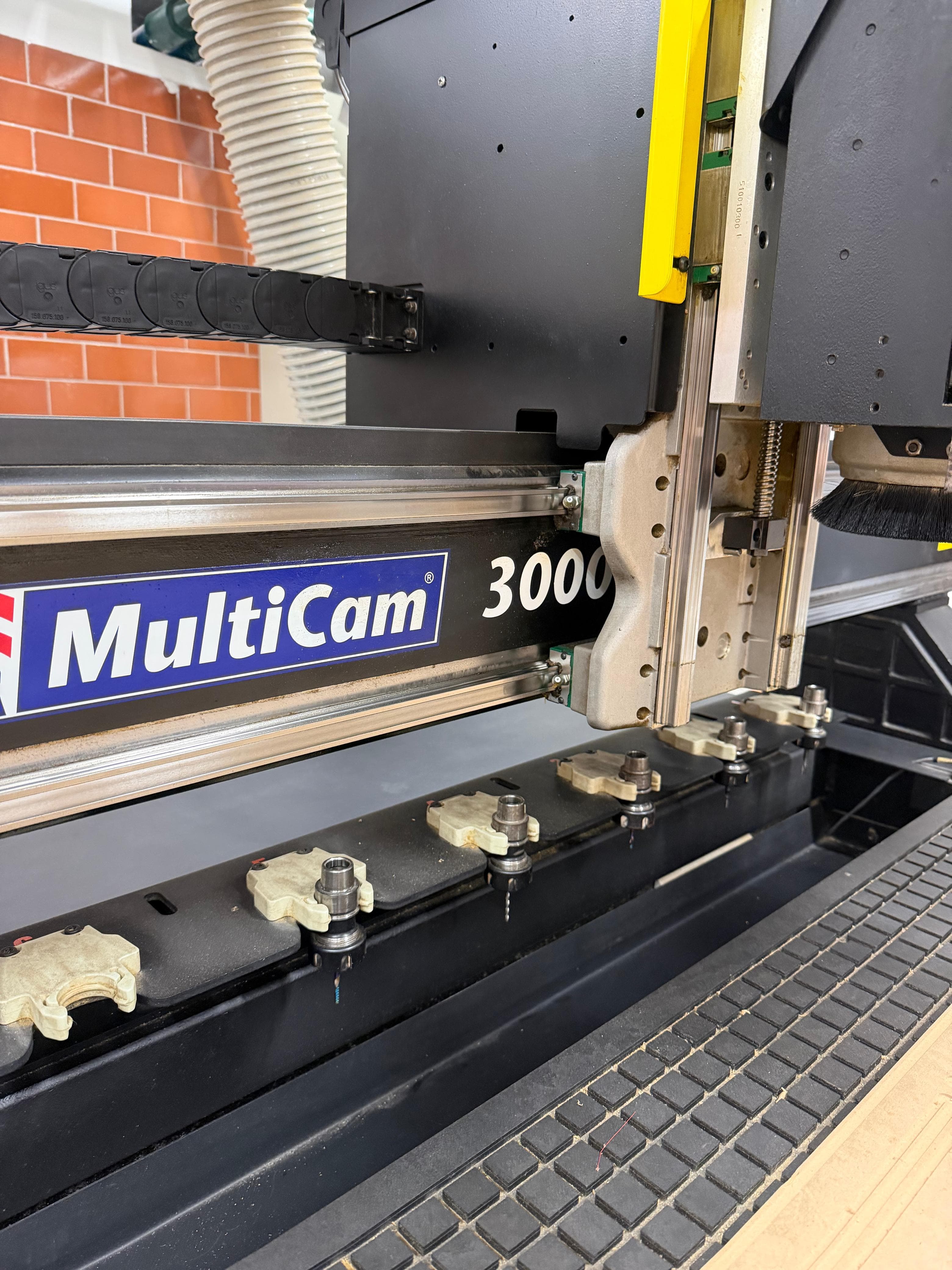
The MultiCam contains a tool-changing table with a carousel for storing multiple bits, and a vacuum bed (cama de succión) that holds the workpiece firmly against the cutting surface during machining.
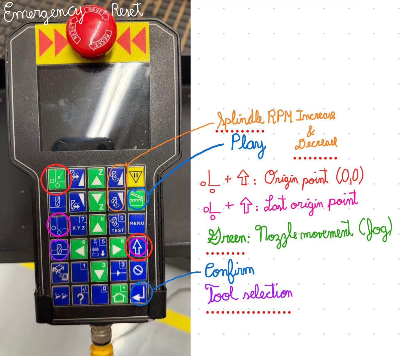
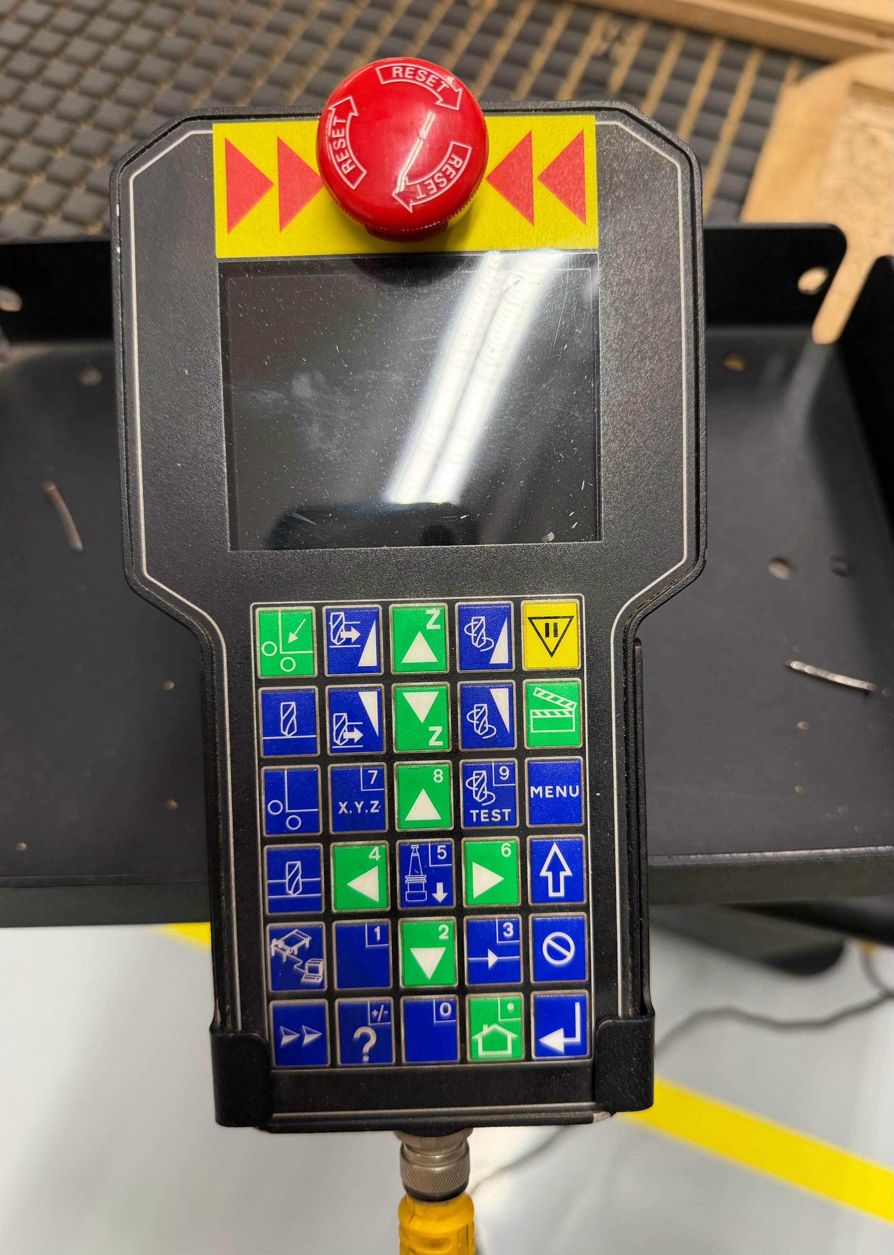
The Key Pad is the handheld controller used to operate the MultiCam manually. It allows the operator to jog the machine along all three axes (X, Y, Z), set the work origin, calibrate tool height, run the machining program, and perform emergency stops. All machine setup operations — including Z-axis calibration on both the bed and the material surface — are performed through this controller before sending the machining file.
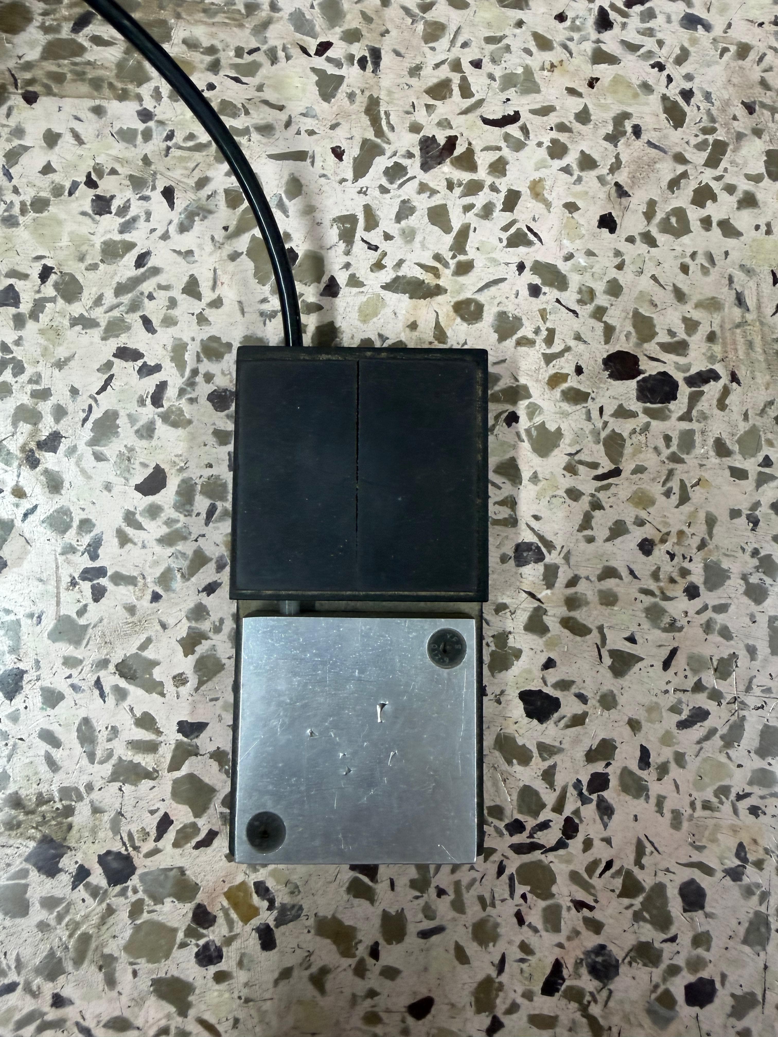
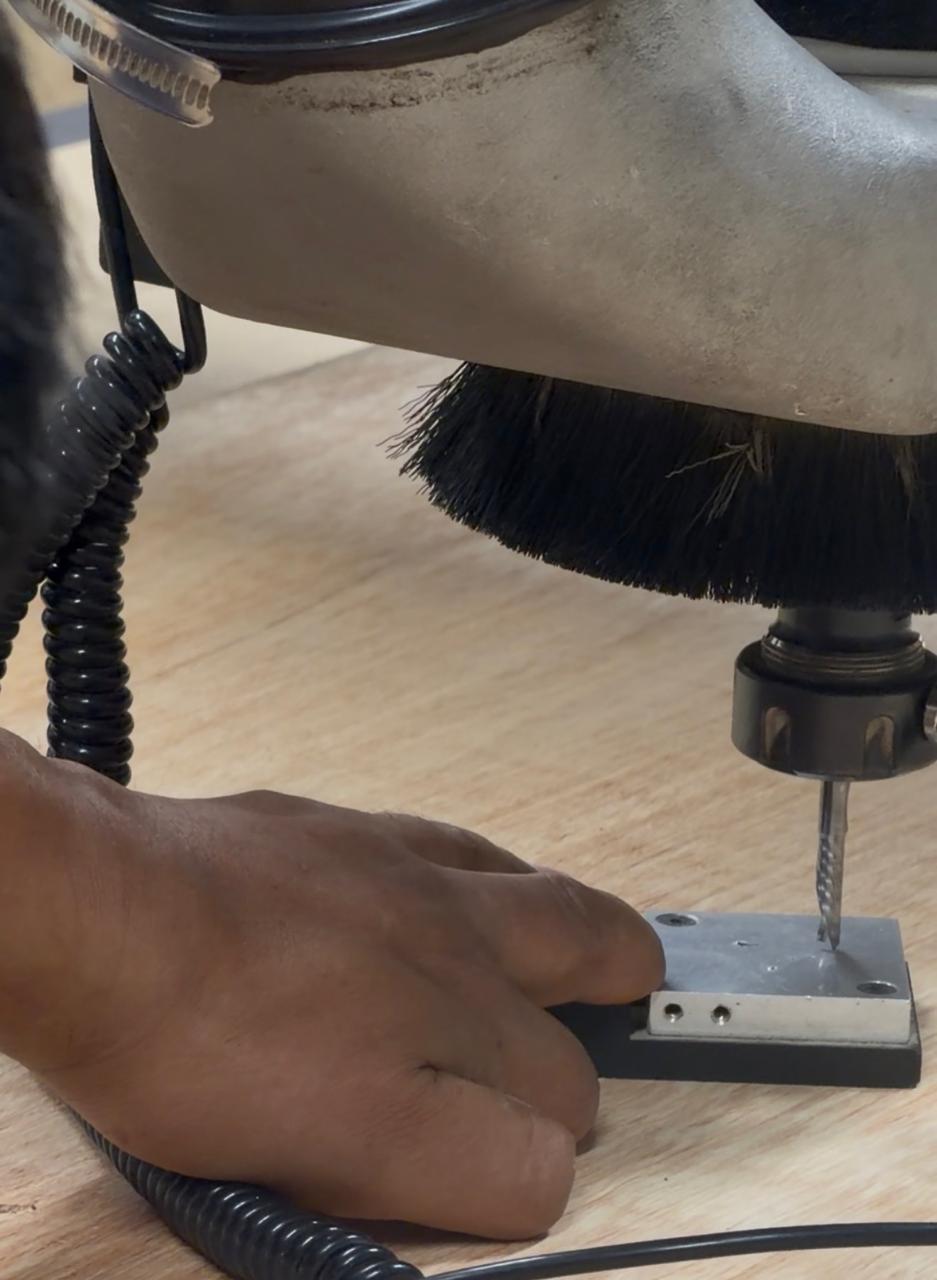
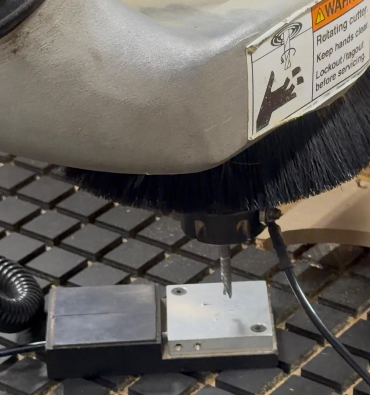
The ground clip is used to calibrate the Z-axis relative to both the material surface and the vacuum bed surface. When the tool tip makes contact with the calibration plate, the machine detects the electrical circuit closing and records that position as the reference height. This ensures the tool knows exactly how deep to cut into the material.
🔧 CNC Milling Process — Step by Step
Before starting, we always establish an origin point as the reference for all machine movements.
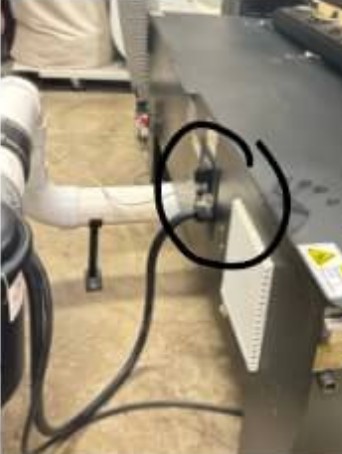
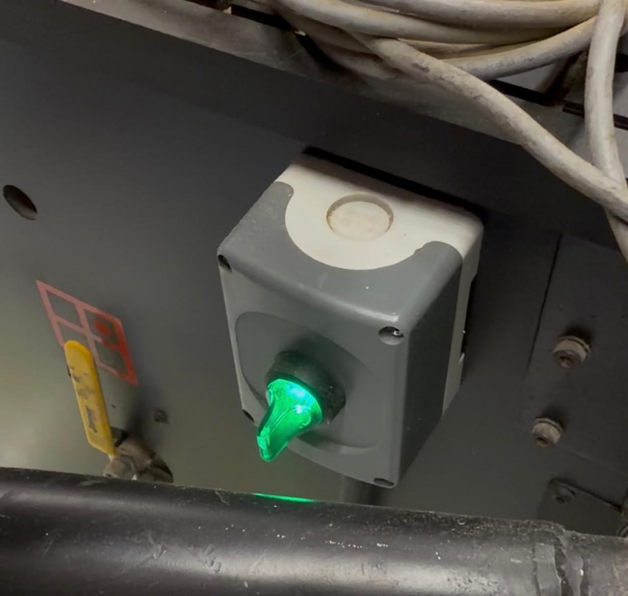
The machine is turned on using the main power switch located at the back of the unit.
Using the key pad, the Z-axis is calibrated on the vacuum bed surface first — this sets the machine's safety lower limit and establishes the reference for total material thickness.
The vacuum suction system is activated to hold the board firmly against the bed and prevent any movement during machining. The Dust Extraction Hood removes chips and debris produced during the cutting process, keeping the workspace clean and the workpiece visible.
After placing the material on the bed, the tool height is calibrated again — this time on the material surface. This tells the machine exactly where the top of the material is, ensuring accurate depth-of-cut calculations.
For additional stability — especially when machining thin or narrow parts — the board can be screwed down to the sacrificial bed. This prevents any lifting or shifting that could occur as the vacuum alone might not hold all areas of the material equally.
The design file (DXF) is transferred to the machine through enRoute — the CAM software installed on a laptop connected to the MultiCam. In enRoute, the toolpaths are verified, machining parameters are set, and the G-code is generated and sent to the machine controller for execution.

Internal Corner Relief Strategies
For my individual contribution to the group assignment, I focused on modeling the different corner strategies in Autodesk Fusion 360, creating parametric sketches to control key dimensions, and running simulation tests to observe how the joints behave during assembly.
When machining parts with a CNC router, internal corners cannot be perfectly sharp because the cutting tool is cylindrical. This leaves a radius in the pockets or slots — when assembling square components, the rounded internal corner prevents the part from fully fitting.
To solve this, designers use corner relief strategies that add small circular cuts at internal corners, creating enough clearance for square parts to properly seat during assembly.
The center of the relief circle is placed directly at the internal corner, extending diagonally outward.
- Center coincides with corner
- Relief extends diagonally
- Maximum clearance
- Most visible relief
The circle center is aligned with one edge of the rectangle rather than the corner, extending along a single axis.
- Center on edge extension
- Relief on one axis only
- Less material removed
- Cleaner visual result
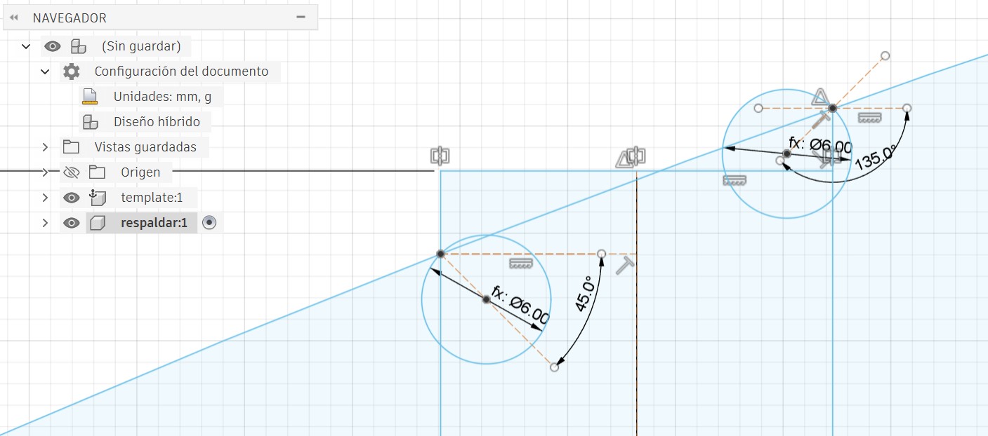
The circle is offset from the corner — the corner touches the circumference rather than the center, leaving only part of the circle visible.
- Circle offset from corner
- Corner touches circle edge
- Most discrete relief
- Best aesthetic finish ✅
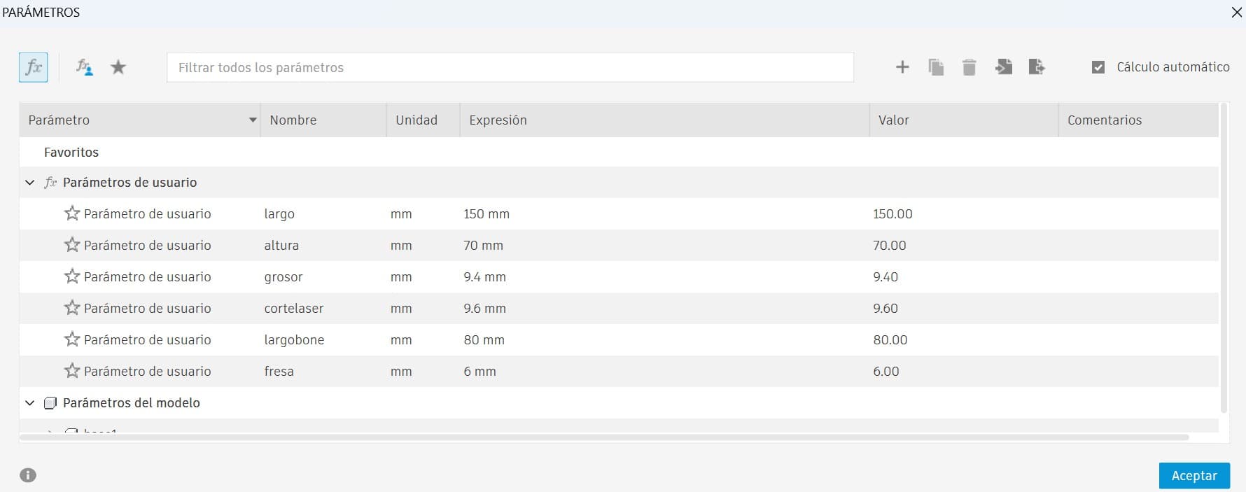
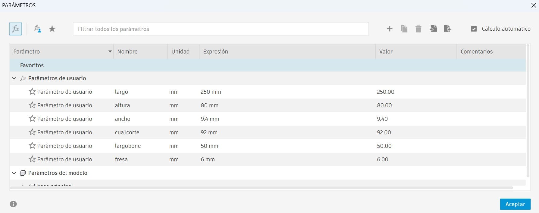
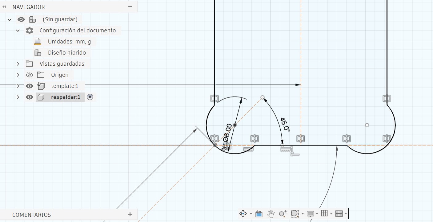
📐 Parametric Simulation in Fusion 360
Using parametric design ensures that if the tool size or material changes, the geometry can update automatically without needing to redesign the model.
- Tool diameter: 6 mm
- Material thickness: 9.4 mm
- Joint dimensions based on tool radius
- Project Geometry
- Coincident Constraint
- Tangent Constraint
- Construction Lines
- Midpoint Constraint
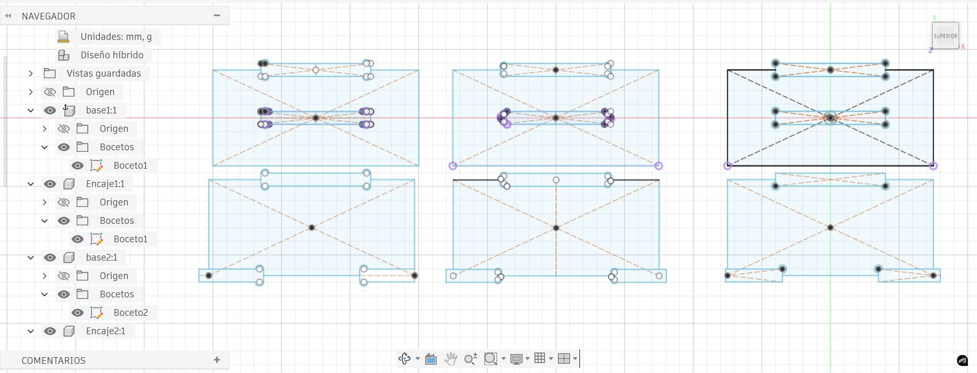
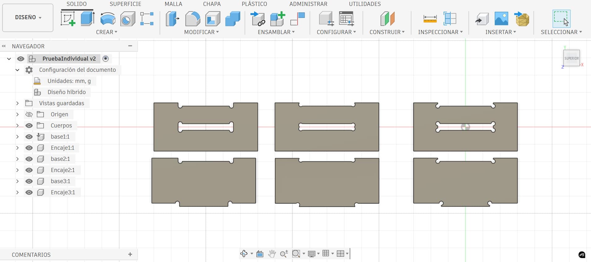
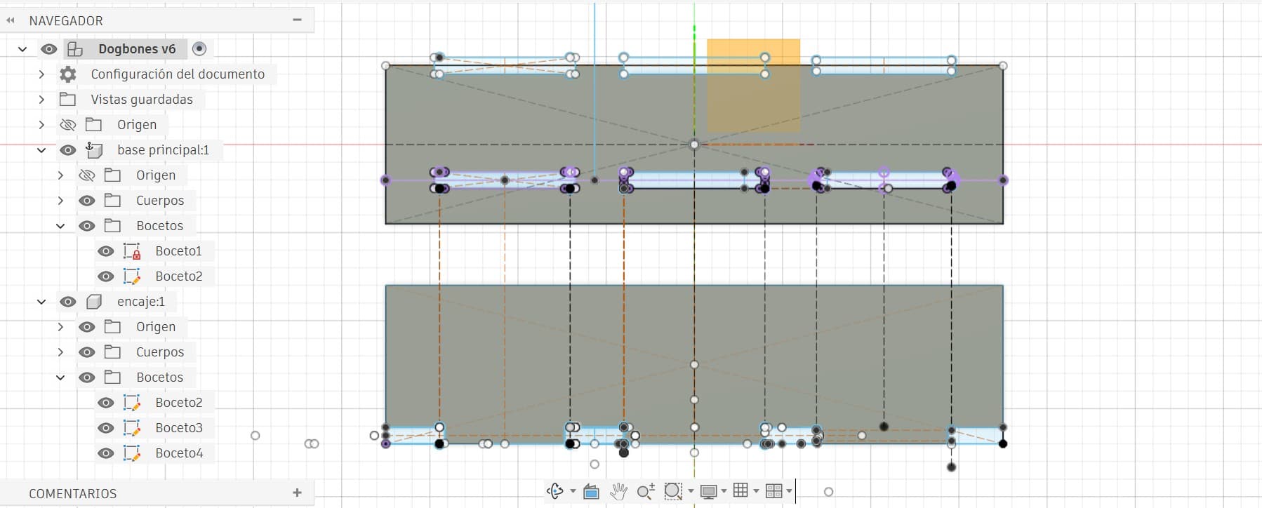
Test 1 — Individual Bone Tests
Each corner relief strategy was analyzed individually to evaluate how the joints behave during assembly. The mating parts were designed so that they engaged with approximately half of the bone relief — allowing observation of how each strategy affects fitting and clearance.
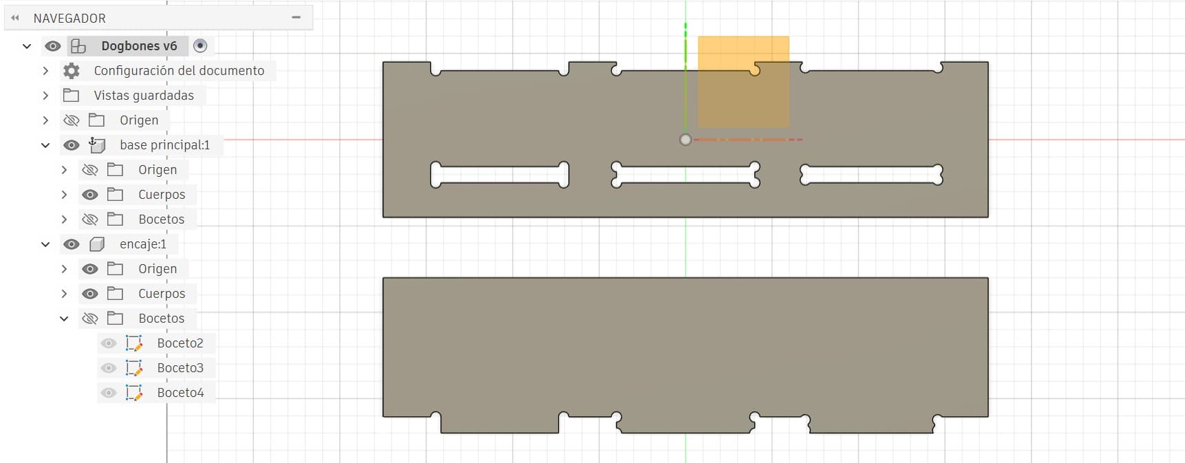
Test 2 — Combined Bone Test
A single test board containing all three corner relief strategies was designed so that the joints engaged with more than half of the bone relief, allowing comparison of all strategies under slightly different fitting conditions.
Exporting to enRoute via Inventor
Both projects were exported to Autodesk Inventor to create the DXF file. This file was then transferred to enRoute CAM software, where the parameters for generating the G-code were configured.
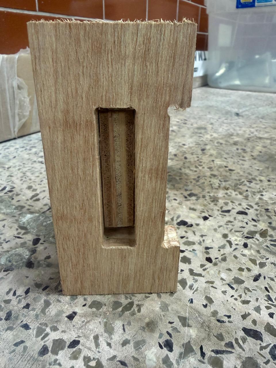
Tabs (bridges) are small connections that keep the final piece attached to the board during machining, preventing it from moving or breaking free while the cut finishes. They are small uncut sections left intentionally along the contour.
After machining is complete, the tabs are cut manually with a chisel or flush-cut saw, and the piece is then separated cleanly from the board.
📊 Test Results
The final results of both machined tests are shown below:
As clearly demonstrated by the test results, the strategy that produced the best outcome was the Semi Dog-Bone.
- Better aesthetic finish — relief is far less visually noticeable
- The circular cutout blends more naturally into the geometry
- Maintains sufficient clearance for proper assembly
- Ideal for furniture and visible components
🔄 Fusion 360 → Inventor → MultiCam Workflow
Since I have more experience with Autodesk Fusion 360, I designed all parts there. However, Fusion does not provide a straightforward way to export only a single face of a solid body as a DXF file. Because of this, I export each part as a STEP file and open it in Autodesk Inventor, where extracting a face as DXF is easier.
In Fusion 360:
- Export each part separately as
.STEP(or .DXF if applicable)
In Inventor:
- Import the STEP file
- Switch to Top View (plan view)
- Extract the required face
- Export that face as a
.DXFfile - ⚠️ Before exporting, remove any duplicated or overlapping lines
In MultiCam / enRoute:
- Import the DXF file
- The geometry will be ready to generate toolpaths and G-code
Oval Rocker Chair
For this assignment, I had to design and fabricate something large — at least one dimension measuring one meter or more. From the beginning, I wanted to create something useful for my home: visually appealing with a minimalist, clean aesthetic, and easy to assemble and transport from the Fab Lab.
I searched for inspiration and explored chairs, laptop tables, coat racks, and benches. One design caught my attention immediately because it was similar to the interlocking construction I used during Week 2 with the laser cutter.
→ Go to Week 2: Laser Cutting🪑 The Oval Rocker — Inspiration
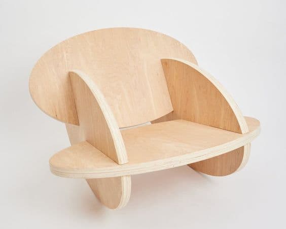
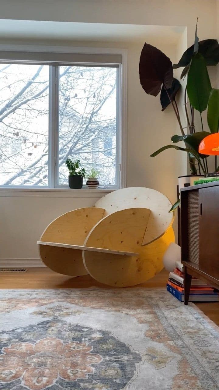
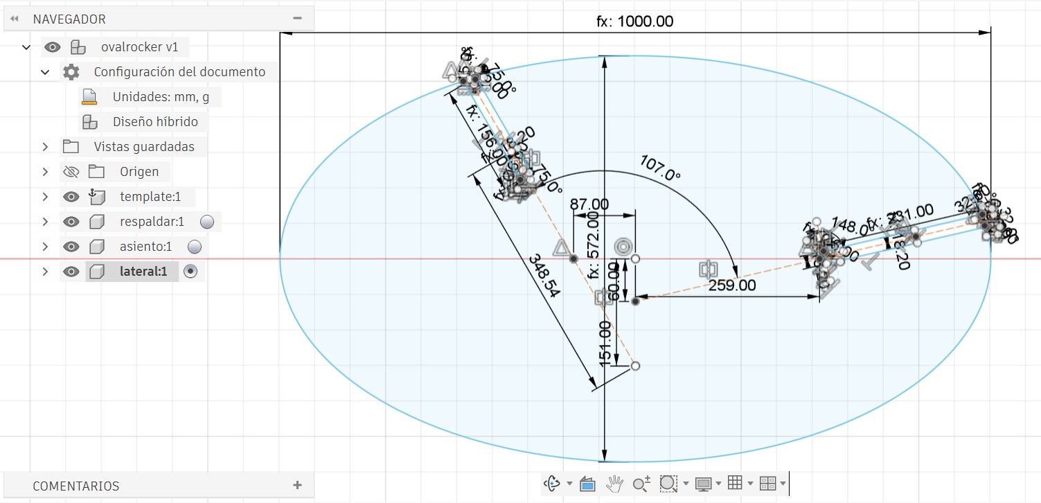
The Oval Rocker is a rocking furniture design created by Andrew Doxtater. It explores the concept of continuous curved motion through an oval-shaped base that allows the structure to rock smoothly in multiple directions, unlike traditional rocking chairs that mainly move forward and backward.

The design stands out for its minimalist structure and the way it uses simple geometric forms to create smooth, balanced movement. A key aspect is the precise geometric relationship between the oval base and the supporting structure, which determines the stability and behavior of the rocking motion.
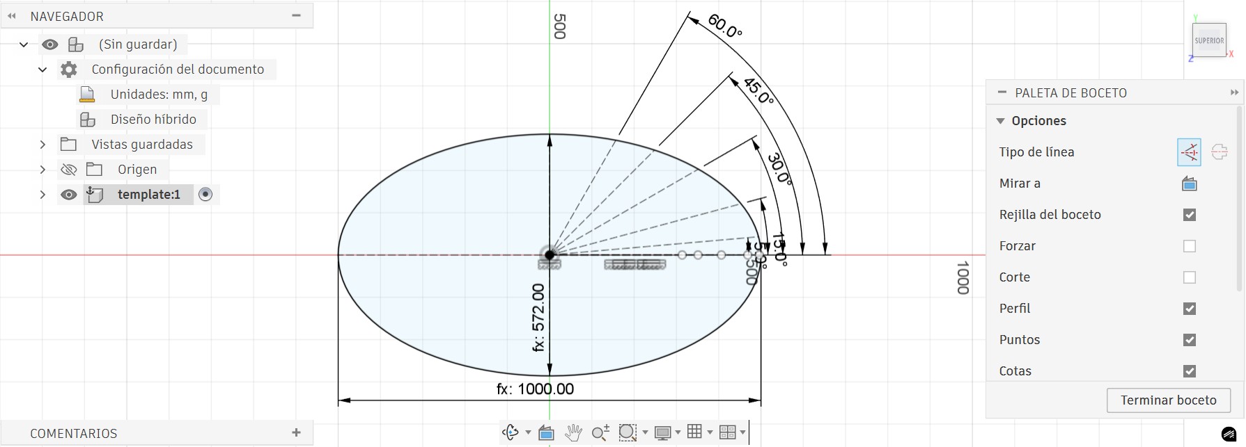
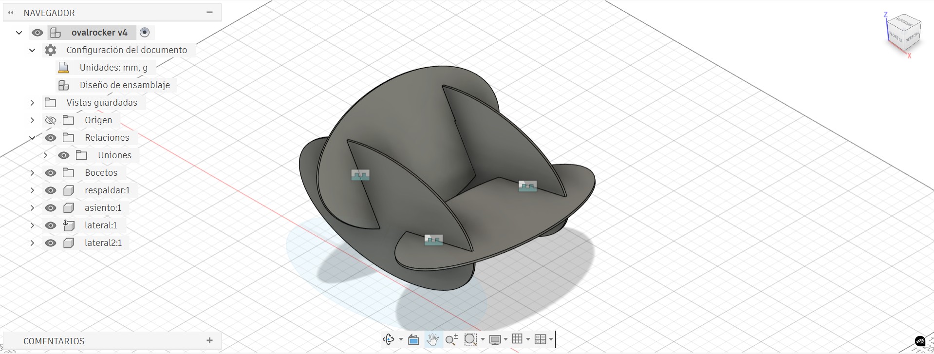
✏️ Design in Fusion 360
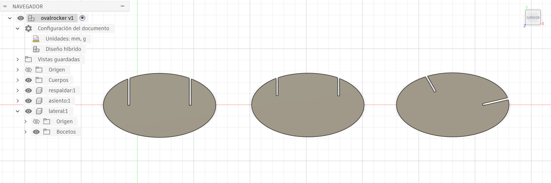
Once the dimensions were determined — including the material thickness — I proceeded to design all parts in Fusion 360. I decided to use Semi Dog-Bone reliefs throughout for the best aesthetic finish and sufficient clearance for assembly.
- Better aesthetic finish
- Relief is more discreet and less visually noticeable
- Maintains sufficient clearance for proper assembly
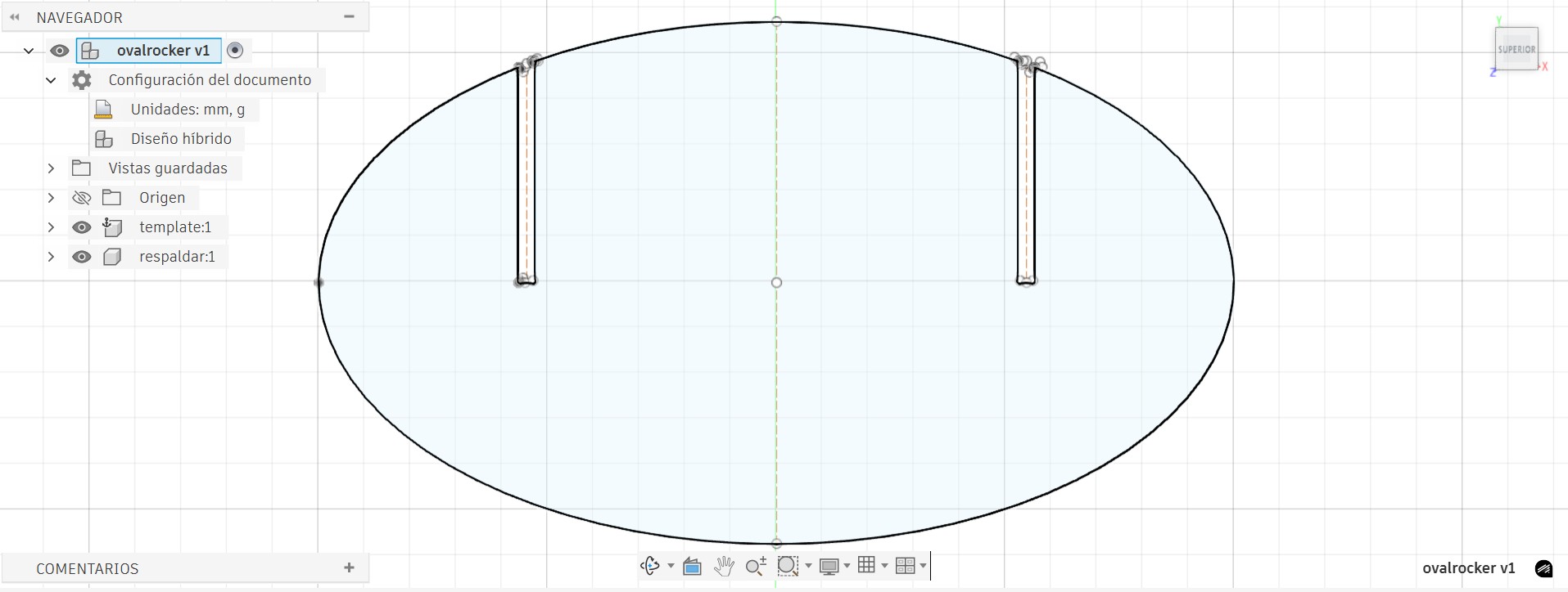
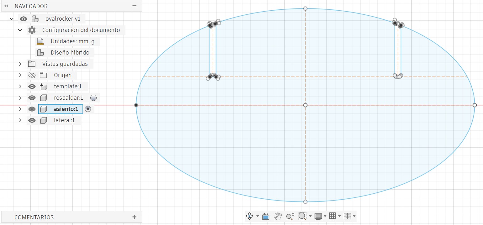
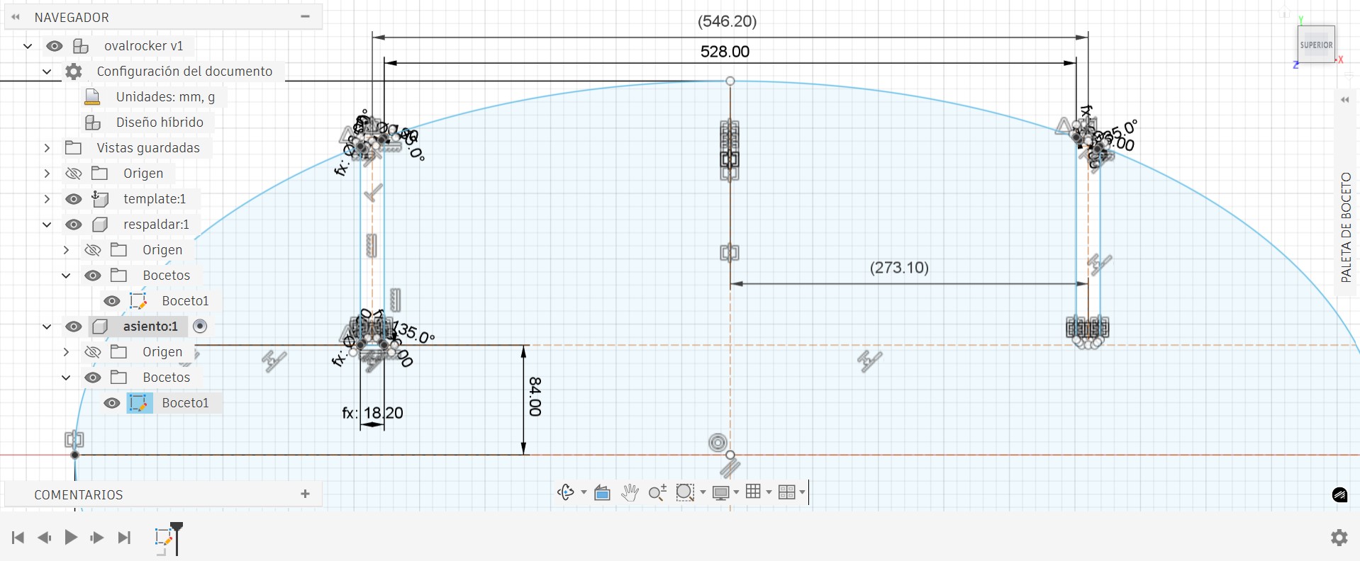
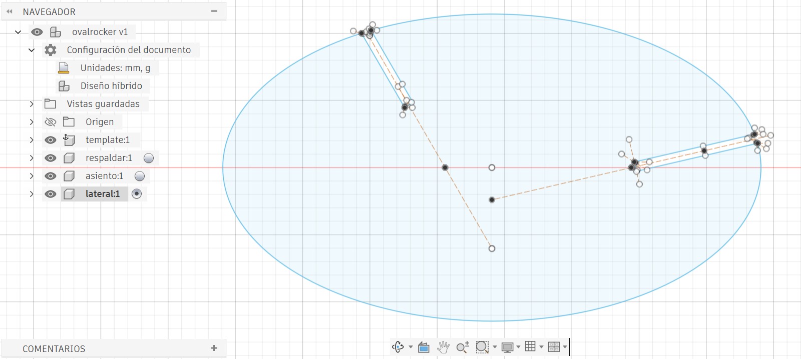
All Parts Together & Assembly Preview
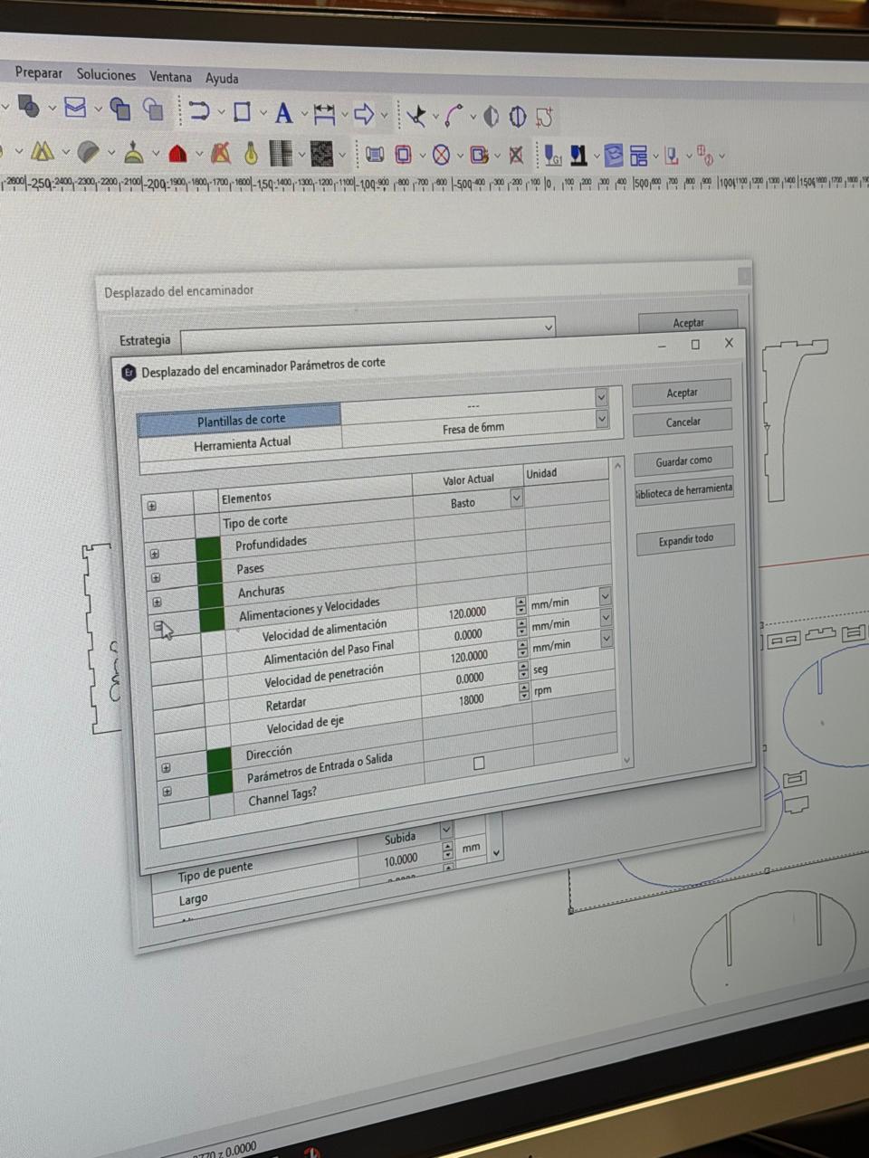
⚙️ Machining Parameters & G-code
In the enRoute program we can visualize the G-code generated from our design before sending it to the machine.
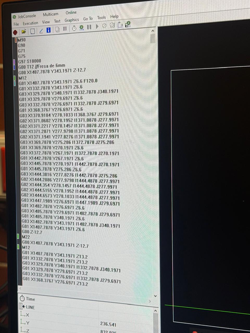
G-code is a text-based language that tells the CNC machine exactly where to move, how fast, and what to do. The most common coordinate letters are:
| Axis / Code | Meaning | In CNC Terms |
|---|---|---|
| X | Left ↔ Right | Horizontal movement along the length of the bed |
| Y | Front ↔ Back | Horizontal movement along the width of the bed |
| Z | Up ↕ Down | Vertical movement — controls cutting depth |
| F | Feed Rate | Speed of the move in mm/min |
| G00 | Rapid Move | Fast repositioning without cutting |
| G01 | Linear Move | Controlled cutting move in a straight line |
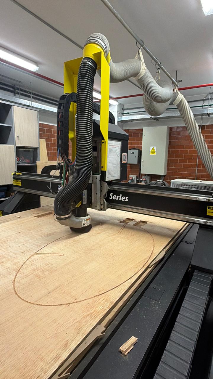
🏭 Cutting in Progress
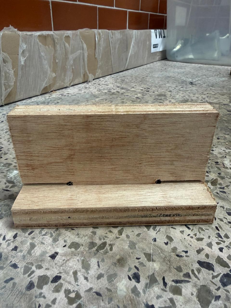
Final Assembly
After all parts were cut and the tabs manually removed, the pieces were assembled — no fasteners, no glue — just the interlocking joints.