
What is
Computer-Aided Design?
Computer-Aided Design (CAD) is the use of computers to assist in the creation, modification, analysis, and optimization of designs. CAD includes both 2D and 3D tools, which are used depending on the design requirements.
CAD can be categorized by the way it represents space, such as 2D drawings, parametric solid modeling, surface modeling, and mesh-based modeling, each suited for different design and fabrication purposes.
Parametric modeling is based on dimensions and parameters that define the geometry. It allows controlled and editable designs in both 2D and 3D, where changes in parameters automatically update the model. This is one of the most powerful concepts in modern design—if you change one dimension, the entire model updates automatically, maintaining all the relationships you've defined.
The Sketch of the
Final Project
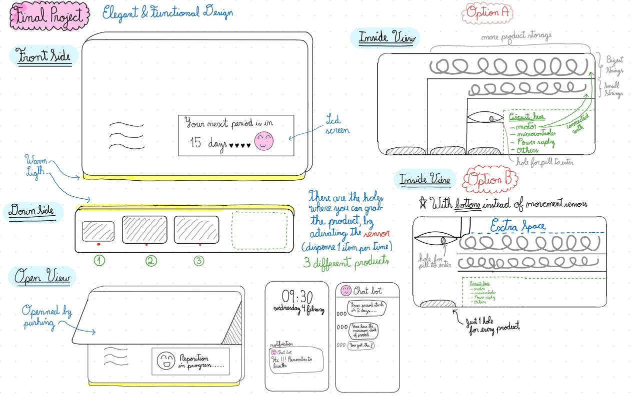
The idea was to create an intelligent menstrual cycle dispenser for personal use. To do this, I first needed to build a clear structure in my mind. In order to organize my ideas and imagine how the product would work and look, I started by drawing it using raster graphics, then vector graphics, and finally modeling it in 3D. In other words, the sketch I made in Week 1 was brought to life in both 2D and 3D.
And to keep everything organized, I created a dedicated project folder, so that all files were easily accessible as I worked on the modeling within the software.
2D Design
Raster & Vector Graphics
2D design focuses on creating flat representations using width and height. It is commonly used for sketches, technical drawings, vector graphics, and layouts that serve as the foundation for fabrication processes such as laser cutting, CNC machining, and as a base for 3D modeling.
In this week's class, I learned that raster and vector graphics differ in how images are defined and scaled. Each one also has a different minimum unit: raster graphics are based on pixels, while vector graphics are based on points.
During this week, I also tried to sketch my final project using both methods.
Raster graphics are composed of pixels, so they lose quality and become pixelated when zooming in. Raster design is more freeform and suitable for artistic or image-based work. GIMP and Krita are examples of raster-based software used for 2D design.
GIMP Essential Tools
To move layers, selections, and objects.
To resize images or specific elements.
To draw, color, and retouch images.
To organize and edit different parts separately.
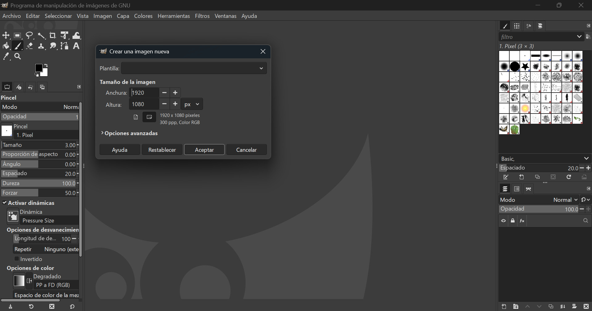
First, I opened GIMP and selected "New" >> "New...". Then, I chose the image dimensions I wanted to create. In this case, I left the standard measurements shown in the image.
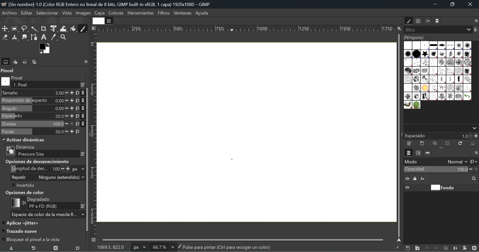
GIMP has an interface mainly divided into three areas: on the left is the toolbox, where you can select, draw, move, transform, or erase, and below it are the options for the active tool; in the center is the canvas, and on the right are the panels, especially the Layers panel, which is the most important, along with Channels and Paths. These panels are used to organize the image and control opacity, order, and visibility.
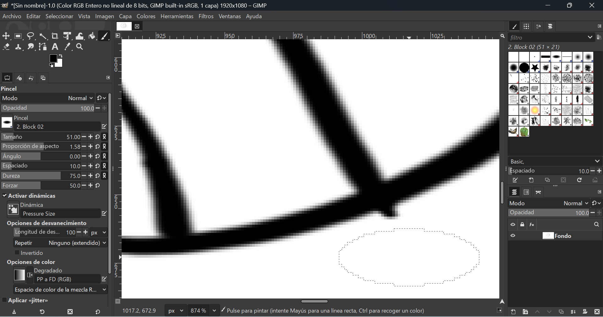
I tested the raster function by drawing a simple smiley face to understand how the tool works and get familiar with the brush settings.
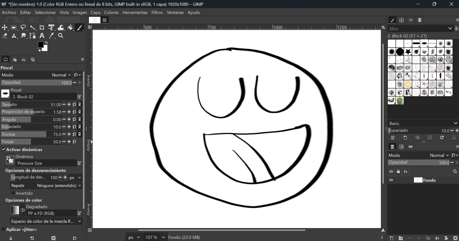
Then I zoomed in, and it was clear that the pixels became visible and the smooth pencil finish had disappeared. This is the fundamental difference with raster graphics—they are resolution dependent.
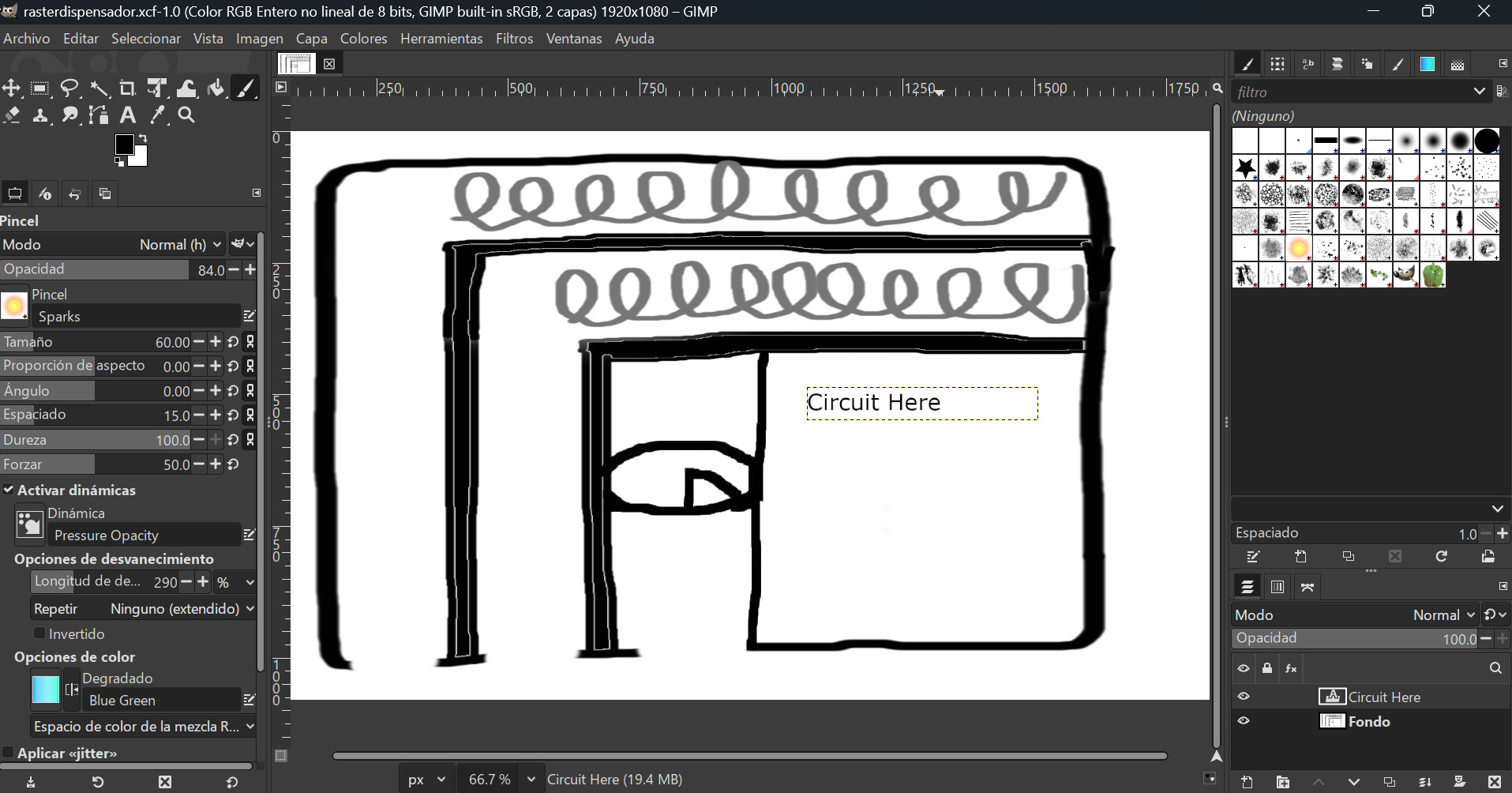
I started by drawing the inner part of my dispenser, specifically the container area, because this is the component that gives life and functionality to the entire machine. At this stage, I focused on defining how the internal spaces would work and interact. I experimented with the different brushes available in GIMP and explored several tools, such as the bucket fill tool, which allowed me to color closed shapes easily, as well as text boxes and other drawing options. This experimentation helped me better visualize the internal structure and refine my initial idea.
Vector graphics use mathematical definitions of lines and geometric shapes, so they can be resized without losing quality. Unlike raster images, which are made of pixels, vector design is based on precise paths, constraints, and dimensions. This makes it ideal for laser cutting, CNC, and digital fabrication. Inkscape is an example of vector-based software used for 2D design.
Inkscape Essential Tools
To move, scale, and rotate objects.
For precise editing of paths and curves.
Including alignment, grouping, and color control.
Convert raster images into vector paths.
First Steps: Just Drawing a Character
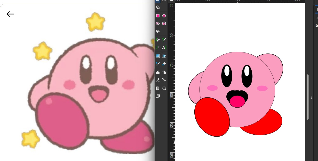
In order to practice with these new tools, I drew Kirby, one of my favorite Nintendo characters. This helped me learn how to combine basic geometric shapes and apply colors effectively.

Setting up the Workspace
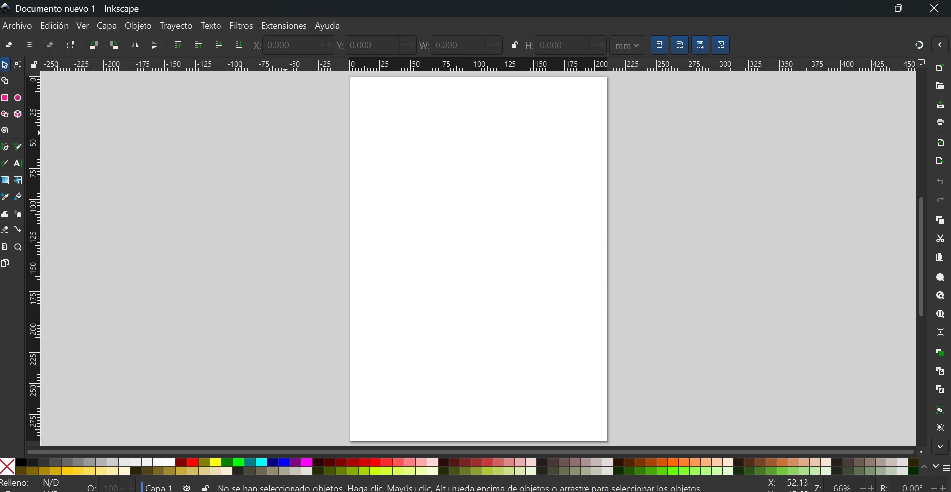
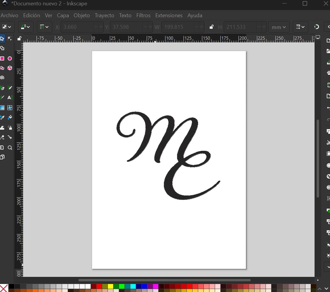
First, I created a new document in Inkscape.
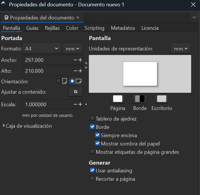
Then I adjusted the page orientation to Horizontal by going to File → Document Properties.
The Drawing Process
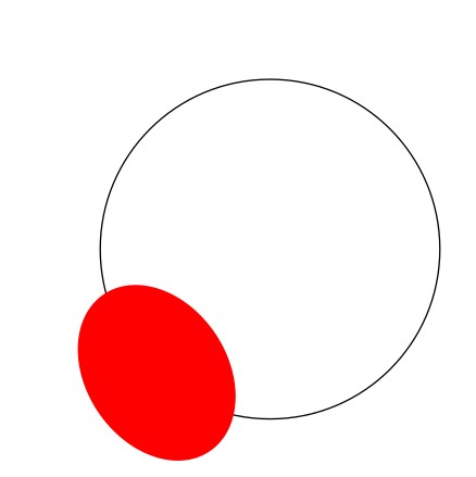
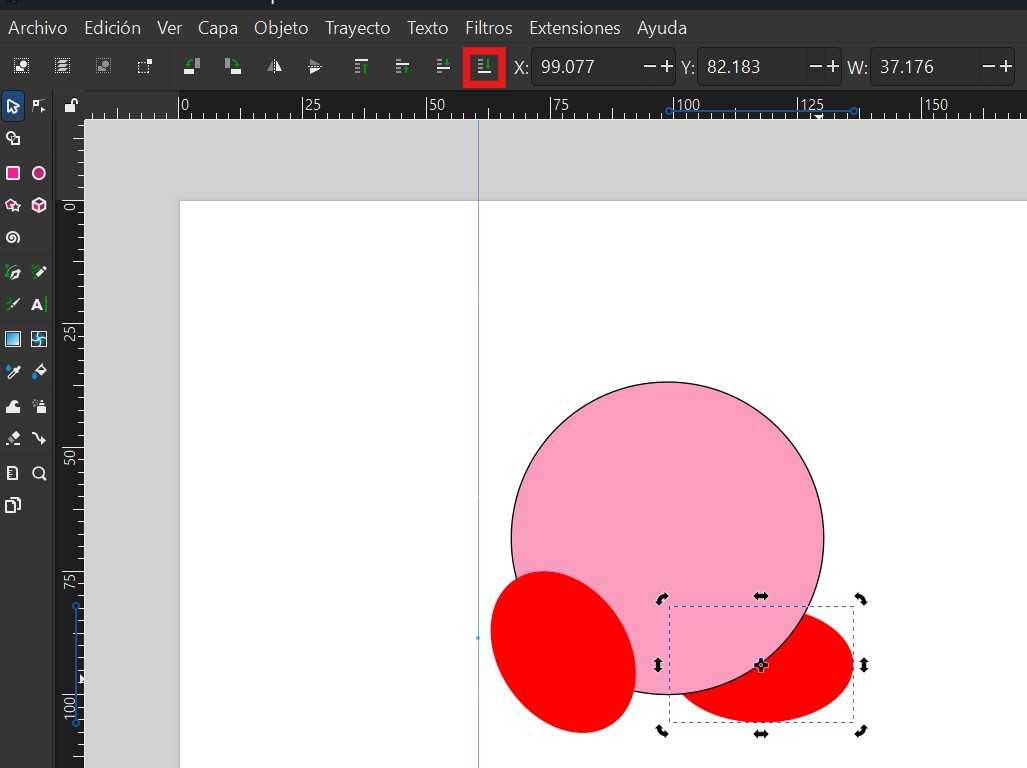
Shapes: I used circles and basic geometric tools to recreate the character's structure.
Stroke & Fill: I adjusted stroke thickness and applied solid fills to define the vector elements.
Composition: I combined multiple layers and shapes to build the final character detail by detail. The composition allowed me to control each element independently.
Here's how the Kirby design evolved throughout the drawing process:
Vectorizing an Image (Trace Bitmap)
One of the most useful features for fabrication (laser/vinyl cutting) is the Trace Bitmap tool, which converts a raster image into an editable vector. This was particularly valuable because it means I can take a sketch or photograph and automatically convert it into a cutting-ready vector file.
I imported the raster image into Inkscape (File → Import) and selected it.
I opened the tool via Path → Trace Bitmap.
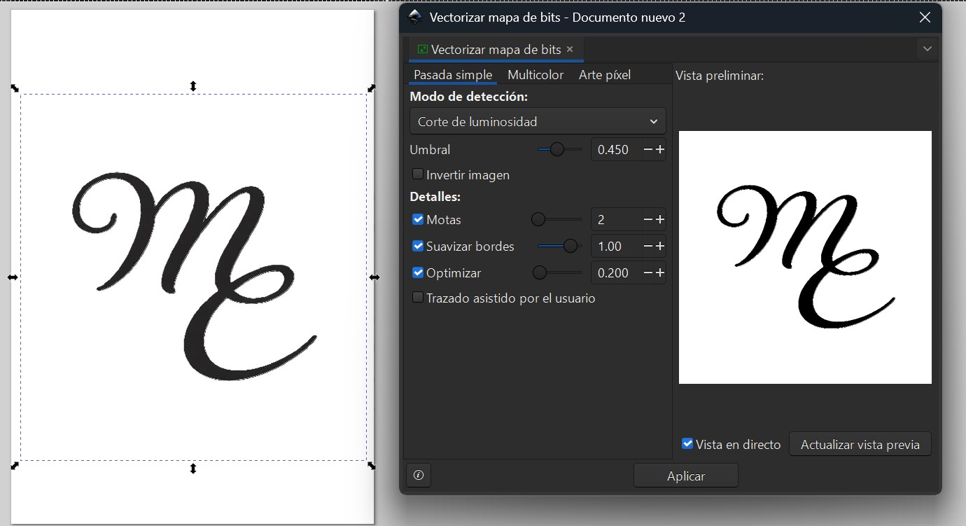
Depending on the image complexity, I used the Brightness cutoff mode within the Trace Bitmap panel to generate clean black-and-white silhouettes.
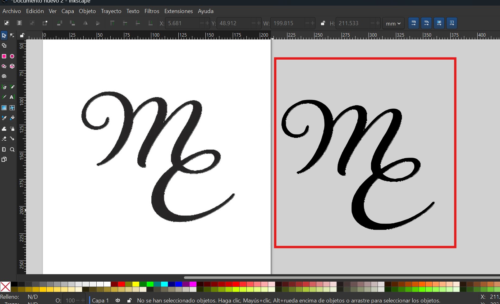
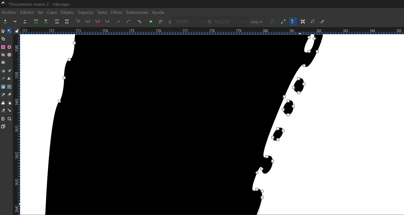
After clicking Apply, Inkscape generated a new vector path on top of the original. I moved the vector aside to compare results, deleted the raster version, and refined the nodes using the Node Tool to remove any unwanted artifacts.
3D Design
Spring Mechanism
3D design involves creating digital models with depth, enabling the visualization, simulation, and fabrication of physical objects. Various CAD platforms—such as Onshape, Fusion 360, Inventor, and SolidWorks—provide different tools and workflows depending on project needs.
Software Selection
Onshape and SolidWorks emphasize parametric flexibility, while Fusion 360 and Inventor focus on generating consistent solid models. This approach reduces fabrication errors and improves export reliability, which is why Fusion 360 and Inventor were primarily used in this project.
Project Focus: Spring Mechanism
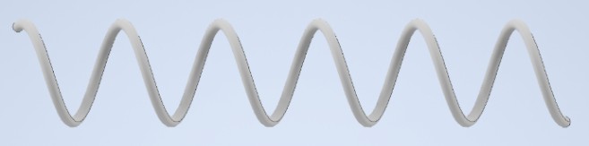
The project centers on modeling a spring mechanism, the core component of the system. It is designed to dispense one product at a time while keeping items individually organized.
Measurements and Simulation
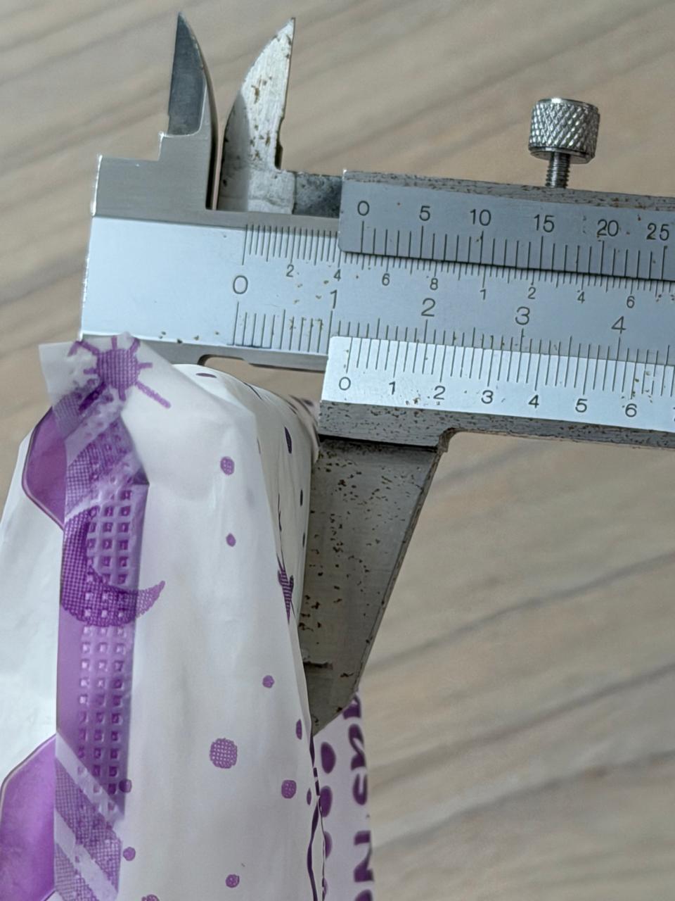
To define the mechanism's dimensions, the width of a sanitary pad was measured using a vernier caliper, resulting in an approximate value of 4.5 cm. This measurement was used to simulate the gripping mechanism and determine the spacing required for the spring system to function effectively.
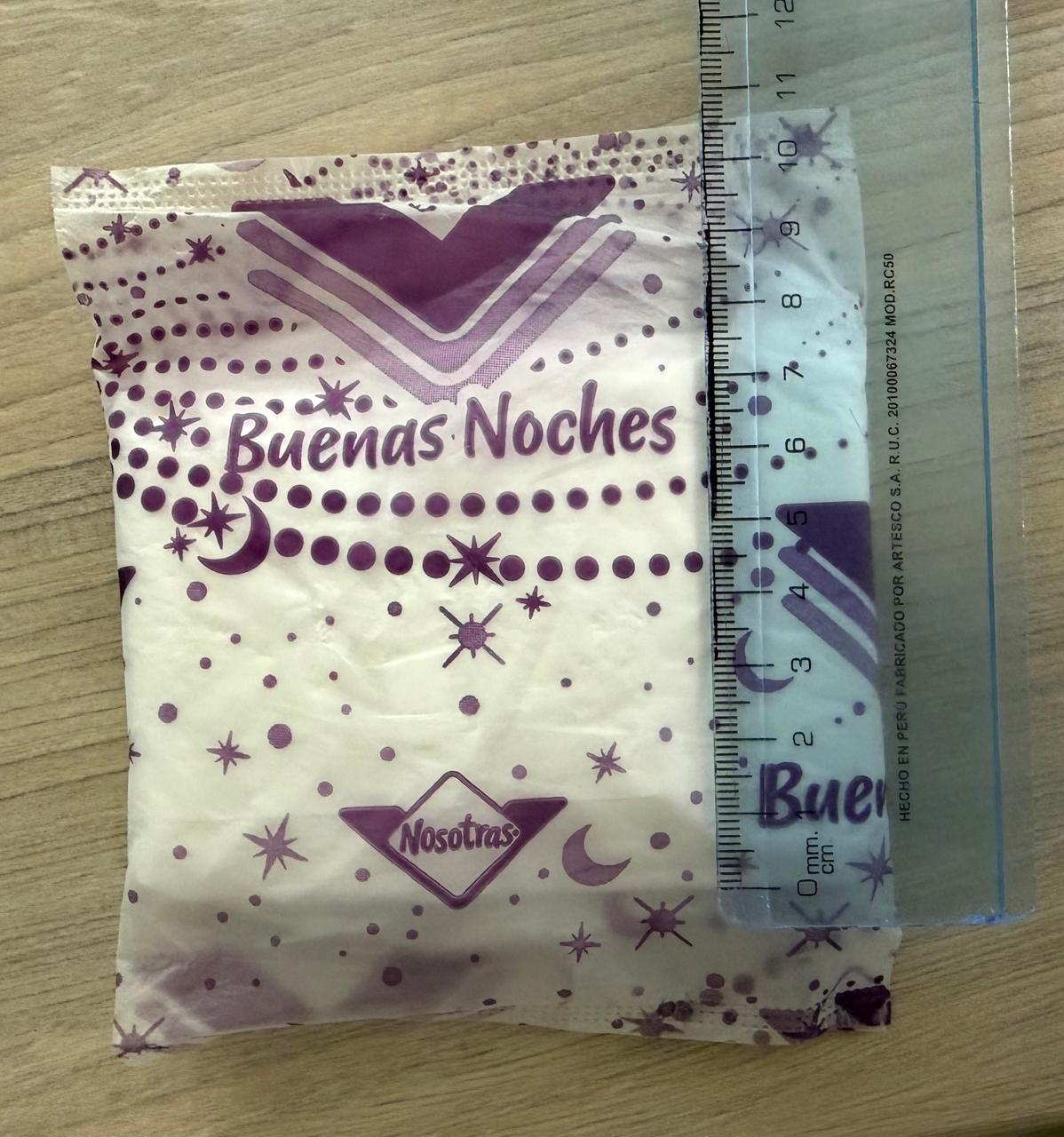
Applying the Measurements to 3D
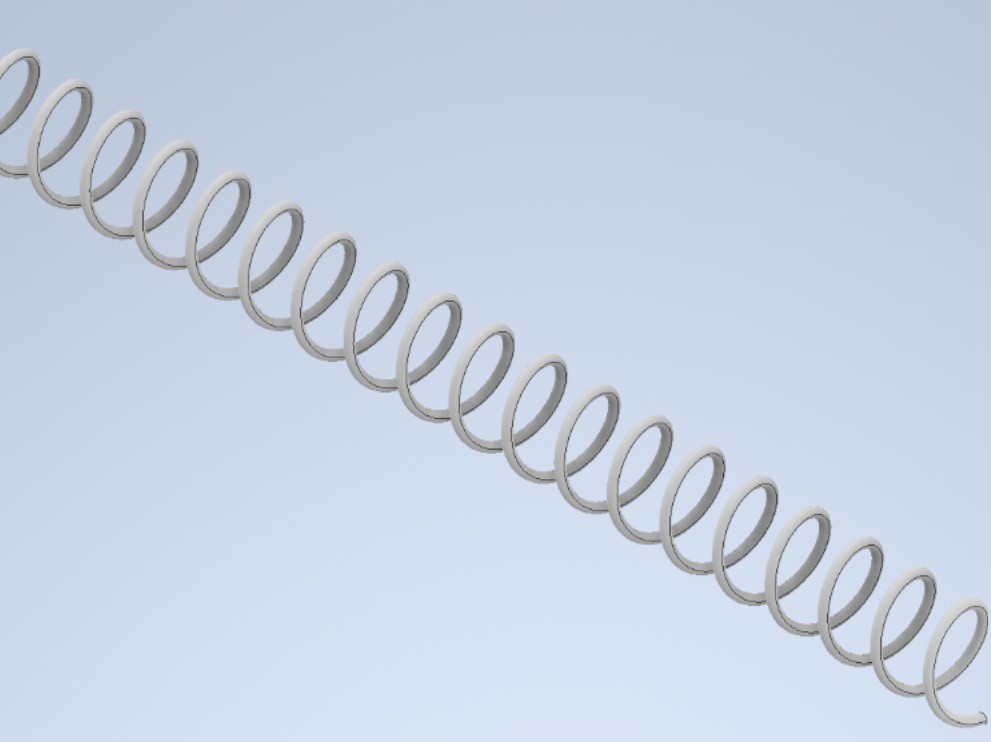
Since this spring must be suitable for properly holding sanitary pads with the measured dimensions (4.5 cm width and 9 cm height), I adjusted the parameters to create an abstract but realistic approximation of the spring I needed.
I chose the Pitch and Height method because these are the measurements available from the product: 4.5 cm (diameter) and 9 cm (height).
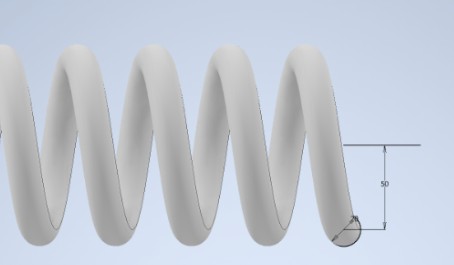
I opened Autodesk Inventor and selected the XY plane to create a new 2D sketch. I created a circle to define the wire profile and drew a horizontal line along the Y axis to serve as the reference axis. Using the Dimension tool, I set the circle diameter to 5 mm (spring wire thickness) and the distance between the line and circle center to 45 mm.
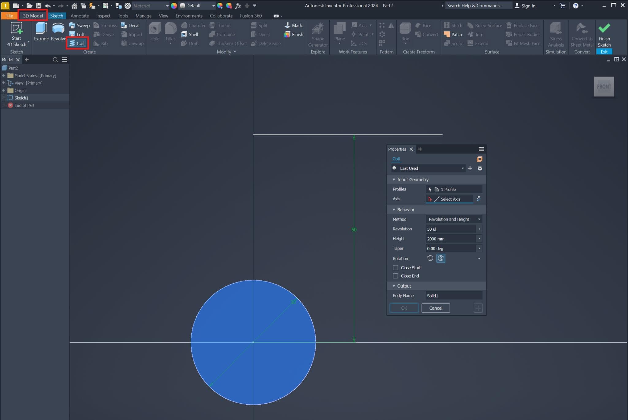
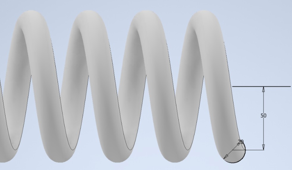
Next, I went to 3D Model → Coil and applied the coil parameters using the Pitch and Height method:
• Height = 500 mm
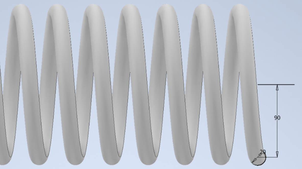
After that, I switched to the Revolution and Height method to better fit the product dimensions:
• Height: 900 mm
I pressed OK to confirm the parameters and generate the final spring model. From this experimentation, I understood a practical rule:
Height Parameter: The more the height increases, the longer the spring stretches.
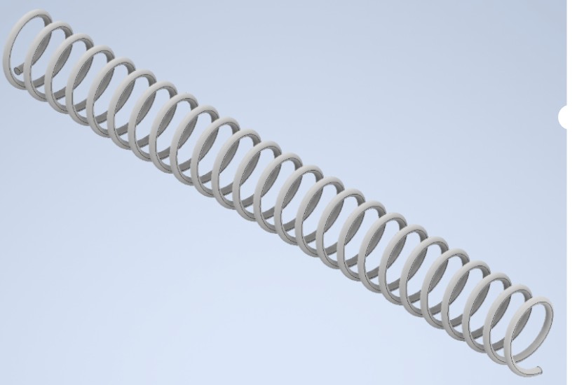
Revolution Parameter: How many cusps/turns should exist in that established range.
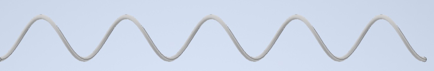
In this type of method, the third value (pitch) is calculated automatically from the parameters of revolution and height.
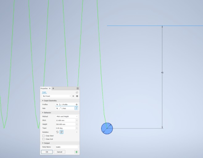
Testing the Pitch and Height Parameters
Pitch Parameter: Axial distance between two consecutive turns of the spring.
Height Parameter: This option also extends the spring length, but in this case the value that is calculated automatically is the number of revolutions.
After creating the solid, it was still possible to modify it from the initial sketch and from the solid's properties. To do this, I right-clicked on the 3D modeling feature "Coil1" in the timeline (or feature tree). This opened a menu with several options:
"Edit Feature" takes you back to the 3D solid properties window, where you can adjust parameters such as pitch, height, or number of revolutions.
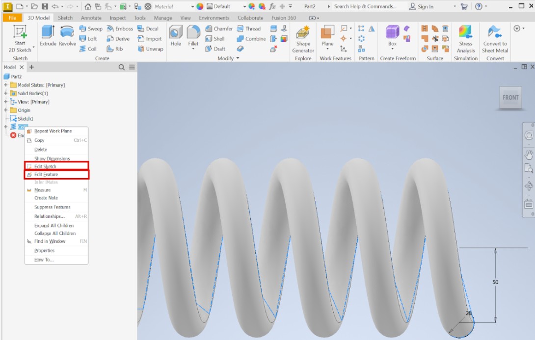
Taking advantage of the Edit Sketch option, I can explain the relationship between the circle radius and the distance between the circle radius and the reference line. These two parameters work together to define the overall diameter and the wire thickness of the spring. The circle radius mainly controls the size of the coil, while the distance to the line influences how thick the spring wire becomes in the final geometry.
At this stage, it is important to understand that both values are interdependent, since changing one will affect the proportions of the spring.
Testing Wire Diameter Changes
First, by changing the circle diameter, I observed that the larger the diameter is, the thicker the spring becomes, and vice versa. This happens because the spring wire is generated by extending the profile from the shape I created in the sketch.
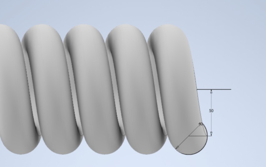
Testing Coil Diameter Changes
Now, regarding the distance between the line and the circle, by adjusting the dimensions I verified that the greater the distance between these two components, the radius of the resulting circumference becomes larger.
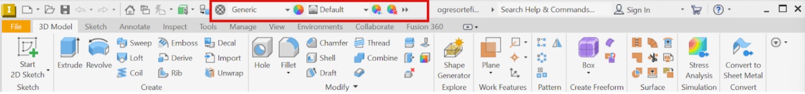
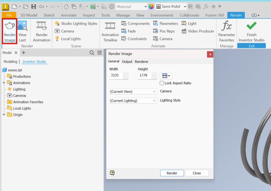
The Render function in Autodesk Inventor is used to give the model a realistic appearance by applying materials and visual properties, without changing its geometry.
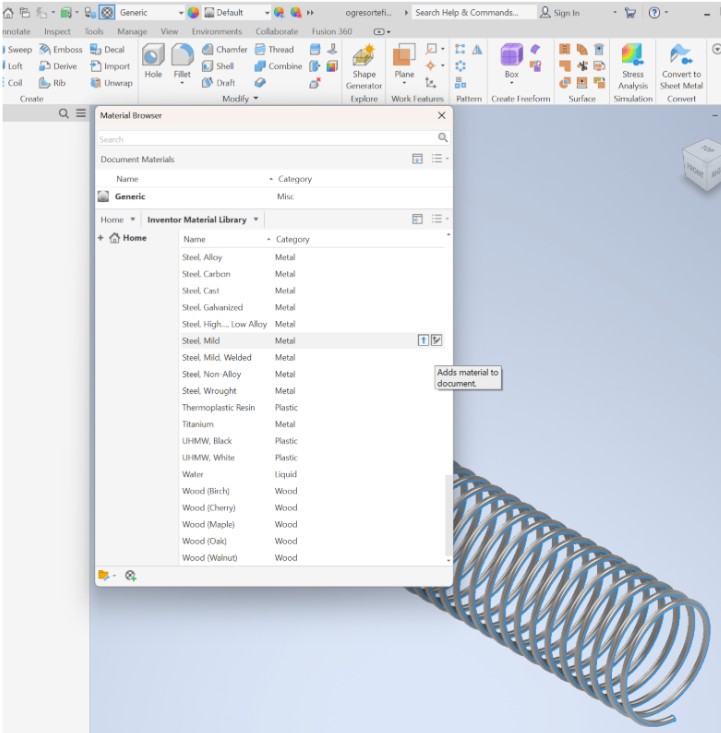
To assign a material to my design, I went to the upper right panel and clicked on the material browser icon (the white circle with small squares). From the available materials, I selected Mild Steel, which assigns metal properties such as appearance, density, and physical behavior to the model.
Setting Up Lighting
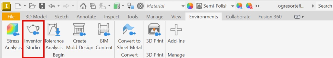
To achieve a good presentation of the material, it is necessary to choose proper lighting, as it complements the selected material and enhances its appearance. To adjust the lighting, I went to Environment → Inventor Studio and selected a preset lighting environment, such as Soft Light, to improve the visual quality of the model.
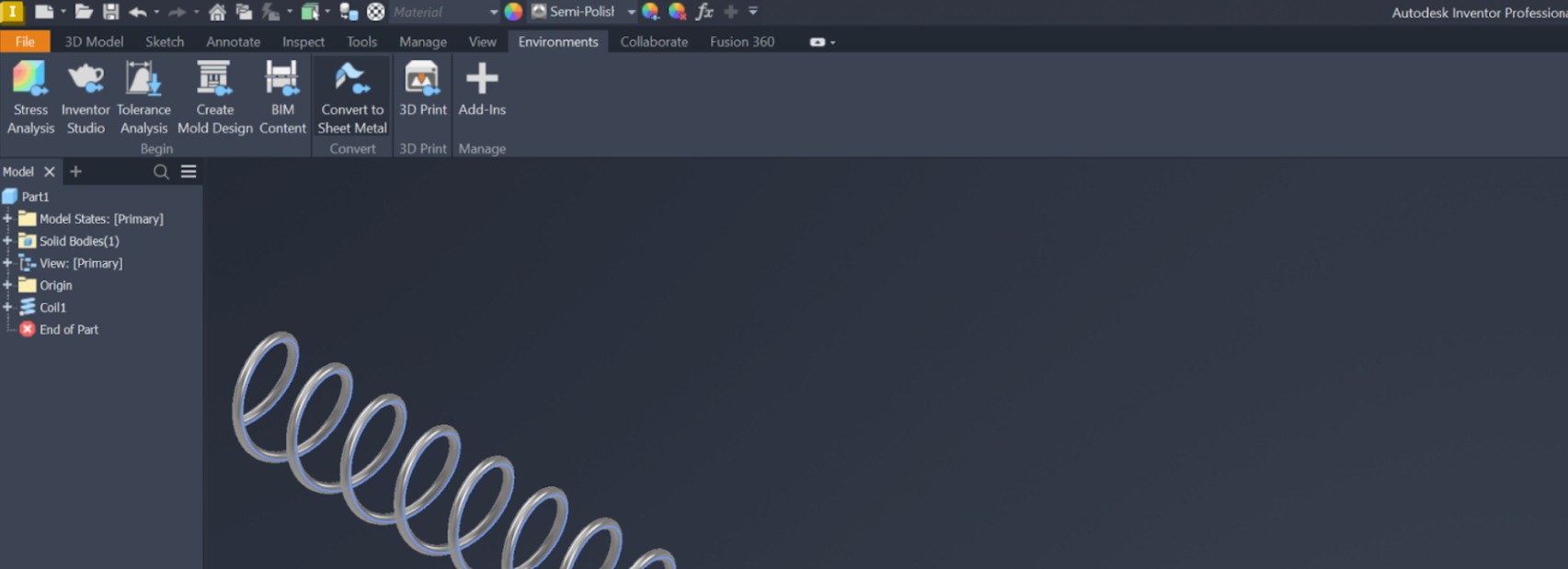
Then, I went to Studio Light Styles and selected a predefined lighting setup.
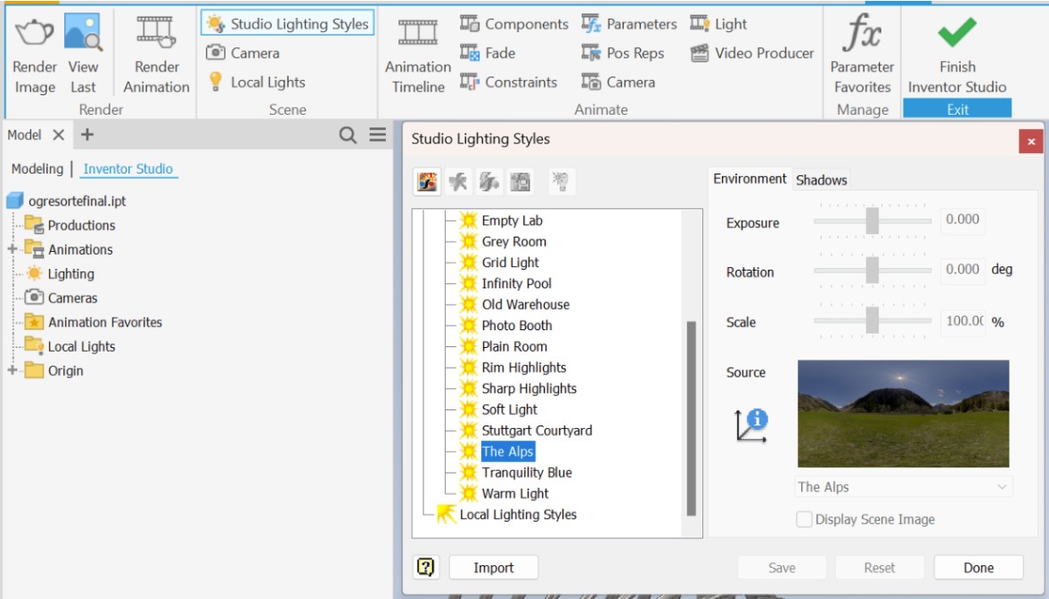
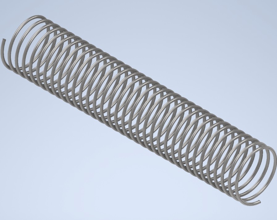
You can choose from different presets. In this case, I selected "Alps" and "Dome" to create dynamic reflections on the spring's curved surface. After that, I clicked on Render Image, adjusted the settings as needed, and generated the final rendered result.
Physical Properties Analysis
Finally, I discovered that by using the Search Help & Command and entering iProperties → Physical, it is possible to view the physical properties of the selected material. In this section, parameters such as mass, density, volume, and center of gravity are displayed, based on the material assigned to the model.
Finally, I obtained a more complete result with lighting and physical material properties applied. These details help make the model look more realistic and make it easier to understand how the spring would function before fabrication. By adding materials, colors, and lighting, the final design can be visualized more clearly.
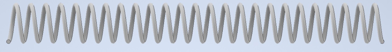
To design a spring optimized for securely holding sanitary pads, the structural dimensions were tailored around the physical properties of the product. For a functional approximation, an outer diameter of 45 mm and a rigid wire thickness were established—dimensions calculated to accommodate a stacked queue of units.
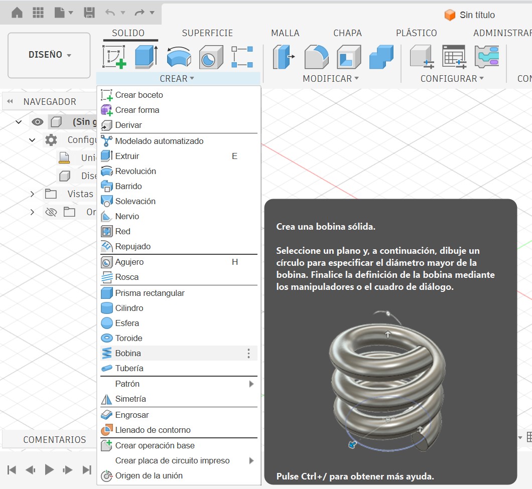
Instead of constructing a tedious manual helical sweep path using 2D profiles and separate rotational centerlines, I utilized the native Coil feature within Autodesk Fusion 360's Design workspace. This tool streamlines the process by consolidating all geometric variables into a single operation panel.
1. Setting Up the Core Parameters
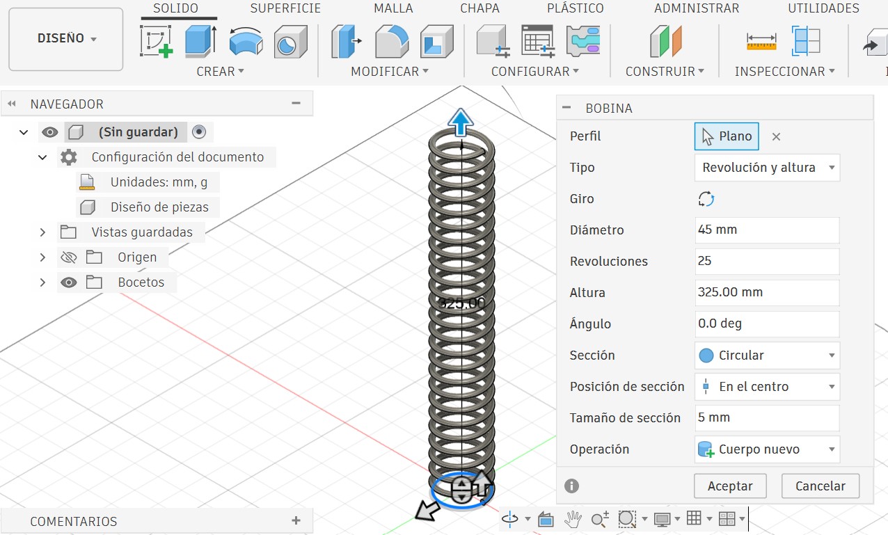
As shown in the application interface, the tool is activated by navigating to the upper bar under Create → Coil. Once the tool was active, the primary geometric values were entered directly into the parameter dialog box:
• Diameter: 45 mm (to define the outer width of the spring)
• Section Size: 5 mm with Circular section at Center (for rigid structural profile)
• Revolutions: 25 (distributed over height)
• Height: 325.00 mm (stretches the component to leave clean, even gaps between each turn)
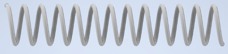
2. In-Canvas Controls & Dynamic Dimension Testing
A major workflow benefit in Fusion 360 is the presence of dynamic push-arrows (manipulators) right inside the workspace canvas. These graphic arrows allow you to visually pull, stretch, or compress the height and diameter properties on the fly before committing to the final values in the dialogue box.
Under this specific pairing method, the third parameter (Pitch) is automatically calculated by the software as a dependent value based on the exact 325.00 mm height and 25 turns input.
3. Modifying the Feature History
Once the 3D solid is generated, Fusion 360 logs the operation chronologically in the parametric timeline bar located at the bottom of the interface. If subsequent adjustments are needed on the geometry, you can simply right-click the Coil icon inside the timeline and select Edit Feature. This reopens the property parameters, allowing quick updates to the diameter, pitch, or revolutions without breaking downstream model references.
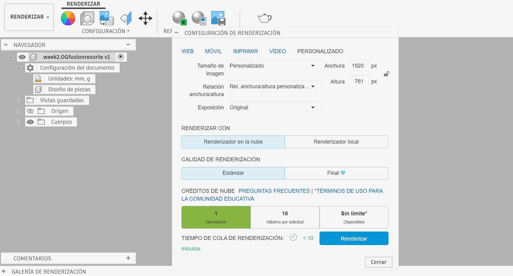
4. Rendering and Material Selection
To give the component a realistic physical appearance without changing its underlying geometry, I switched from the Design workspace over to the Render workspace using the navigation menu.
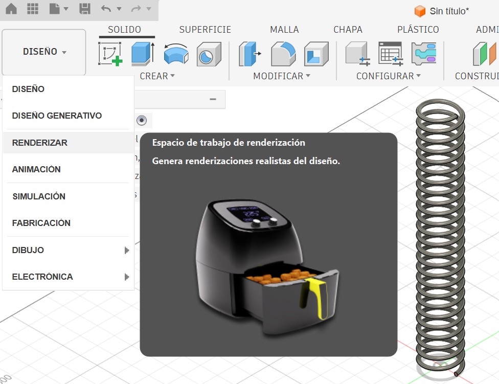
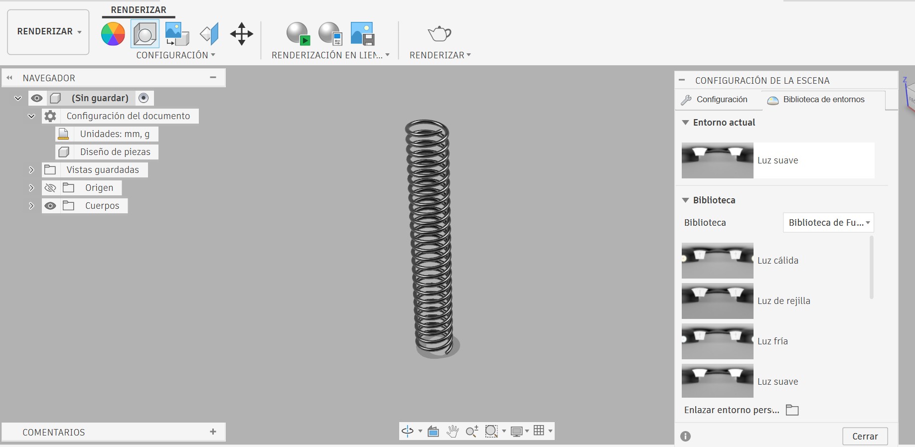
Scene Settings & Studio Lighting
To emphasize the lighting highlights along the curved surface of the steel wire, I opened Setup → Scene Settings (Shortcut: Shift + F). Inside the Environment Library tab, I tried different predefined lighting setups to bounce light evenly across the geometric curves of the coils.
Inventor vs. Fusion 360 — Feature Comparison
| Feature | Autodesk Inventor | Autodesk Fusion 360 |
|---|---|---|
| Design Approach | Based on structural relationships and strict geometric constraints. | Based on direct, intuitive, and agile modeling directly on the canvas. |
| Sketch Requirement | Mandatory. It requires drawing the cross-sectional profile (circle) and a separate construction line acting as the axis of revolution. | Not required. It is generated directly by selecting a base plane, an origin point, and an overall diameter input. |
| Diameter Control | Analytically determined by the exact distance between the wire profile and the axis line within the 2D sketch plane. | Configured by entering a direct numerical value in the properties panel or by pulling the in-canvas handles. |
| Real-Time Control | Changes must be made by editing the dimensions of the base sketch to recalculate the solid proportions. | Offers interactive on-screen push-arrows (manipulators) to stretch or compress the spring dynamically. |
| Environment Workspace | Structured into separate, independent technical sub-menus (iProperties, Inventor Studio). | Fluidly integrated into clear environmental tabs (Design, Render). |
| Learning Curve | Highly technical, rigorous, and explicitly oriented toward detailed engineering. | Accessible, visual, and user-friendly for rapid prototyping workflows. |
Image & Video
Compression
During this week's class, the global instructors emphasized the importance of compressing images and videos for web publication, since this assignment includes a large amount of media content.
I used Squoosh for image compression and VideoCompress.ai for video optimization to ensure fast loading times across all media formats.
A web-based image compression tool used to optimize images for the web. It is fast, free, and works directly in the browser without requiring installation.
A free online video compression tool that allows you to choose the output file size and compress videos instantly without limits.
Image Compression - Squoosh
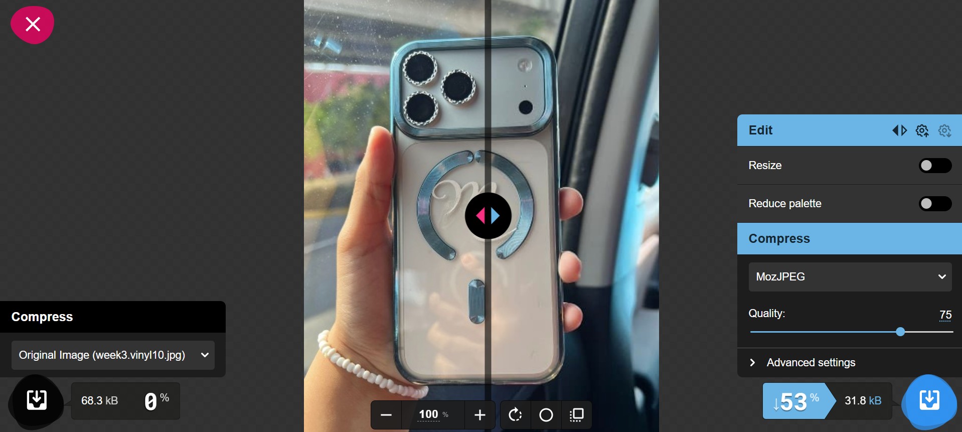
Squoosh (https://squoosh.app/) is a free web-based tool used to compress and optimize images for websites. It works directly in the browser and does not require installation.

I used Squoosh to reduce the size of my images and improve my website loading speed. It also allows images to be converted to formats such as WebP. For example, some images were reduced from around 3 MB to 400 KB, keeping good visual quality.
The process is simple: first, I uploaded the image to Squoosh. After a few seconds, the tool showed the original and compressed versions, including the new file size and compression percentage. Then, I adjusted the quality if needed and downloaded the optimized image.
Video Compression — VideoCompress.ai
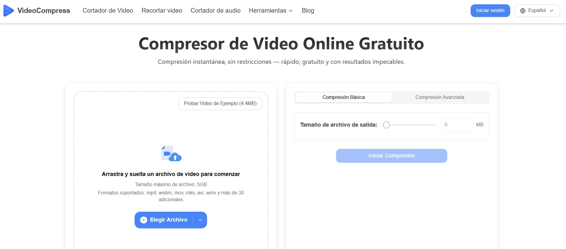
For video compression, I used VideoCompress.ai (https://videocompress.ai/es), a completely free online tool that allows instant video compression without any file size restrictions. This tool was essential for optimizing the videos I captured during fabrication and testing for web publication.
Why VideoCompress.ai?
VideoCompress.ai stands out because it offers several key advantages:
You can specify the exact file size you want for the compressed video. This gives complete control over the final result.
No watermarks, no time limits, no restrictions. Everything is free and available immediately in your browser.
Videos are compressed instantly without needing to create an account or wait for cloud processing queues.
Despite significant file size reduction, the video quality remains clear and suitable for web publication.
How I Used VideoCompress.ai
The process was straightforward and efficient:
I accessed VideoCompress.ai and uploaded the original video file. The tool accepted various formats including MP4, MOV, AVI, and more.
I specified the desired output file size using the slider or by entering a specific value in MB. This allowed me to balance quality and loading speed based on my website's needs.
After clicking the compression button, the tool processed the video instantly. Within seconds, I could download the optimized file ready for web publication.
Design Files
Available for Download
All the design files from this week are available for download below. These include source files from GIMP and Inkscape for 2D designs, as well as both Inventor and Fusion 360 models for the 3D spring mechanism.
📥 Week 2 — Computer-Aided Design
- GIMP Source File - models/week2.rasterdispensador.xcf
- Inkscape File Drawing - models/week2kirby.svg
- Inkscape File Vectorize - models/week2.innkscapeog.svg
- Inventor Coil - models/week2.resortefinal.ipt
- Fusion 360 Coil - models/week2.fusionresorte.stl