What is 3D Printing?
3D printing is an additive manufacturing process where an object is created layer by layer from a digital model. In FDM technology, a plastic filament is melted through a heated nozzle and deposited along X and Y axes to form each layer; then the printer moves up in Z and repeats until the part is complete.
Because the part is built in layers, mechanical strength is not uniform in all directions. Within each layer (X-Y plane), the material is continuous and stronger. Between layers (Z axis), bonding occurs through thermal adhesion, which is inherently weaker.
- Parallel to the layers → stronger
- Perpendicular to the layers → weaker
Print orientation is critical — it determines how the part will resist loads in its final application.
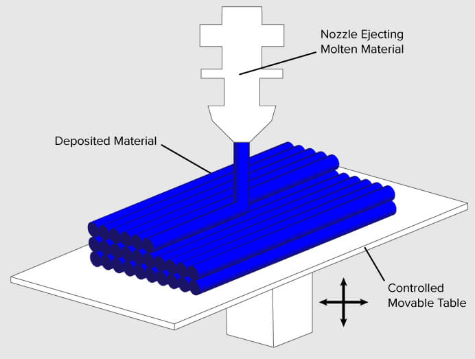
Image credit: FDM schematic by Zureks — Wikipedia / 3dprinting.com
In 3D printing, kerf refers to the amount of extra material deposited beyond the theoretical dimension of the model, due to:
- Actual extrusion width exceeding the nozzle diameter
- Thermal expansion of molten plastic during deposition
- Poorly calibrated flow rate in the slicer
- Material compression between layers
Unlike laser cutting where kerf removes material, in FDM this is excess added material: printed parts tend to come out slightly larger than modeled. Accounting for kerf is essential when designing parts that must fit together precisely.
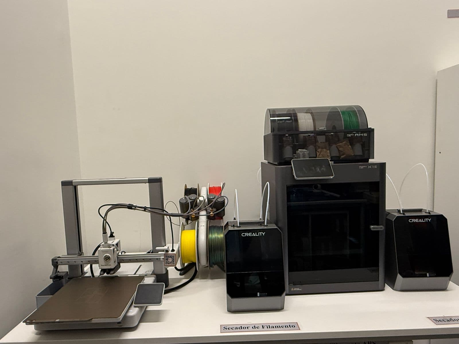
Printer Testing & Lab Equipment
For the group assignment, I worked hands-on with both the Bambu Lab X1E and the Bambu Lab A1 in the Fab Lab, comparing their performance, print quality, and suitability for components relevant to my dispenser project.
Bambu Studio
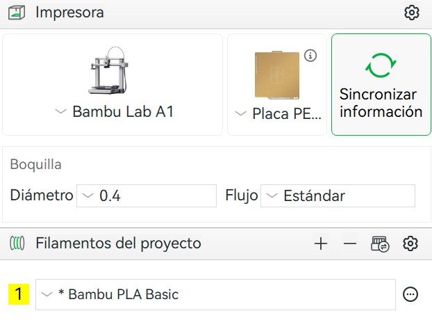
Bambu Studio is Bambu Lab's proprietary slicing software. It communicates directly with their printers over Wi-Fi, letting you send jobs, monitor print progress through the built-in camera, and manage AMS filament slots remotely — all from a single interface. Before sending anything to print, the most critical step is correctly defining the printer model, build plate type, and material, since nozzle temperature and bed adhesion settings depend entirely on the filament loaded.
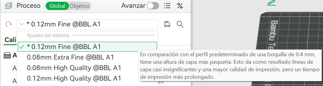
Layer Height
Smaller layers (e.g., 0.12 mm) produce a smoother surface finish at the cost of longer print times. Larger layers (e.g., 0.24 mm) print faster with less detail. The right choice depends on the purpose of the part.
Support Structures
Solid grid-based structures printed beneath overhanging surfaces. Strong and reliable, but harder to remove and leave rougher surfaces where they contact the model.
Normal supports
Branching structures that touch the model at minimum contact points. They use less material, are much easier to remove, and are ideal for organic or complex shapes.
Tree supports
The threshold angle determines when supports are generated — 45° is the standard starting point. Adding a brim (inner or outer) improves bed adhesion and prevents warping, especially with ABS.
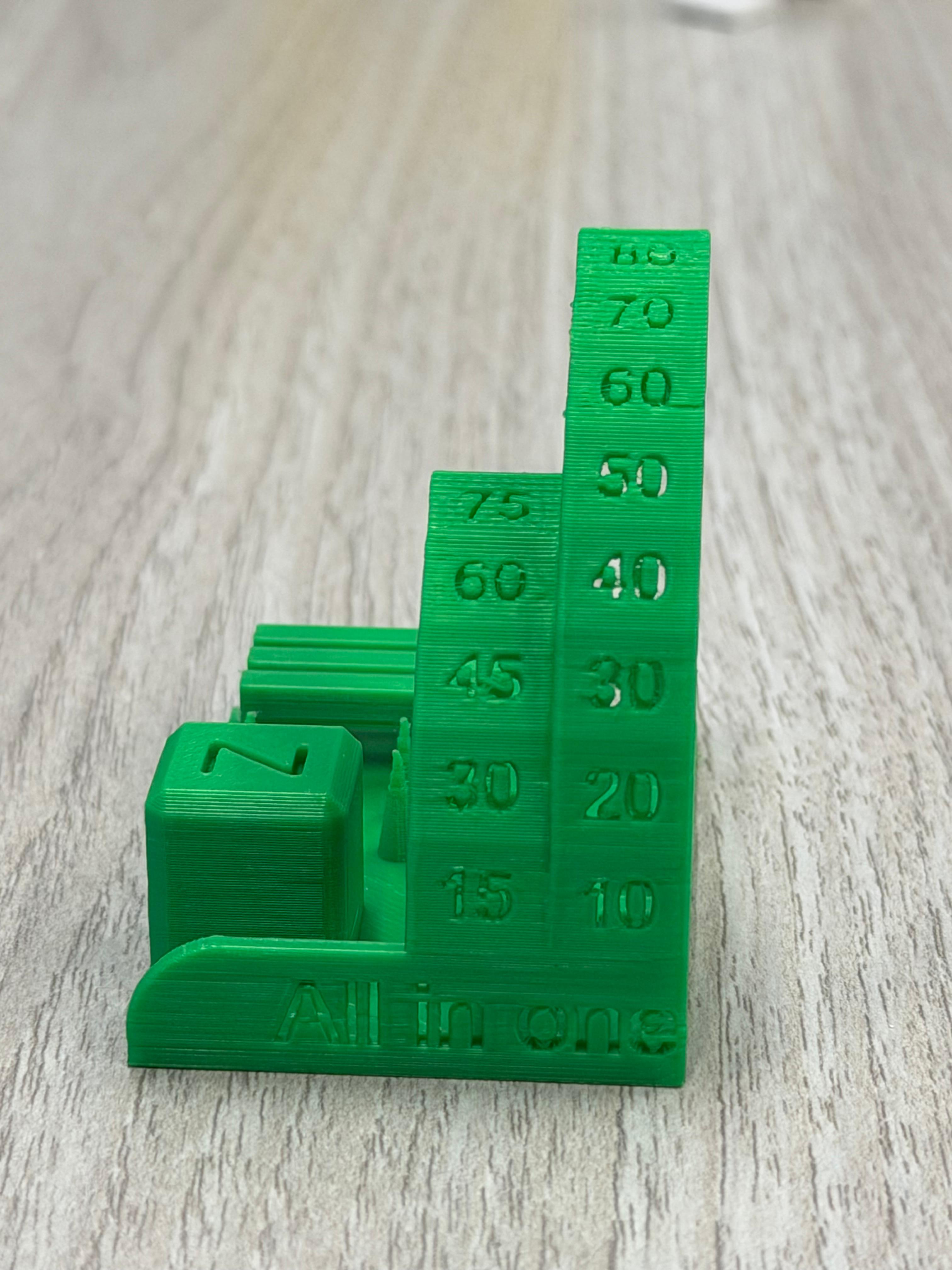
I downloaded the "Torture Test All in One" by Gmino from MakerWorld and intentionally reduced its height to see how the printer handles small, detailed geometries. The model concentrates multiple challenges in a single piece: overhang angles, thin columns, cylinders, triangular structures, engraved text, and dimensional accuracy checks.
↗ View Model on MakerWorld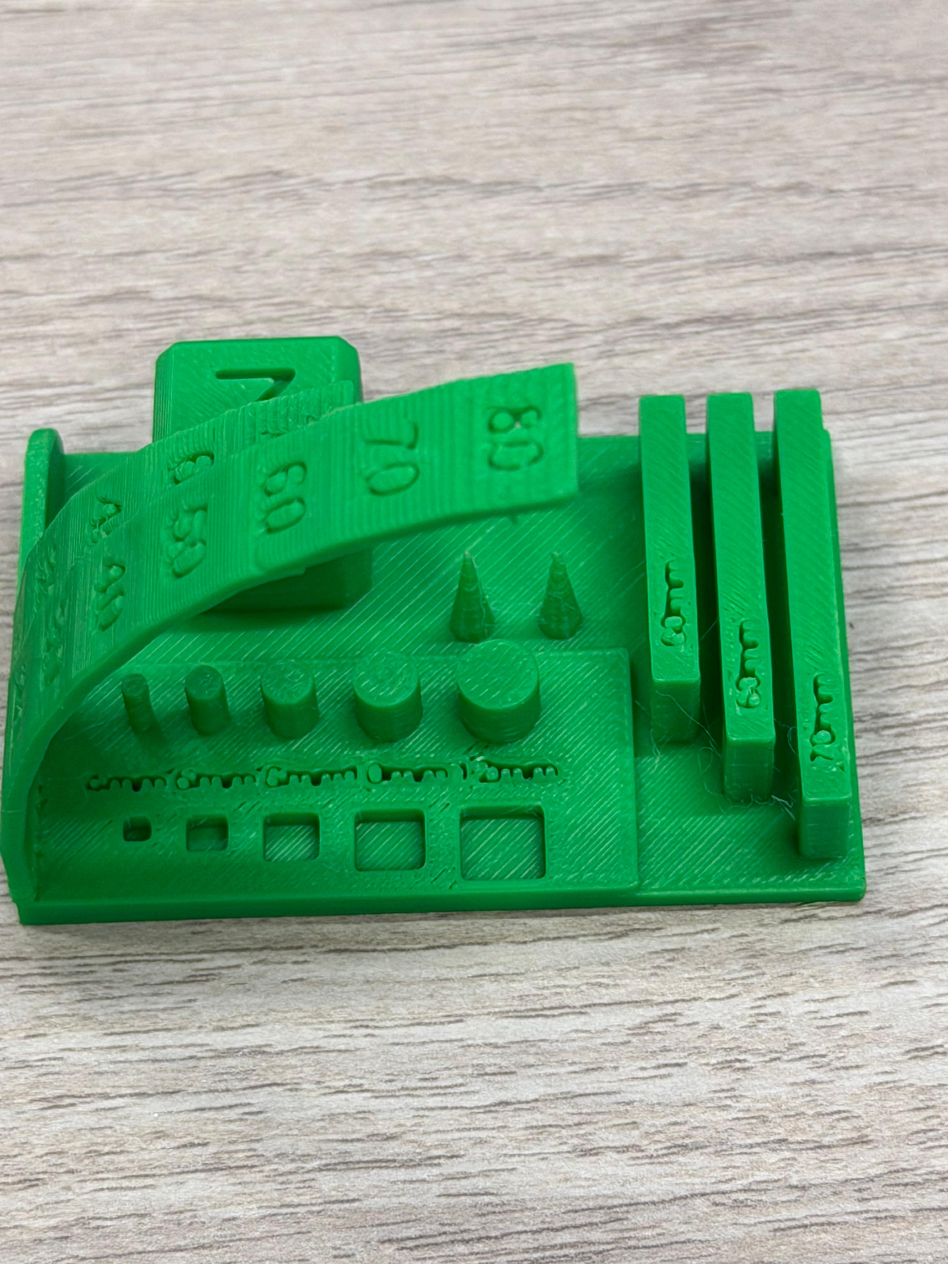
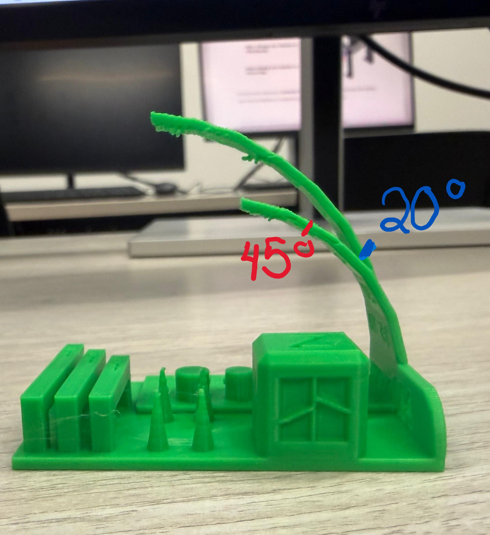
Angles above 45° begin to require support structures. Beyond this threshold, minor stringing appeared on the underside of overhangs. The 20° inclined column showed slight bending from material weight. For stable inclined structures, a taller base (over 100 mm) or reduced speed, temperature, and increased cooling would be needed.
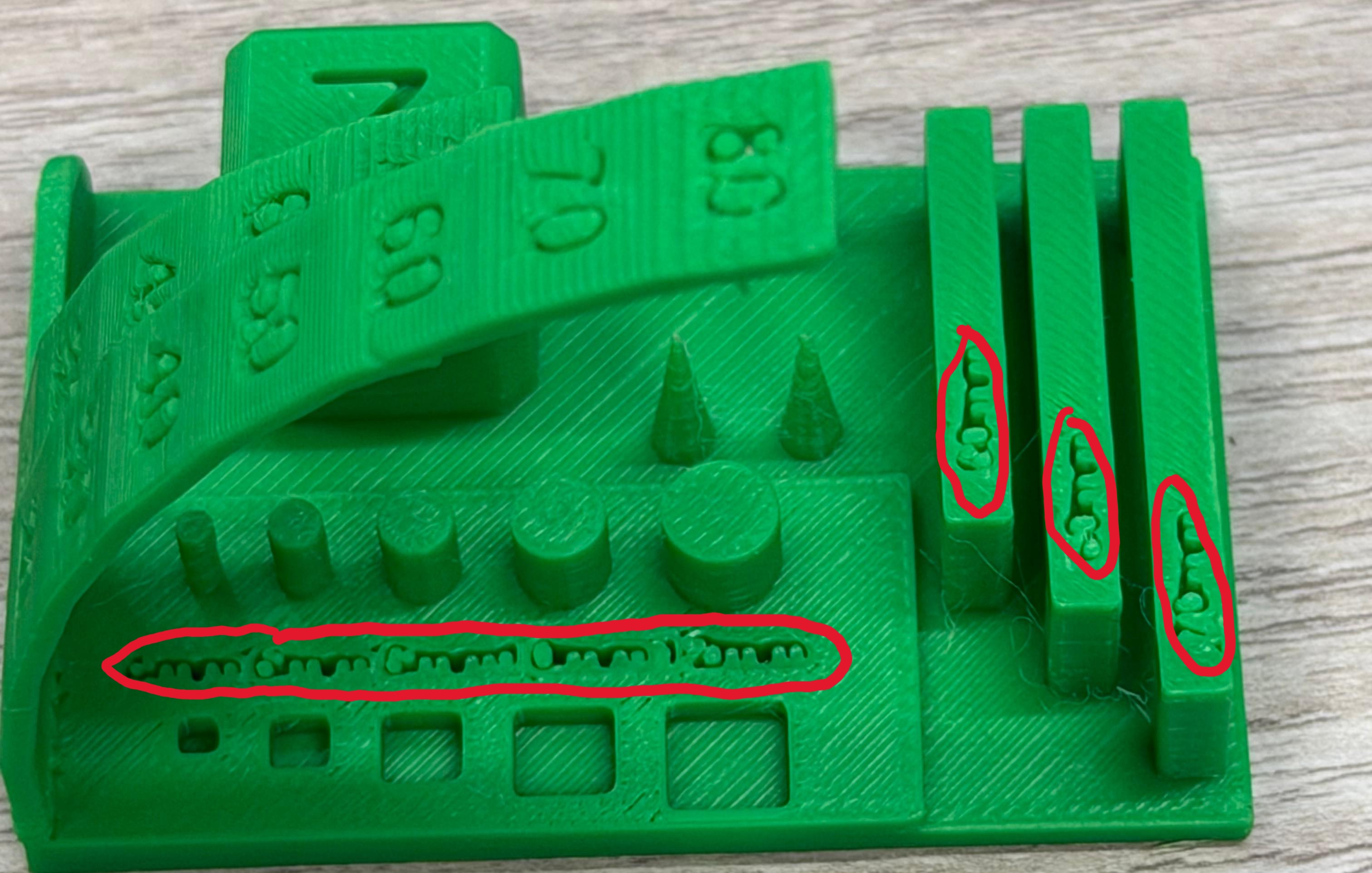
Cylinders and triangular tips showed slight deformation in the final layers, most likely from heat accumulation in small cross-sectional areas, insufficient cooling time between layers, and printing speed too high for fine details. This is common when layers deposit too quickly to solidify properly.
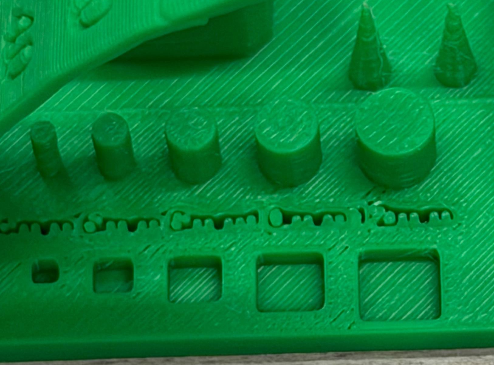
Engraved squares and numbers printed with good clarity and dimensional accuracy. However, the smallest text — bar measurement indicators at the end of the model — was not fully legible. The minimum reliable engraved text size for this configuration is approximately 4 mm.
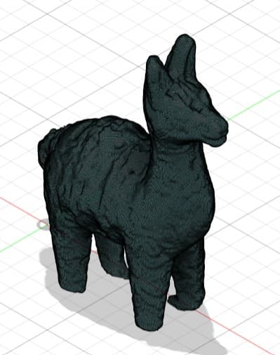
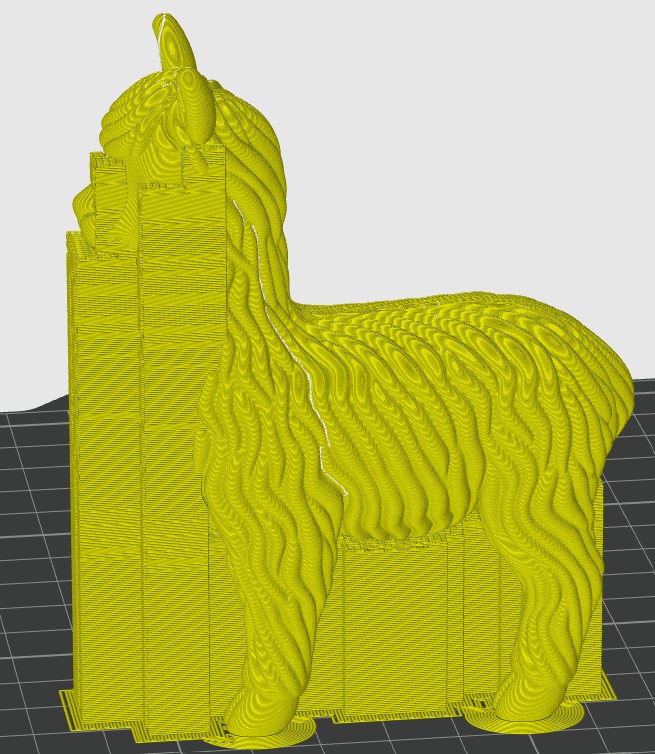
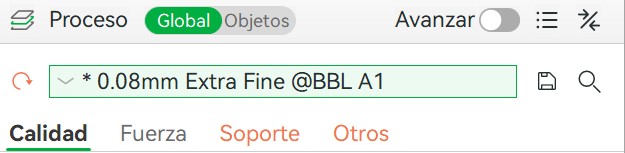
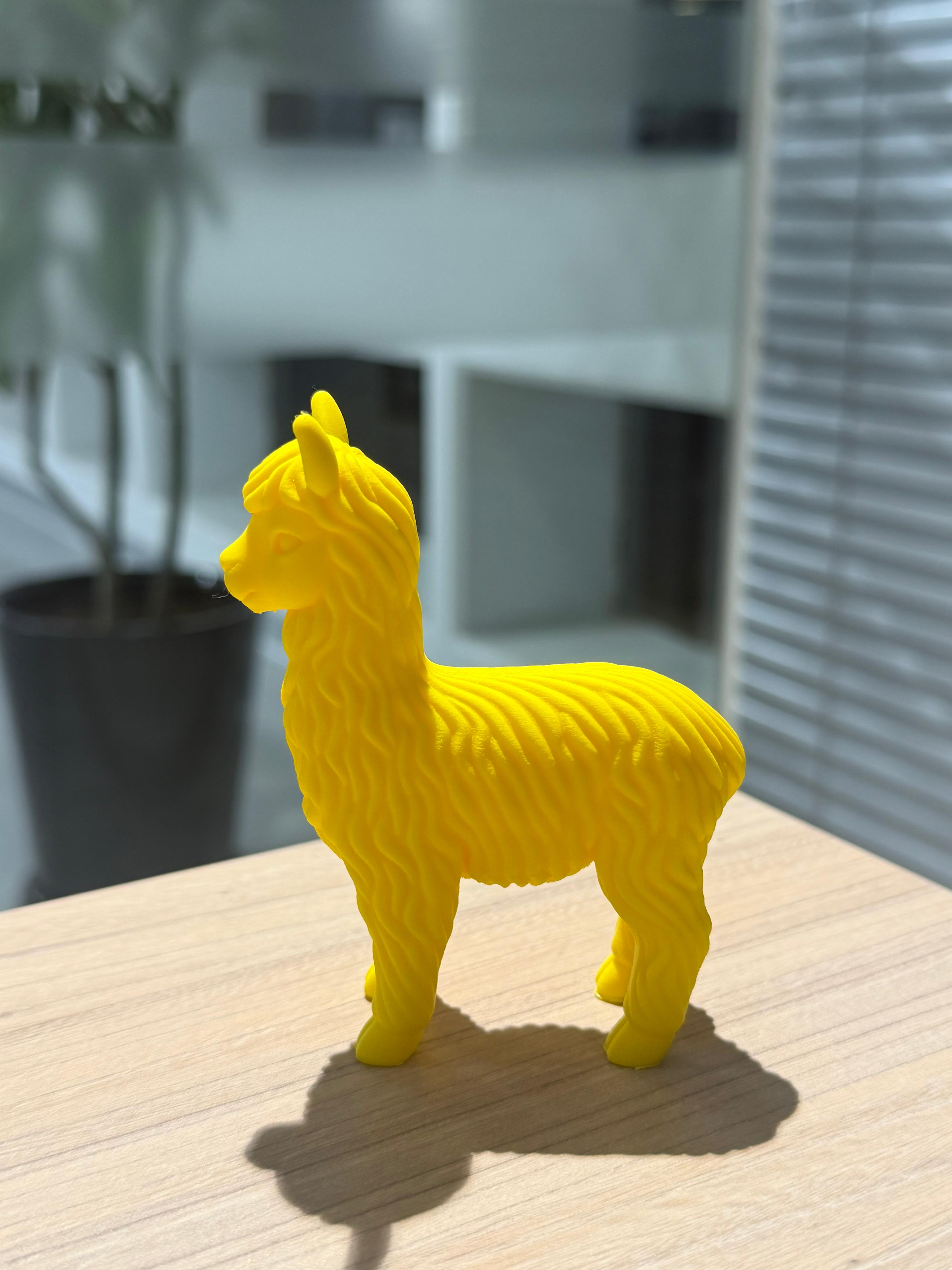
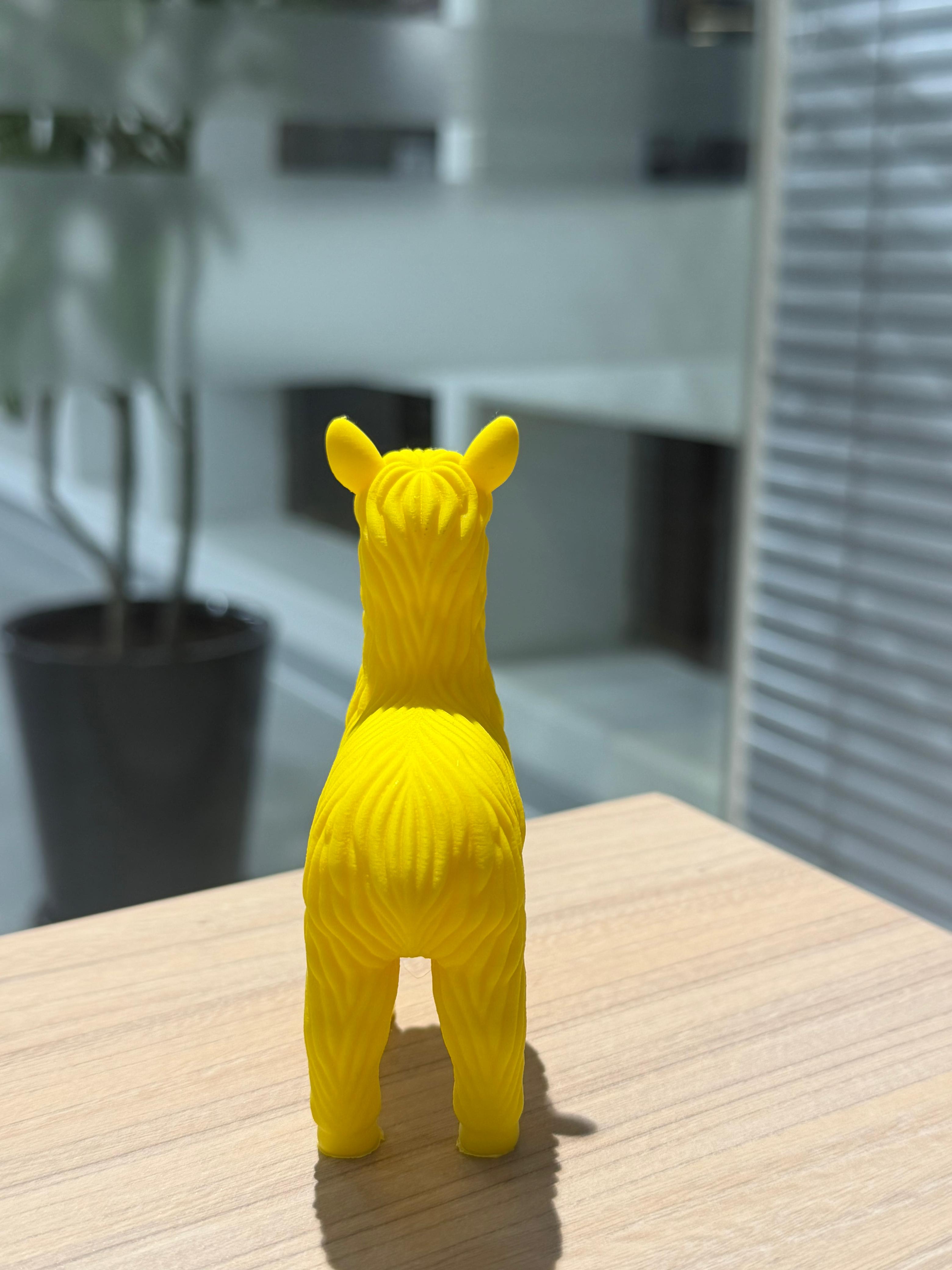
As supervisor of the Universidad del Pacífico Fab Lab, I design trophies for university events. For the first anniversary of CulturaC, the concept was a golden alpaca. Using the "Mini Alpaca" by 3DGEPRINTNL from MakerWorld was the best base to test quality before producing the final piece.
↗ View Mini Alpaca on MakerWorldLayer Height Experiment · 0.08 mm Extra Fine
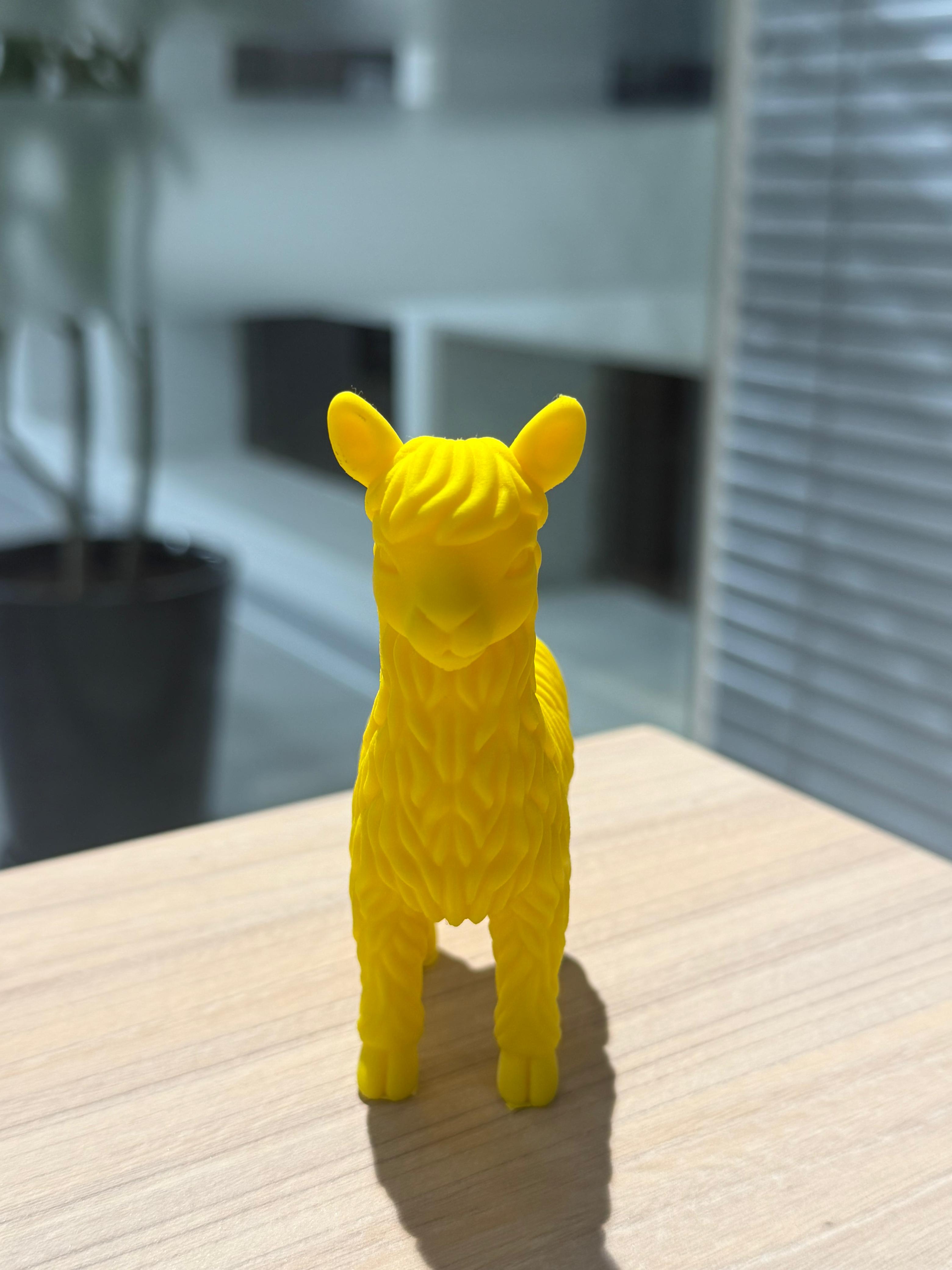
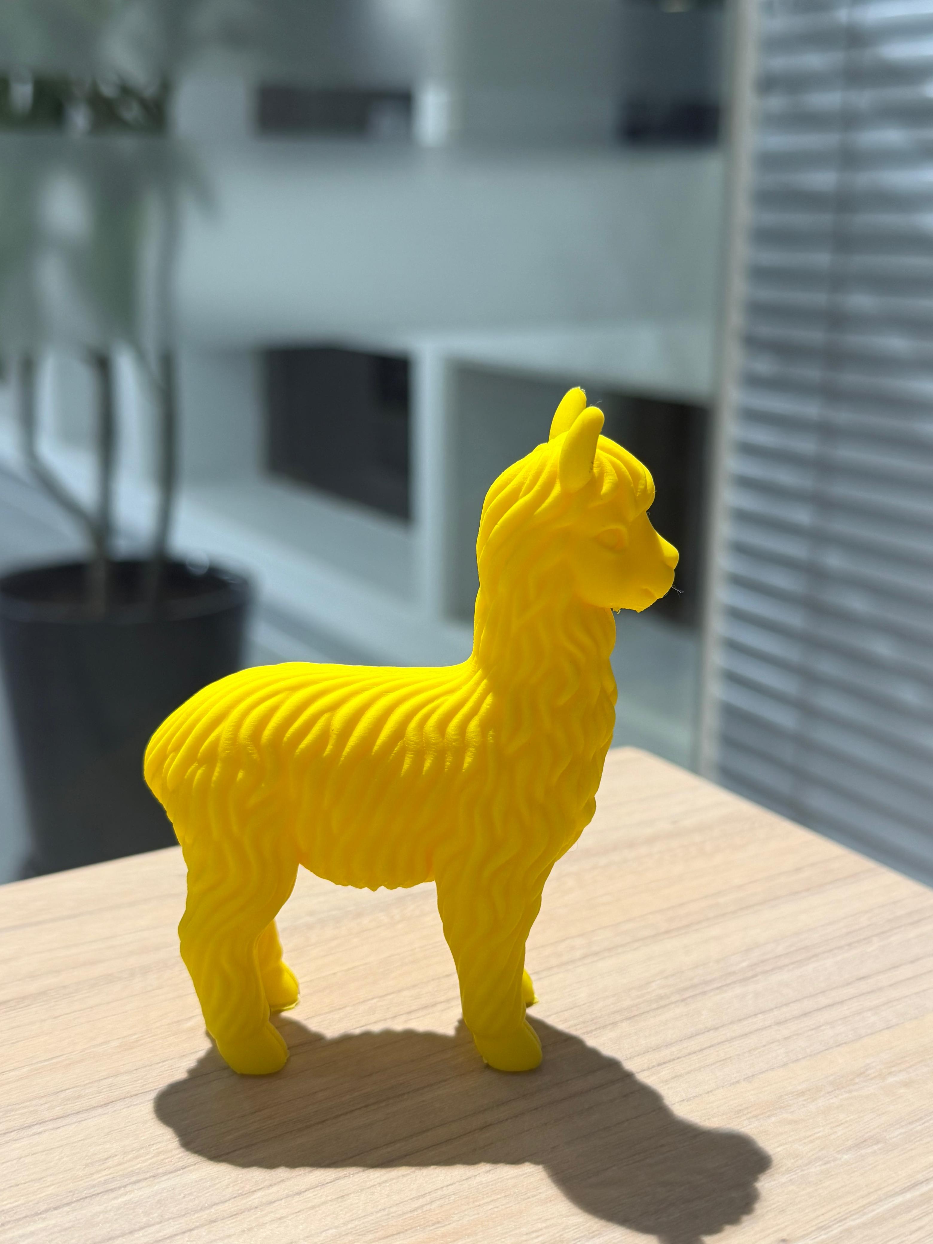
I reduced the layer height to 0.08 mm to investigate the effect on surface quality for decorative prints.
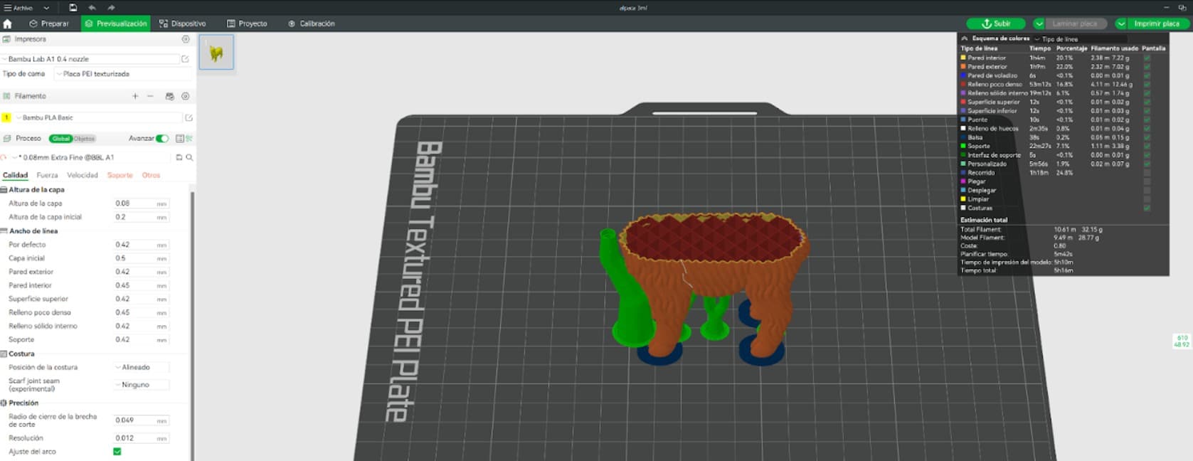
- Smoother surface transitions
- Significantly better Z resolution
- More refined organic curves
- Nearly invisible layer lines
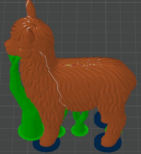
- Layer height: 0.08 mm (extra fine)
- Tree supports enabled
- Inner and outer brim
- Longer print time — result justifies it
The difference was immediately noticeable. The alpaca's organic curves appeared significantly smoother. For decorative objects, reducing the layer height improves perceived quality without any post-processing.
After running both tests alongside a lab partner, we compiled the key differences between both machines.
| Aspect | Bambu Lab X1E | Bambu Lab A1 |
|---|---|---|
| Best For | Functional parts, mechanical systems, final components | Prototypes, visual models, iterative testing |
| User Experience | More technical interface, better for experienced users | Very intuitive and beginner-friendly |
| Material Capability | Handles advanced and engineering-grade materials | Best with common materials like PLA and PETG |
| Print Stability | Very stable, ideal for long and demanding prints | Stable for regular and medium-length prints |
| Detail & Finish | Extremely clean surface and sharp details | Very good finish for standard prints |
| Learning Curve | Requires deeper understanding of settings | Easy to learn and operate quickly |
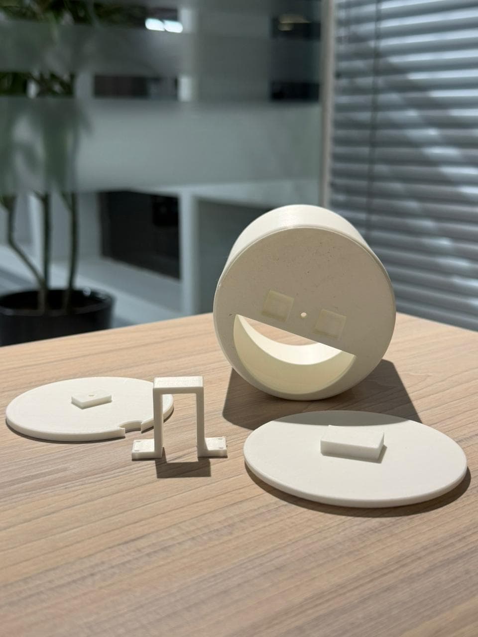
Designing & Printing the Dispenser
This week I developed a key component of my final project: The Smart Pill Dispenser. Since menstrual pain pills come in many shapes and sizes, I used a fully parametric design so the dispenser can adapt by simply changing the diameter, height, or wall thickness. I was inspired by the YouTube channel Mellow_Labs and introduced several modifications to adapt it to my project.
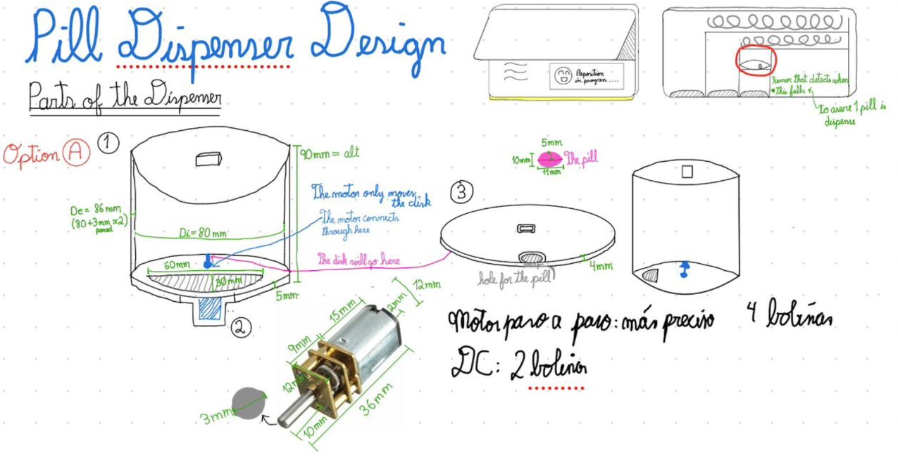
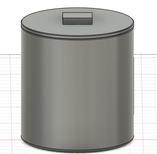
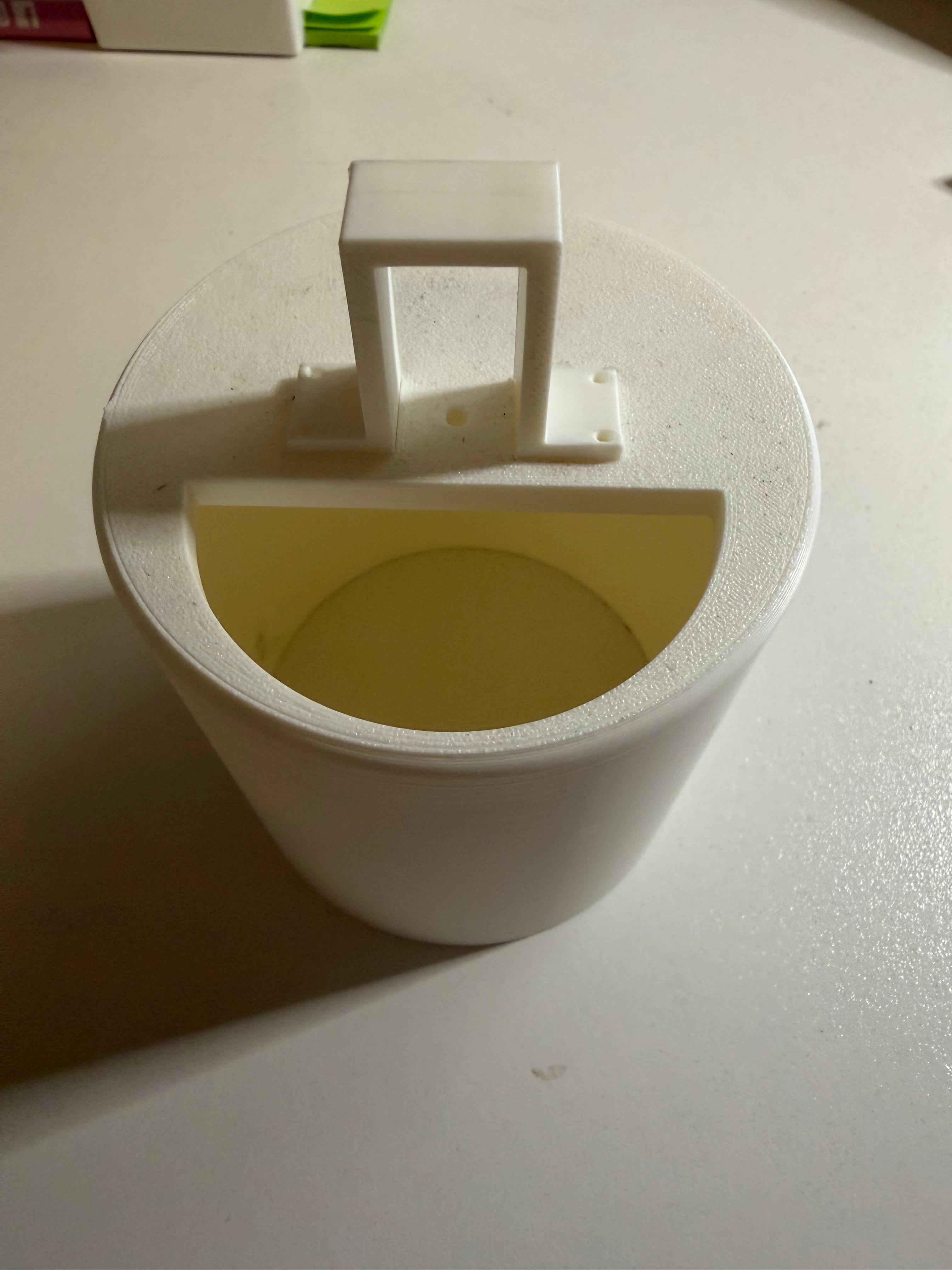
Cylindrical container with a removable lid for easy access. A rectangular opening on the top allows monitoring remaining pills and refilling the container.
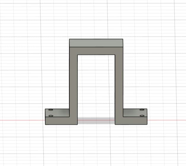
Structural component that fits into the base of the cylinder. Specifically designed to hold a 36 mm motor and ensure correct alignment with the rotary mechanism.
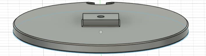
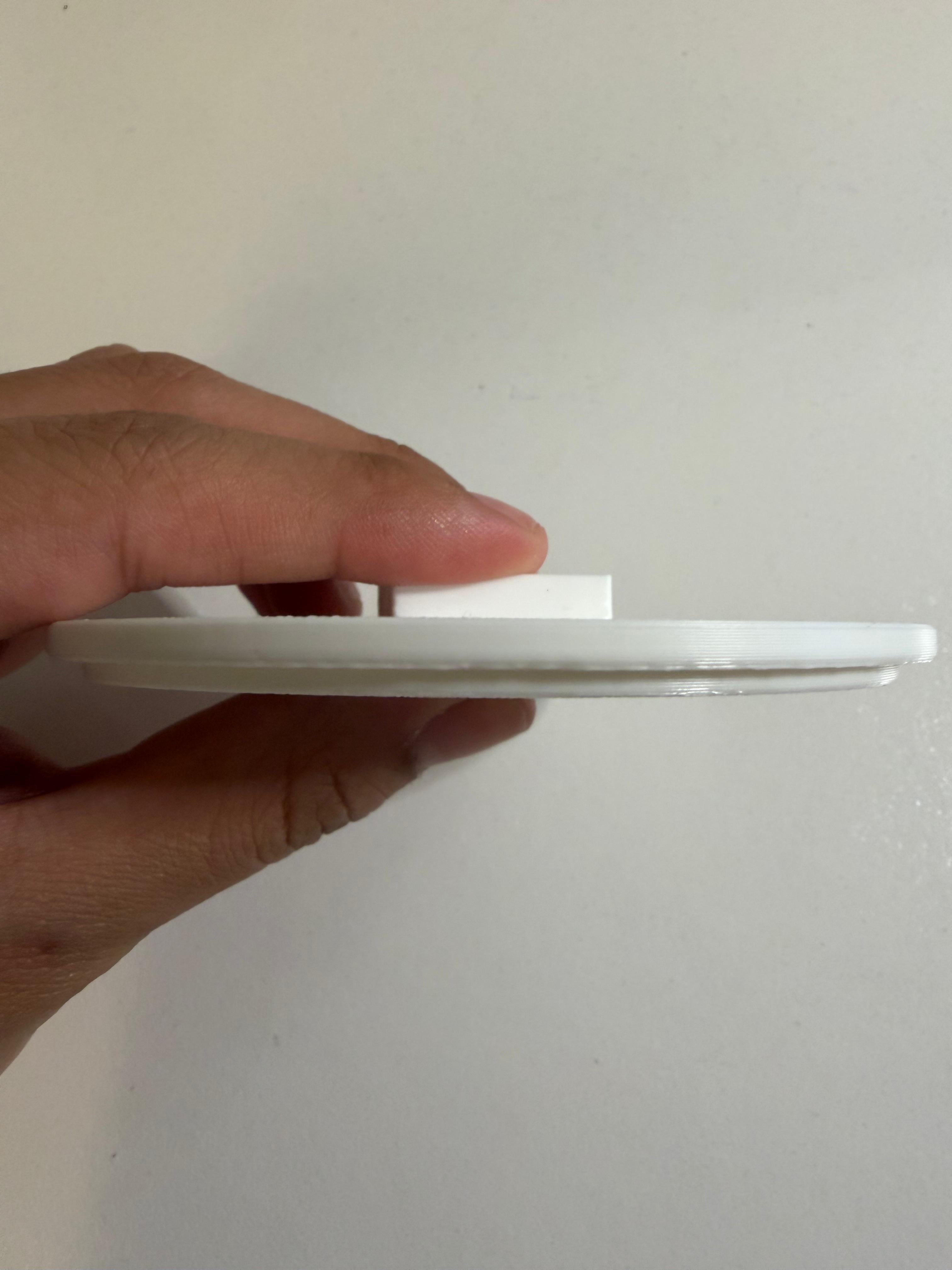
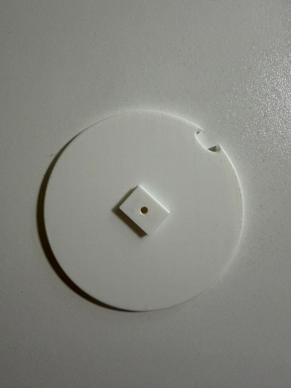
The dispensing mechanism. Includes a 3 mm center hole for the motor shaft and an 11 × 10 mm compartment for a single pill. When rotating, the disc aligns the pill with the output point for controlled and precise dispensing.
Parametric Modeling in Fusion 360
I used a hybrid design approach to create the multiple parts that would later be assembled.
Before modeling a single feature, I defined all key dimensions as named parameters, making the model fully adaptable from a single table.
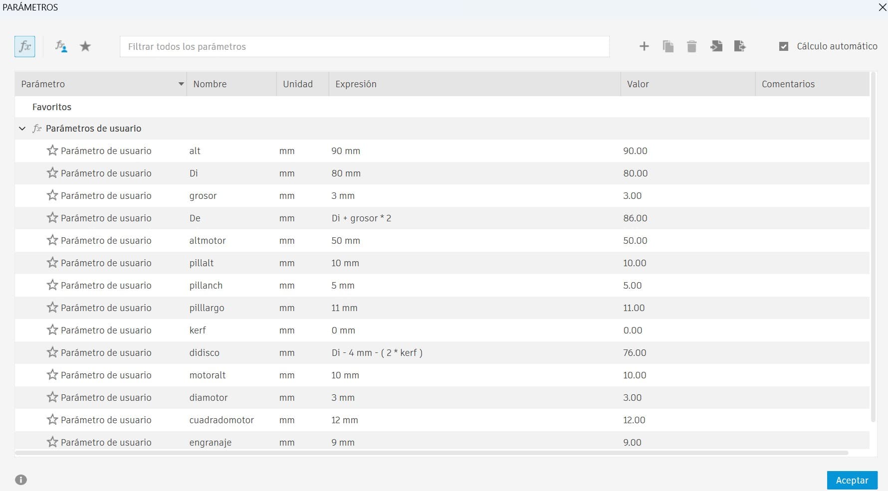
Compensates for 3D printing dimensional inaccuracies, adjustable per printer.
Key measurements automatically depend on each other. Change one value and the entire model updates.
Outer Diameter (De) was defined as a function of the inner diameter (Di) plus wall thickness, ensuring consistent walls at any scale.
New Modeling Tools Explored
Modeling the dispenser pushed me to expand my Fusion 360 toolkit. Here are the key tools and techniques I worked with for the first time:
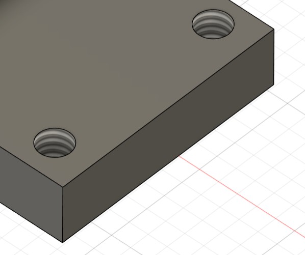
Chamfer, bevel & fillet — used to refine edges, soften transitions, and improve the overall finish of the design.
Offset & angled planes — essential for sketching and extruding complex geometry that doesn't sit on a standard axis.
Thread feature for functional screw holes, and symmetry to maintain accurate proportions across mirrored geometry.
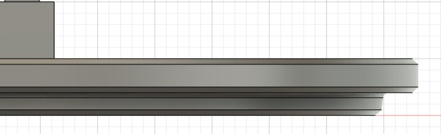
The most laborious part was designing the container and lid. The lid needed to be fully removable but fit with precision. Due to the closed geometry, I used the Section Analysis on the Y axis to verify internal alignment and ensure the lid was correctly seated inside the cylinder.
Component Models
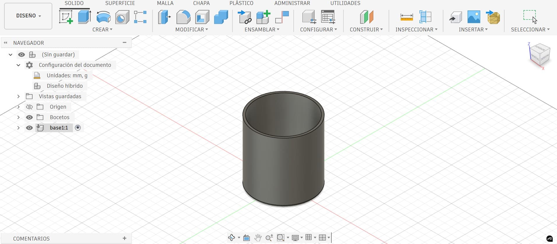
The cylinder acts as the structural body of the dispenser, providing stability and guiding the rotating disc. Wall thickness and internal tolerances were carefully defined as parameters to ensure smooth operation and structural integrity.
The N20 300 RPM motor was the reference for the support geometry. Since the design is fully parametric, changing motors only requires updating the relevant parameters and the entire model adapts automatically.
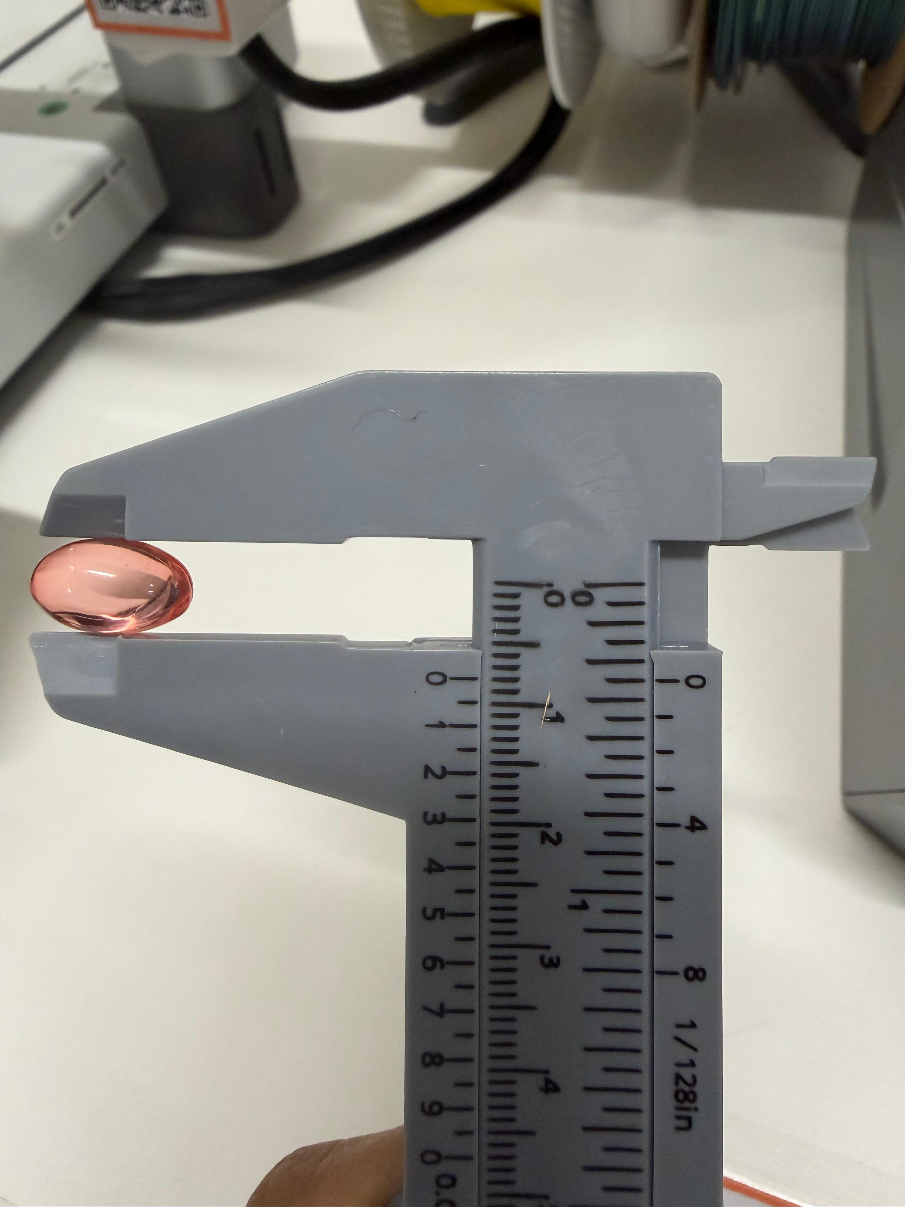
To ensure the dispensing disc correctly held and released a single pill, I measured one of my actual anti-cramp tablets with a vernier caliper to obtain precise dimensions, entered directly as parameters in the model.
Slicing & Printing on the Bambu Lab X1E
With the design finalized, I brought the model into Bambu Studio to slice it and convert it into G-code for the printer.
⚠️ First Attempt
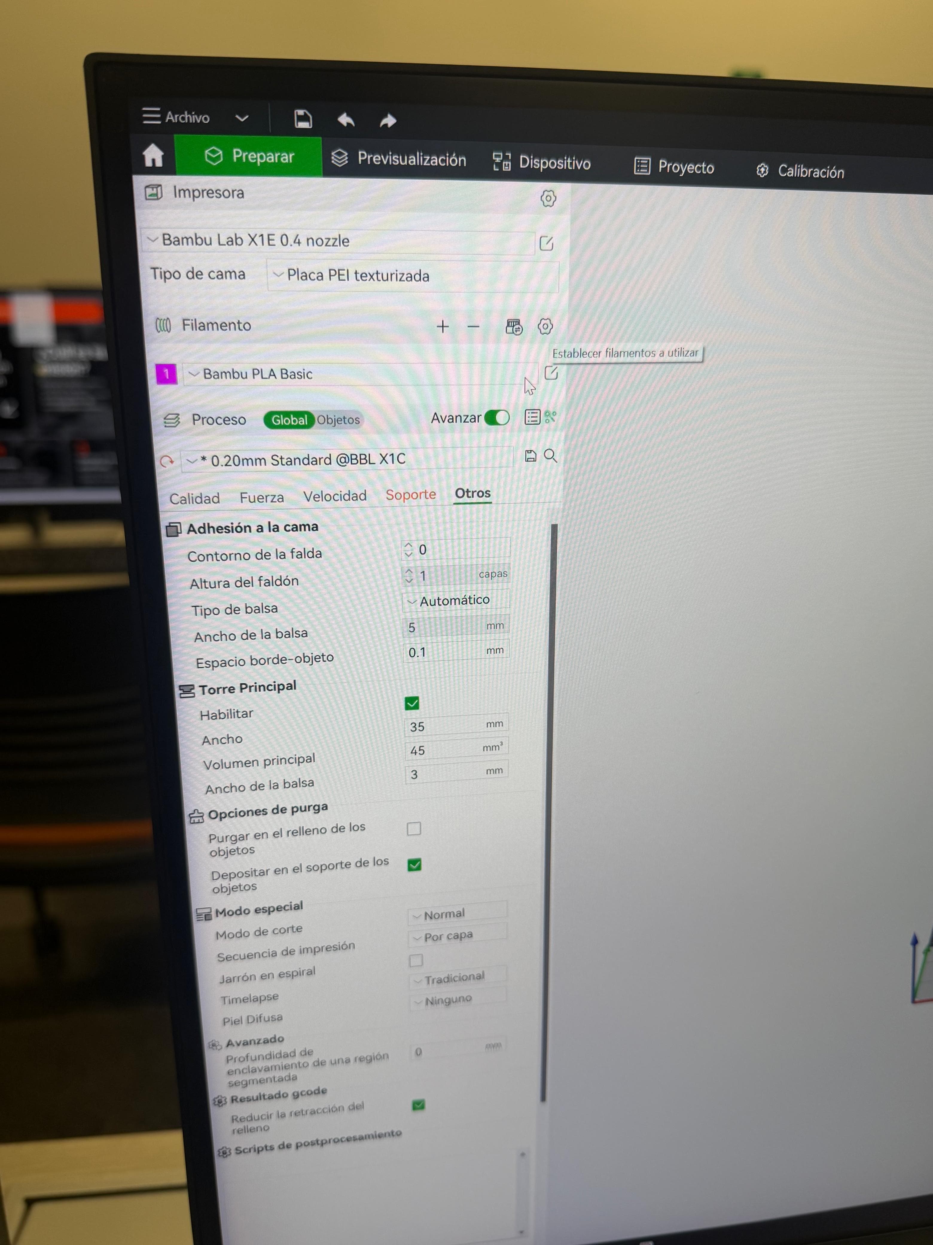
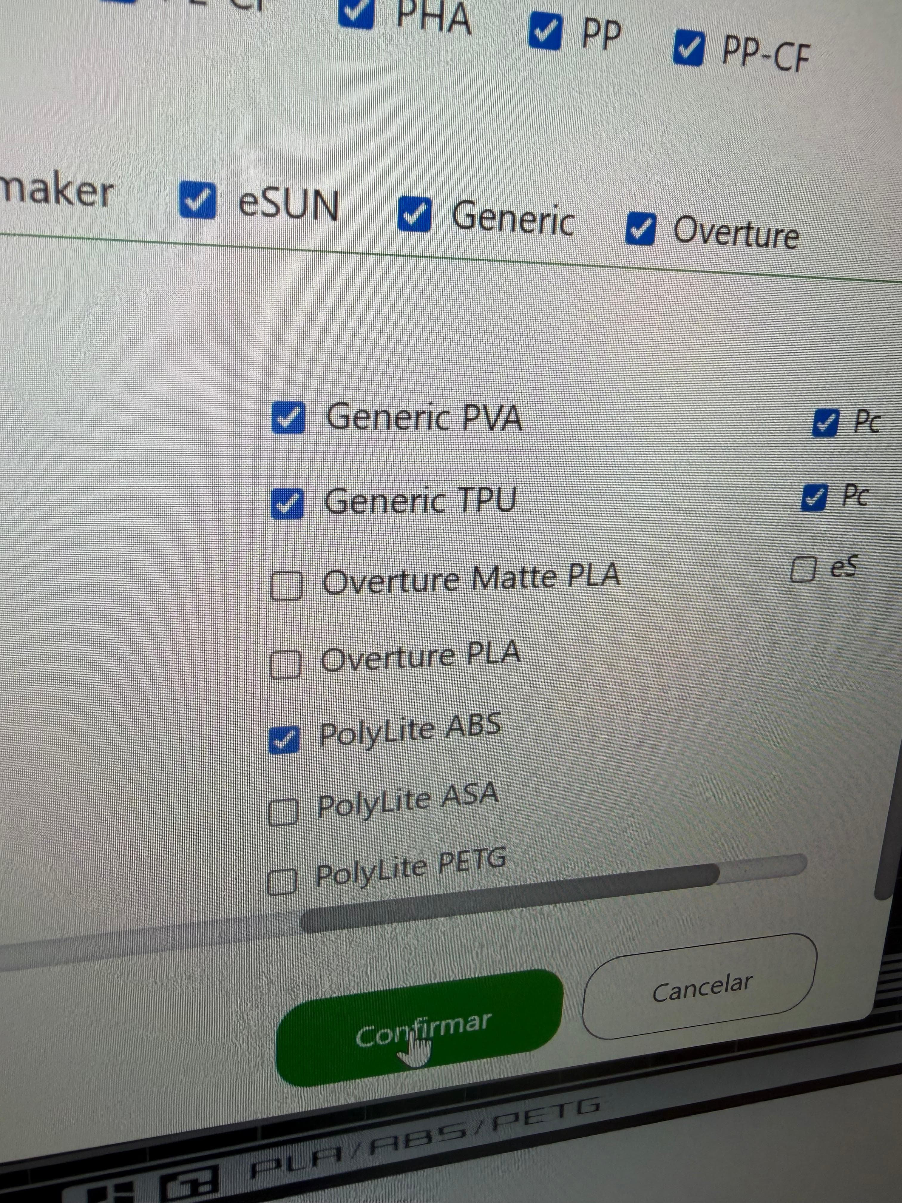
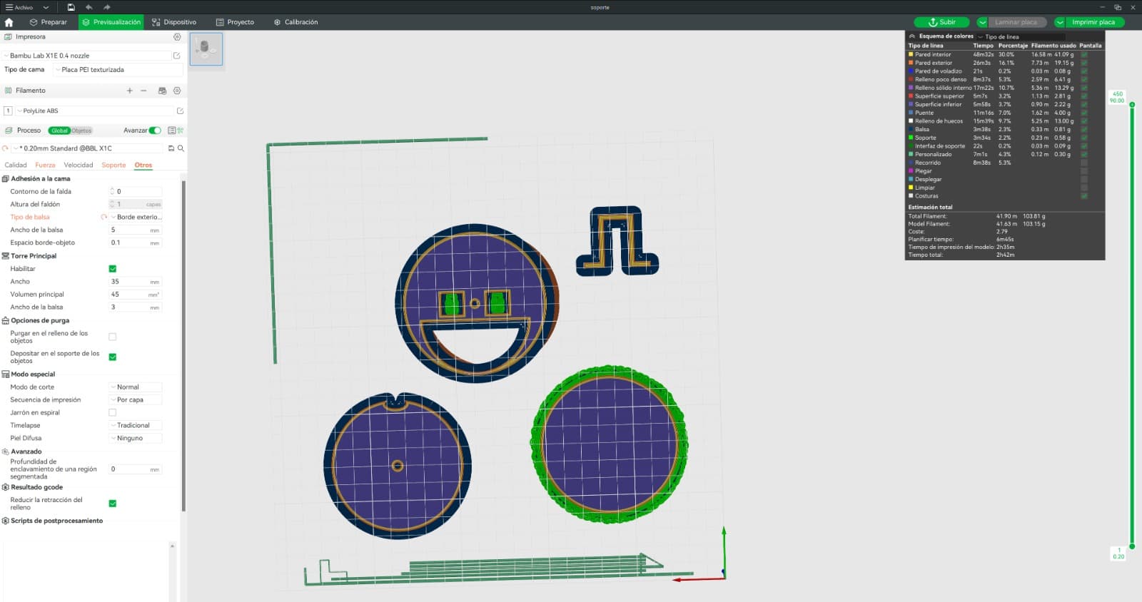
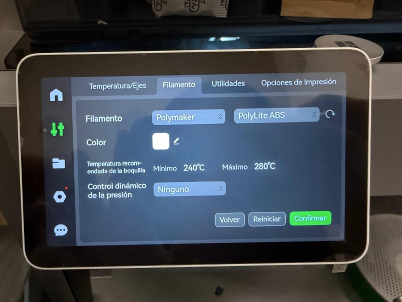
The software was configured for the Bambu Lab X1E with 0.4 mm nozzle. Since PolyLite ABS was not a default option, it was manually enabled from the Polymaker profile in the filament menu.
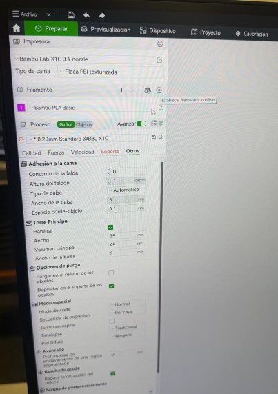
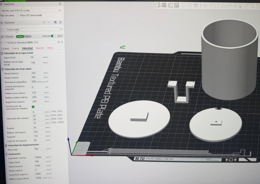
A standard quality profile was used with a layer height of 0.20 mm. Key settings:
- Inner wall speed: 300 mm/s to optimize total print time
- Supports: Tree supports enabled for easier removal
- Adhesion: Inner and outer brim to prevent ABS warping
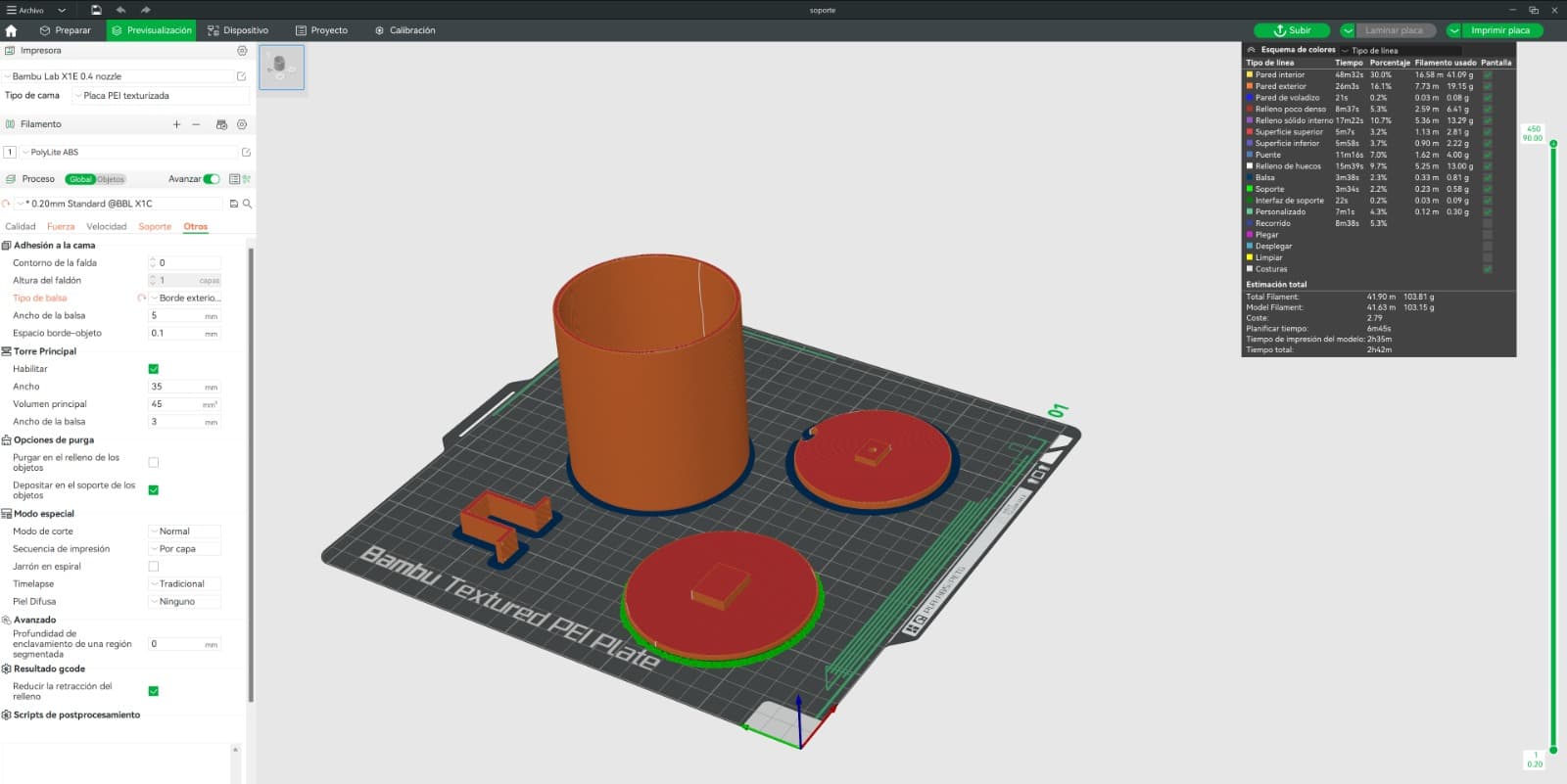
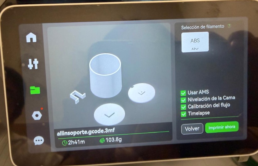
After the adjustments, the model was sliced. The preview confirmed an estimated time of 2 hours 41 minutes, using approximately 103.8 g of filament.
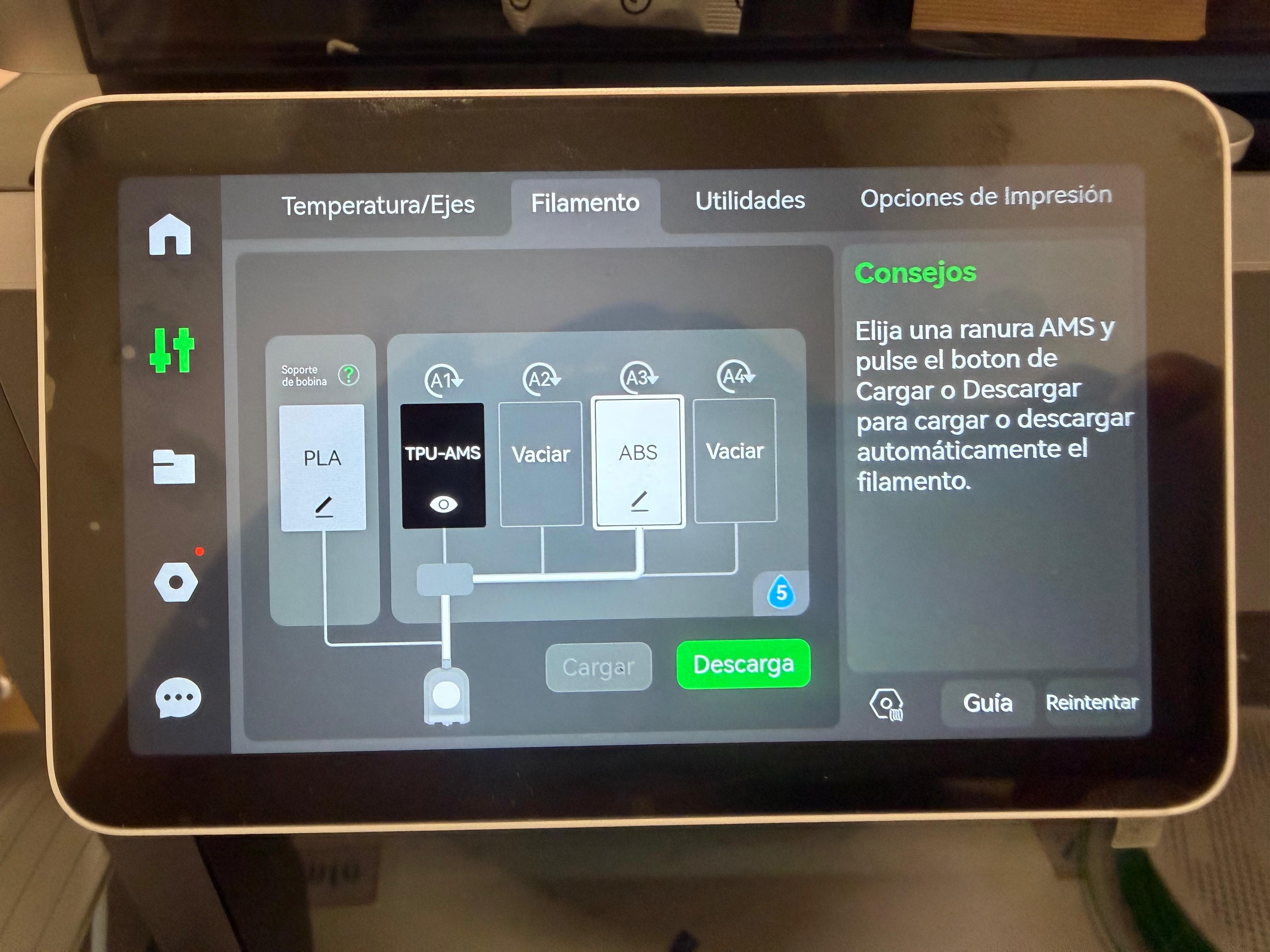
On the X1E touchscreen, PolyLite ABS was loaded into slot 3 (A3) of the AMS system, with the nozzle temperature configured between 240°C and 280°C.
The print job was started, activating Bed Leveling, Flow Calibration (essential for ABS precision), and Timelapse recording to document the process.
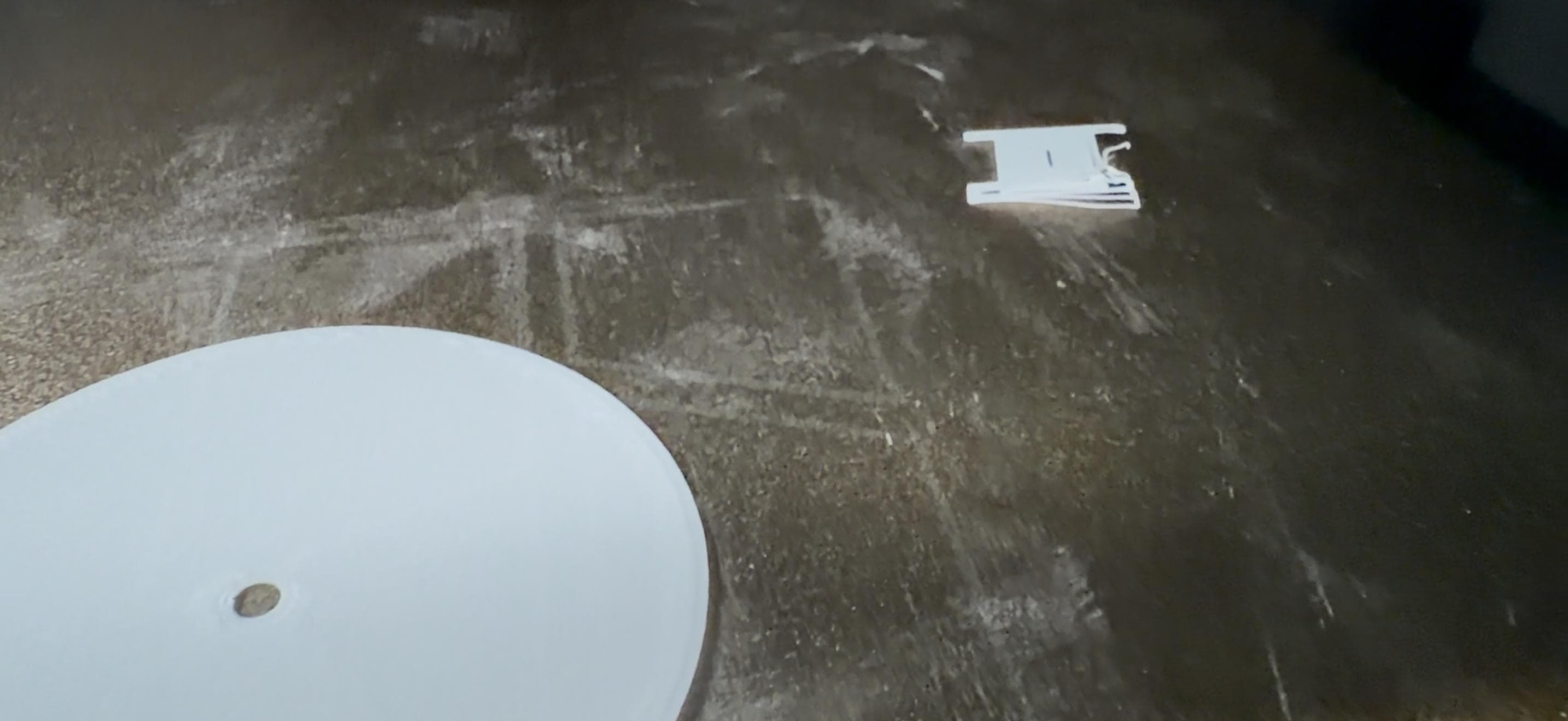
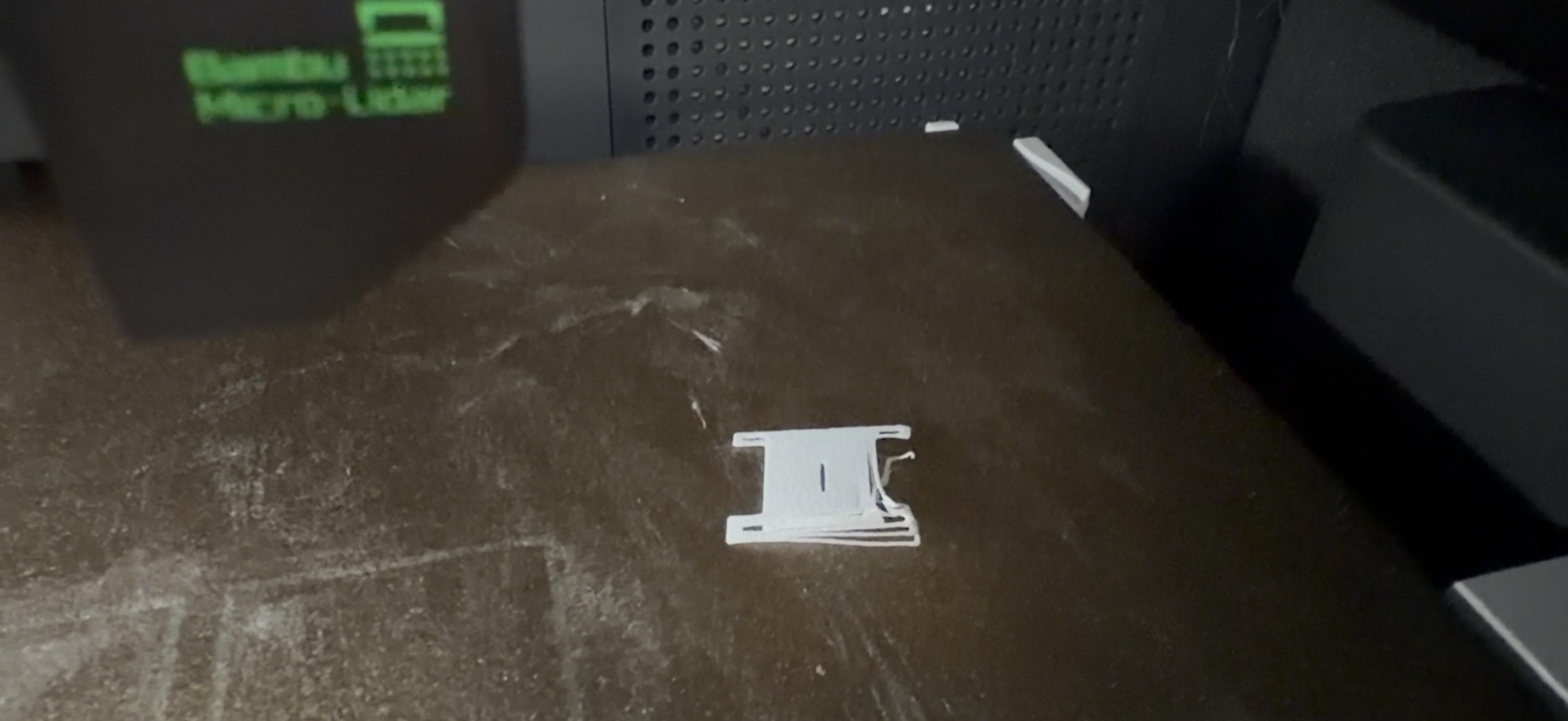
The lid fits and closes the container correctly, but needs a deeper inner extrusion to generate more friction and achieve a more secure closure. Tolerances must also account for ABS shrinkage.
The pill compartment is too small due to insufficient tolerance in the design. Compartments must be resized with actual pill dimensions plus a clearance margin.
The key improvement for the next iteration is to finalize the motor selection before designing the support. Motor dimensions directly affect internal space, mounting points, and the transmission system.
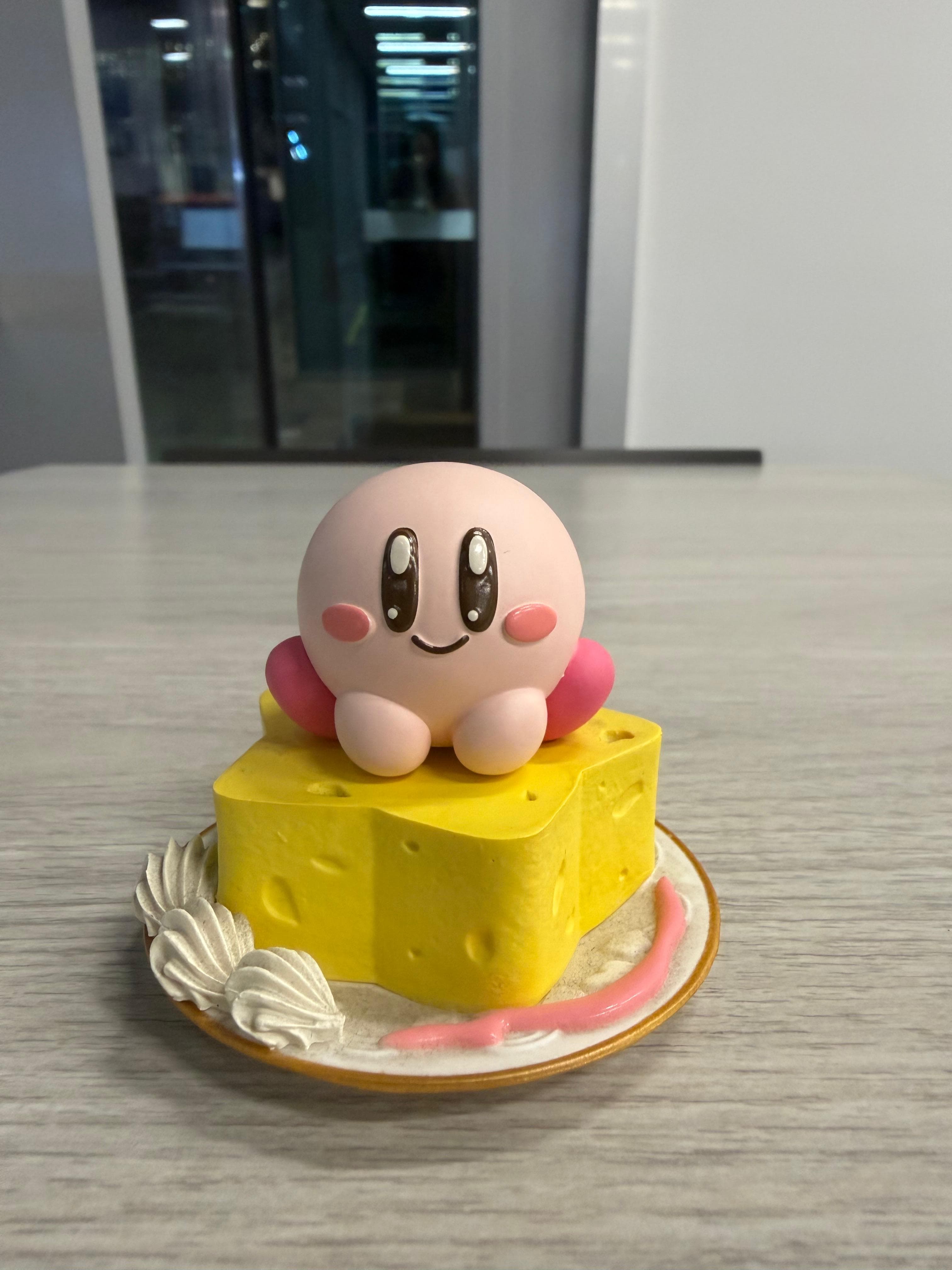
Capturing the Real World
I decided to scan my favorite Kirby figure. It has many small details, especially the snack pieces around the character. Our instructor recommended Scaniverse, a versatile and beginner-friendly mobile app: download it on any phone and generate detailed 3D models in minutes.

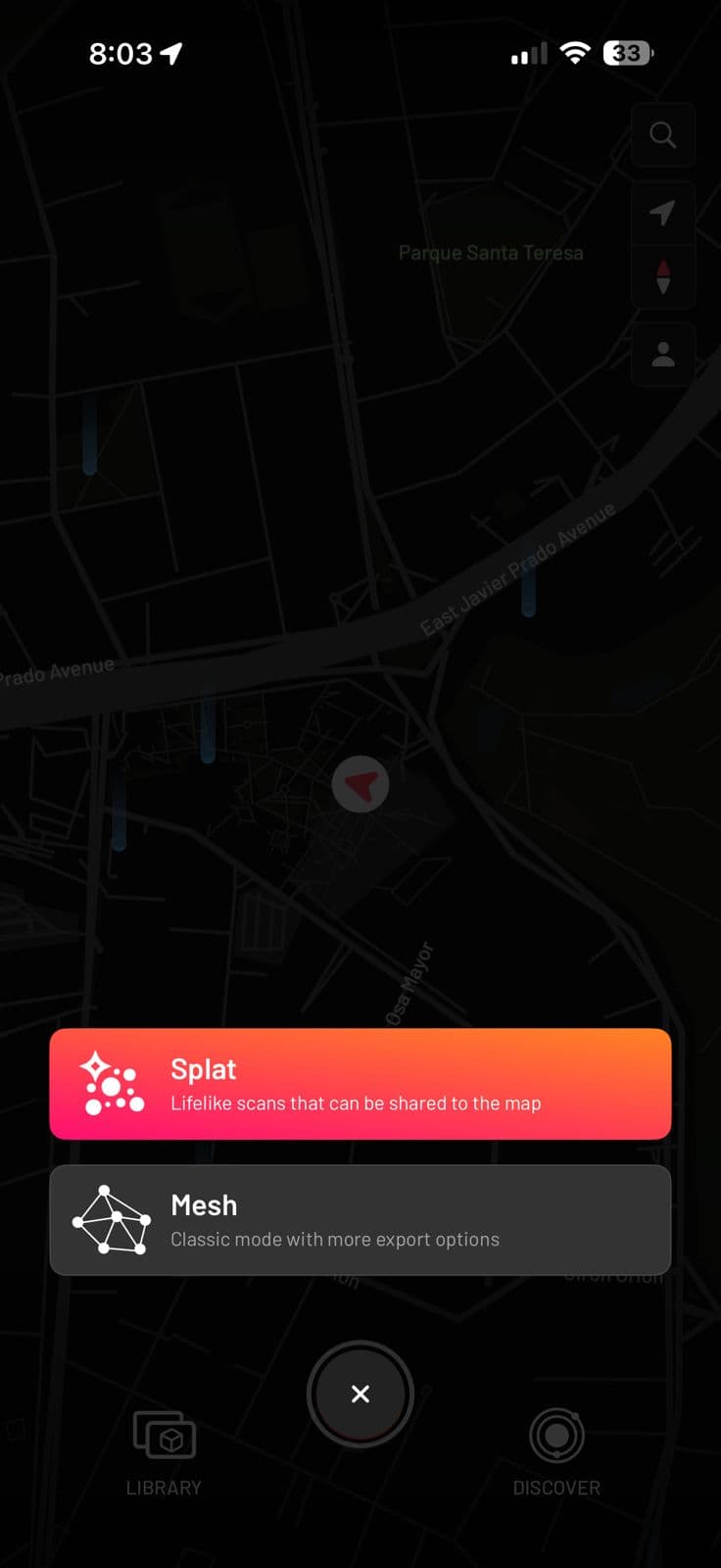
After creating an account, I selected the option to start a new scan and chose Mesh mode, designed for solid objects. (Splat mode is more suitable for flat surfaces or complex environments.)
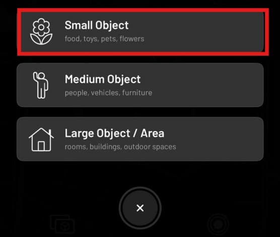
I selected Small Object, since the Kirby figure falls into the toy category. This option captures fine details with greater precision, important given the intricate elements around the figure.
I placed the figure on a flat surface and walked slowly around it with the phone, ensuring the app captured the object from all angles. I paid special attention to the sides and small details.

The model was exported in STL format for use in the following assignment steps.
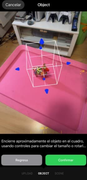
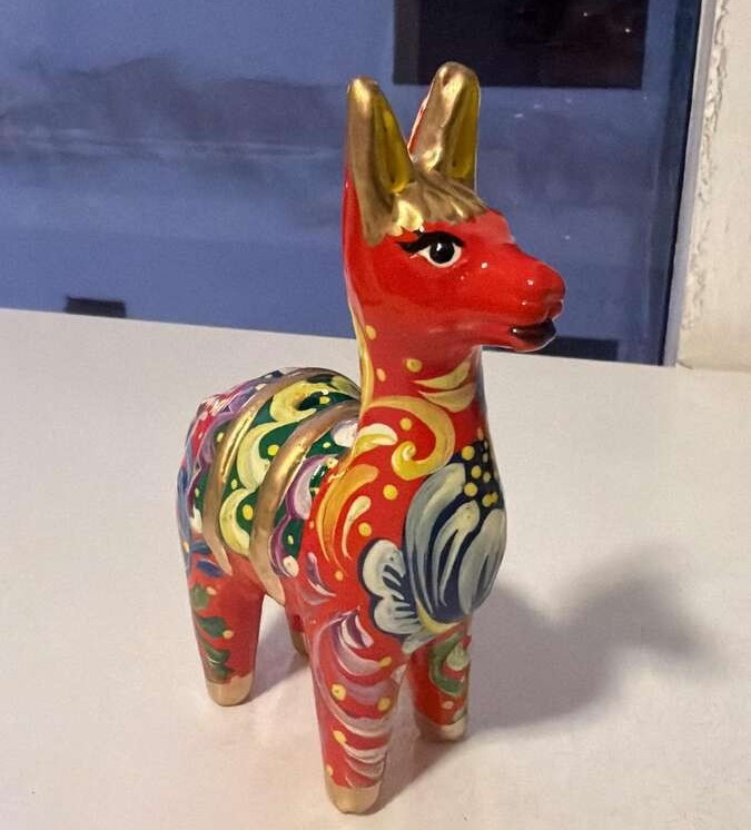
Not satisfied with the Scaniverse result, I found Luma 3D through Ofelia Sevilla's Week 5 documentation from Fab Academy 2025 at ULima. I also switched objects to a small alpaca figurine to explore additional options for the trophy project.
↗ Ofelia's Week 5
The scanning process is similar to Scaniverse but with two key advantages: Luma 3D shows in real time which areas have not yet been captured, and after scanning you can manually adjust the scan boundary to crop out unwanted surfaces like the table.