
Types of Connections Between Boards
There are two main types of communication between electronic boards: wireless (no physical cables required) and wired (uses physical connections). Understanding each type — and when to use it — is fundamental before designing any networked embedded system.
1. Wireless Communication
Bluetooth (Classic)
- One-to-one connection
- Example: HC-05 / HC-06 modules (often the "blue" ones)
- Moderate power consumption
- Used for simple serial communication
Bluetooth Low Energy (BLE)
- Very low power consumption
- Supports multiple connections
- Ideal for mobile apps, IoT, and battery-powered systems
Wi-Fi
- Allows communication over a network (internet or local)
- Higher power consumption than Bluetooth
- Suitable for cloud-based applications and remote control
2. Wired Communication
Wired communication uses physical connections (cables) between boards. It is divided into synchronous (devices share a clock signal) and asynchronous (no shared clock, devices agree on parameters like baud rate).
I2C — Synchronous
- Uses only 2 wires: SDA (data) and SCL (clock)
- Allows multiple devices on the same bus
- Each device has a unique address
- Commonly used for: displays (LCD), sensors
SPI — Synchronous
- Faster than I2C
- Uses more wires: MOSI, MISO, SCK, SS
- Used for displays, SD cards, etc.
UART — Asynchronous
- No clock signal is shared
- Devices must agree on parameters like baud rate
- Uses 2 wires: TX (transmit) and RX (receive)
- Used for: communication between boards, Serial Monitor
These were the types of communications our instructors suggested based on the use case:
Use UART (Serial) for simple, direct communication between two boards.
Use I2C when connecting multiple devices like sensors and displays.
Use BLE for low power & mobile integration. Use Wi-Fi for internet-based projects.
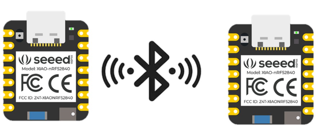
BLE Communication Between Two XIAO nRF52840
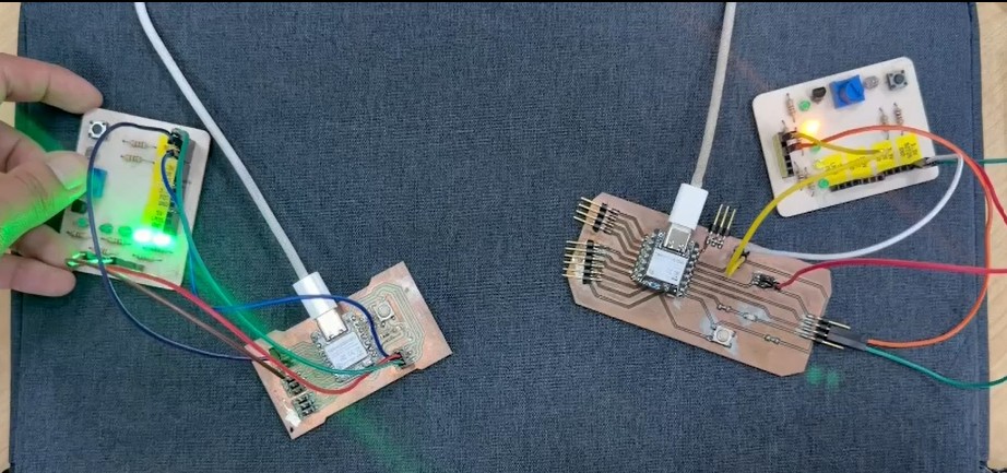
In the group assignment, we explored wireless communication between two XIAO nRF52840 boards by configuring one as a sender and the other as a receiver. Each board had a button and an LED. When the button on one PCB was pressed, it turned on the LED on the other board, demonstrating real-time data exchange via Bluetooth.
To implement this, we researched how Bluetooth works on the XIAO nRF52840 using the official Seeed Studio documentation:
↗ Seeed Studio XIAO BLE DocumentationWhy BLE?
Ideal for battery-powered systems like CNC machines or small robots (e.g., 7.5V supply).
BLE sends simple data (like a button state or command), which fits our code using ledChar.write8(pressed).
The goal was to create a system between two microcontrollers using a Central–Peripheral architecture, the core model of Bluetooth Low Energy. One XIAO nRF52840 acted as the Peripheral, and the other as the Central, allowing real-time wireless communication.
The Peripheral works as a server: advertising its presence and providing a BLE Service with a Characteristic that stores the data shared between devices. After understanding this structure, we started coding.
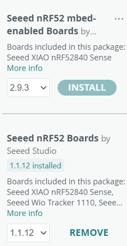
#include <bluefruit.h> library was not available and needed to be replaced with ArduinoBLE.#include <bluefruit.h>
#define LED_PIN LED_BUILTIN
BLEClientService customService(0x1234);
BLEClientCharacteristic customChar(0x5678);
bool isConnecting = false;
void connect_callback(uint16_t conn_handle) {
isConnecting = false;
if (customService.discover(conn_handle)) {
digitalWrite(LED_PIN, HIGH);
} else {
Bluefruit.disconnect(conn_handle);
}
}
void disconnect_callback(uint16_t conn_handle, uint8_t reason) {
digitalWrite(LED_PIN, LOW);
delay(300);
Bluefruit.Scanner.start(0);
}
void scan_callback(ble_gap_evt_adv_report_t* report) {
if (isConnecting) return;
if (Bluefruit.Scanner.checkReportForService(report, customService)) {
isConnecting = true;
Bluefruit.Scanner.stop();
Bluefruit.Central.connect(report);
} else {
Bluefruit.Scanner.resume();
}
}
void setup() {
pinMode(LED_PIN, OUTPUT);
digitalWrite(LED_PIN, LOW);
Bluefruit.begin(0, 1);
Bluefruit.setTxPower(4);
Bluefruit.setName("XIAO_CENTRAL");
Bluefruit.Central.setConnectCallback(connect_callback);
Bluefruit.Central.setDisconnectCallback(disconnect_callback);
customService.begin();
customChar.begin();
Bluefruit.Scanner.setRxCallback(scan_callback);
Bluefruit.Scanner.restartOnDisconnect(true);
Bluefruit.Scanner.setInterval(160, 80);
Bluefruit.Scanner.useActiveScan(true);
Bluefruit.Scanner.start(0);
}
void loop() {}
Once we installed the correct libraries (ArduinoBLE) and removed the incorrect ones, we were able to continue.
XIAO nRF52840 — Peripheral
#include <ArduinoBLE.h>
const int BUTTON_PIN = D2;
const int LED_PIN    = D9;

BLEService buttonService("180C");
BLEByteCharacteristic buttonChar("2A56", BLERead | BLENotify);

byte lastButtonState = 0;

void setup() {
  pinMode(BUTTON_PIN, INPUT_PULLUP);
  pinMode(LED_PIN, OUTPUT);
  digitalWrite(LED_PIN, LOW);
  Serial.begin(9600);
  while (!Serial);
  if (!BLE.begin()) { Serial.println("BLE failed to start"); while (1); }
  BLE.setLocalName("XIAO_PERIPHERAL");
  BLE.setAdvertisedService(buttonService);
  buttonService.addCharacteristic(buttonChar);
  BLE.addService(buttonService);
  buttonChar.writeValue((byte)0);
  BLE.advertise();
  Serial.println("Peripheral advertising...");
}

void loop() {
  BLEDevice central = BLE.central();
  if (central) {
    Serial.print("Connected to central: ");
    Serial.println(central.address());
    while (central.connected()) {
      byte currentButtonState = (digitalRead(BUTTON_PIN) == LOW) ? 1 : 0;
      if (currentButtonState != lastButtonState) {
        buttonChar.writeValue(currentButtonState);
        if (currentButtonState == 1) {
          digitalWrite(LED_PIN, HIGH);
          Serial.println("Button pressed - sent 1");
        } else {
          digitalWrite(LED_PIN, LOW);
          Serial.println("Button released - sent 0");
        }
        lastButtonState = currentButtonState;
      }
      delay(20);
    }
    Serial.println("Central disconnected");
    digitalWrite(LED_PIN, LOW);
  }
}
"180C", "2A56"). This allows the Central device to locate and access the specific information it needs.XIAO nRF52840 — Central
#include <ArduinoBLE.h>
const int LED_PIN = D8;

BLEDevice peripheral;
BLECharacteristic buttonChar;

void setup() {
  pinMode(LED_PIN, OUTPUT);
  digitalWrite(LED_PIN, LOW);
  Serial.begin(9600);
  while (!Serial);
  if (!BLE.begin()) { Serial.println("BLE failed to start"); while (1); }
  Serial.println("Central scanning for peripheral...");
  BLE.scan();
}

void loop() {
  peripheral = BLE.available();
  if (peripheral) {
    if (peripheral.localName() == "XIAO_PERIPHERAL") {
      BLE.stopScan();
      if (connectToPeripheral(peripheral)) {
        while (peripheral.connected()) {
          if (buttonChar.valueUpdated()) {
            byte value;
            buttonChar.readValue(value);
            if (value == 1) {
              digitalWrite(LED_PIN, HIGH);
              Serial.println("Received 1 - LED ON");
            } else {
              digitalWrite(LED_PIN, LOW);
              Serial.println("Received 0 - LED OFF");
            }
          }
          delay(20);
        }
        Serial.println("Peripheral disconnected");
        digitalWrite(LED_PIN, LOW);
      }
      BLE.scan();
    }
  }
}

bool connectToPeripheral(BLEDevice peripheral) {
  if (!peripheral.connect()) { return false; }
  if (!peripheral.discoverAttributes()) { peripheral.disconnect(); return false; }
  buttonChar = peripheral.characteristic("2A56");
  if (!buttonChar) { peripheral.disconnect(); return false; }
  if (!buttonChar.canSubscribe()) { peripheral.disconnect(); return false; }
  if (!buttonChar.subscribe()) { peripheral.disconnect(); return false; }
  Serial.println("Subscribed to characteristic");
  return true;
}
This project demonstrates bidirectional communication between two boards, where each one includes a button (input) and an LED (output). Pressing a button on one board sends a signal to the other, triggering its LED — and the same occurs in reverse. This confirms continuous real-time data exchange using defined data structures through BLE services and characteristics.
Key Concepts
- <bluefruit.h> library: This Adafruit library is specifically designed for nRF52840 modules and focused on BLE — however it was not the correct choice for our setup.
- Client and Service concepts: The code defines a
BLEClientServiceand aBLEClientCharacteristic. These are fundamental building blocks of BLE (based on the GATT profile), where a device searches for specific services and characteristics using UUIDs. - Scanning and advertising: Functions like
Bluefruit.Scanner.start()andBluefruit.Central.connect()are typical of a Central in a BLE network, scanning for and connecting to a Peripheral.
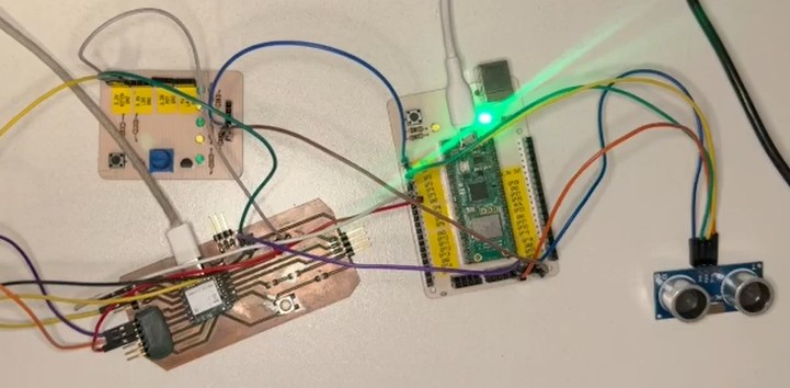
Distributed Control System: XIAO "The Brain" & Pico "The Worker"
I started this project with a lot of excitement and a desk full of sensors. My first instinct was to connect everything I could find — ultrasound, buttons, motors. The challenge wasn't just making them work, but making two different microcontrollers talk to each other to share the workload.
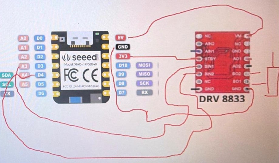
The Seeed Studio XIAO nRF52840 was designated as the Central Brain. The motor control (simulated via PWM) was handled by the Pico, which needed to obey commands from the XIAO. When the button on the XIAO was pressed, it sent a command to the Pico to increase the motor's power, creating a "boost" effect.
const int PIN_BOTON = 0;
const int MOTOR_B1 = 10;
const int MOTOR_B2 = 9;

void setup() {
  pinMode(MOTOR_B1, OUTPUT);
  pinMode(MOTOR_B2, OUTPUT);
  pinMode(LED_RED, OUTPUT);
  pinMode(PIN_BOTON, INPUT); // Waits to receive 3.3V
  digitalWrite(MOTOR_B1, LOW);
  digitalWrite(MOTOR_B2, LOW);
  digitalWrite(LED_RED, HIGH); // Off
}

void loop() {
  if (digitalRead(PIN_BOTON) == HIGH) {
    digitalWrite(MOTOR_B1, HIGH);
    digitalWrite(MOTOR_B2, LOW);
    digitalWrite(LED_RED, LOW); // Red LED turns on
  } else {
    digitalWrite(MOTOR_B1, LOW);
    digitalWrite(MOTOR_B2, LOW);
    digitalWrite(LED_RED, HIGH);
  }
}
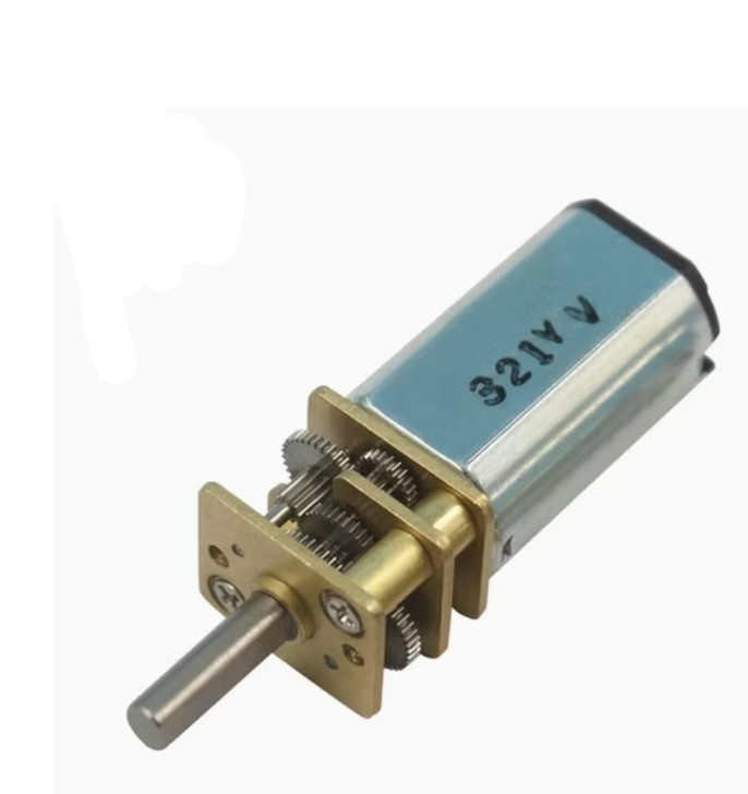
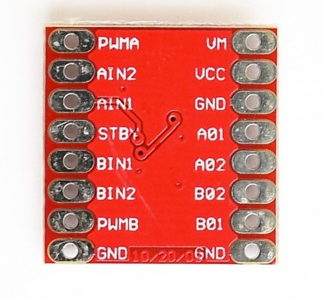
In this project, I used a 5V–12V Mini DC Geared Motor. A motor driver is required because the microcontroller GPIO pins only provide control signals (3.3V) and very limited current. The DRV8833 driver acts as an intermediary, allowing the microcontroller to control the motor safely.
↗ Motor ReferenceIn this setup, the microcontroller provides sufficient current for this small motor. The board is powered through USB, and the microcontroller distributes that power to the driver and motor. This means the motor is not powered directly by the laptop, but by the microcontroller's power output sourced from USB.
Initially, I connected the HC-SR04 ultrasonic sensor and the OLED display directly to the Pico. The goal was for the Pico to handle everything — measurement and visualization — on its own. It worked, but I realized that as the project grew, a more modular approach was needed.
from machine import Pin, I2C
import utime
import framebuf

i2c = I2C(0, sda=Pin(4), scl=Pin(5), freq=400000)
trig = Pin(2, Pin.OUT)
echo = Pin(1, Pin.IN)

class OLED:
    def __init__(self, i2c):
        self.i2c = i2c
        self.addr = 0x3C
        self.buffer = bytearray(1024)
        self.fb = framebuf.FrameBuffer(self.buffer, 128, 64, framebuf.MONO_VLSB)
        self.init_display()

    def write_cmd(self, cmd):
        try: self.i2c.writeto(self.addr, bytearray([0x00, cmd]))
        except: pass

    def init_display(self):
        for cmd in (0xAE, 0x20, 0x00, 0x21, 0, 127, 0x22, 0, 7, 0x8D, 0x14, 0xAF, 0xA4, 0xA6):
            self.write_cmd(cmd)
        self.clear_physical()

    def clear_physical(self):
        self.fb.fill(0)
        self.show()

    def show(self):
        self.write_cmd(0x21); self.write_cmd(0); self.write_cmd(127)
        self.write_cmd(0x22); self.write_cmd(0); self.write_cmd(7)
        try: self.i2c.writeto(self.addr, b'\x40' + self.buffer)
        except: pass

    def power_off(self):
        self.clear_physical()
        self.write_cmd(0xAE)

    def power_on(self):
        self.write_cmd(0xAF)

oled = OLED(i2c)
estado_anterior = False

def medir():
    trig.low(); utime.sleep_us(2); trig.high(); utime.sleep_us(10); trig.low()
    start = utime.ticks_us()
    while echo.value() == 0:
        if utime.ticks_diff(utime.ticks_us(), start) > 20000: return -1
    t1 = utime.ticks_us()
    while echo.value() == 1:
        if utime.ticks_diff(utime.ticks_us(), t1) > 20000: break
    t2 = utime.ticks_us()
    return (utime.ticks_diff(t2, t1) * 0.0343) / 2

while True:
    dist = medir()
    detectado = (0 < dist <= 20)
    if detectado:
        if not estado_anterior:
            oled.power_on()
        oled.fb.fill(0)
        oled.fb.rect(0, 0, 128, 64, 1)
        oled.fb.text("PROXIMIDAD", 25, 10)
        oled.fb.hline(10, 22, 108, 1)
        oled.fb.text("{:.1f} cm".format(dist), 35, 35)
        ancho_barra = int((dist / 20) * 100)
        oled.fb.rect(14, 50, 100, 7, 1)
        oled.fb.fill_rect(14, 50, 100 - ancho_barra, 7, 1)
        oled.show()
        estado_anterior = True
    else:
        if estado_anterior:
            oled.power_off()
            estado_anterior = False
    utime.sleep_ms(50)
To simplify the hardware, both the SSD1306 OLED display and the HC-SR04 ultrasonic sensor were connected directly to the 3.3V rail of the Raspberry Pi Pico 2. The OLED natively supports 3.3V operation. The HC-SR04, however, is typically powered at 5V and its Echo pin outputs 5V, which is unsafe for the 3.3V-only GPIO of the Pico 2.
The system remains electrically stable due to low current consumption:
- HC-SR04 at 3.3V: ~10–15 mA
- SSD1306 OLED: ~20 mA
- Total: ~35 mA (well below the 300 mA available from the Pico 2 3V3 output)
Everything was going well until I realized a major physical constraint: I2C Pin Availability. I only had one set of SDA/SCL pins exposed, which made it extremely difficult to connect the OLED display and simultaneously use I2C for inter-board communication. The wiring was becoming a "spaghetti" mess.
| Feature | UART (Chosen Solution) | I2C (Initial Plan) |
|---|---|---|
| Wiring | Direct: TX to RX / RX to TX | Shared: Needs pull-up resistors |
| Independence | Runs on different pins than the OLED | Competes for the same SDA/SCL pins |
| Speed | Excellent for point-to-point data | Great for many small sensors |
| Advantage | Robust and easy to debug | Can connect up to 127 devices |
The final system operates with a clear hierarchy between the two microcontrollers:
- User Input: Monitors the button on D2
- Visuals: Controls the OLED Display via I2C
- Decision Making: If distance from Pico < 15cm, wakes OLED and displays "ALERTA!"
- Commands: Tells the Pico to turn off/on LED/Motor based on button state
- Eyes: Measures distance with HC-SR04 (Trig: GP2, Echo: GP1)
- Ears: Listens for commands from the XIAO via UART
- Hands: Controls the output on GP0 using PWM
XIAO nRF52840 — Arduino Code
#include <SoftwareSerial.h>
#include <Wire.h>
#include <Adafruit_GFX.h>
#include <Adafruit_SSD1306.h>

#define SCREEN_WIDTH 128
#define SCREEN_HEIGHT 64
Adafruit_SSD1306 display(SCREEN_WIDTH, SCREEN_HEIGHT, &Wire, -1);
SoftwareSerial miSerial(0, 6);
const int BTN = 2;

int ultimoEstadoBtn = -1;
int ultimaDistanciaSubida = -1;
bool modoAlertaActivo = false;

void setup() {
  miSerial.begin(9600);
  pinMode(BTN, INPUT_PULLUP);
  if(!display.begin(SSD1306_SWITCHCAPVCC, 0x3C)) for(;;);
  Wire.setClock(400000);
  display.clearDisplay();
  display.display();
}

void loop() {
  // 1. BUTTON (Edge detection — highest priority)
  int estadoActualBtn = digitalRead(BTN);
  if (estadoActualBtn != ultimoEstadoBtn) {
    if (estadoActualBtn == LOW) miSerial.write('F'); // Pressed -> Off
    else miSerial.write('N');                        // Released -> On
    ultimoEstadoBtn = estadoActualBtn;
  }
  // 2. DISPLAY (Only if data is available from Pico)
  if (miSerial.available() > 0) {
    int distLeida = miSerial.read();
    if (distLeida < 15 && distLeida > 0) {
      if (abs(distLeida - ultimaDistanciaSubida) >= 2 || !modoAlertaActivo) {
        display.clearDisplay();
        display.setTextSize(2);
        display.setTextColor(SSD1306_WHITE);
        display.setCursor(20, 10);
        display.print("ALERTA!");
        display.setCursor(20, 40);
        display.print(distLeida); display.print(" cm");
        display.display();
        ultimaDistanciaSubida = distLeida;
        modoAlertaActivo = true;
      }
    } else if (modoAlertaActivo) {
      display.clearDisplay();
      display.display();
      modoAlertaActivo = false;
      ultimaDistanciaSubida = -1;
    }
  }
}
Raspberry Pi Pico 2W — MicroPython Code
from machine import Pin, UART
import utime

uart = UART(1, baudrate=9600, tx=Pin(4), rx=Pin(5))
led_pico = Pin(0, Pin.OUT, value=1)  # Starts on
trig = Pin(2, Pin.OUT)
echo = Pin(1, Pin.IN)

def medir():
    trig.low(); utime.sleep_us(2); trig.high(); utime.sleep_us(10); trig.low()
    start = utime.ticks_us()
    while echo.value() == 0:
        if utime.ticks_diff(utime.ticks_us(), start) > 10000: return 0
    t1 = utime.ticks_us()
    while echo.value() == 1:
        if utime.ticks_diff(utime.ticks_us(), t1) > 10000: break
    return int((utime.ticks_diff(utime.ticks_us(), t1) * 0.0343) / 2)

while True:
    # 1. Read button command (INSTANT)
    if uart.any():
        cmd = uart.read(1)
        if cmd == b'F': led_pico.off()
        elif cmd == b'N': led_pico.on()

    # 2. Measure and send distance (non-blocking)
    d = medir()
    if d > 0:
        uart.write(bytes([min(d, 255)]))

    utime.sleep_ms(10)  # Minimal delay for stability
| Component | XIAO — The Brain | Pico — The Worker |
|---|---|---|
| UART Communication | D6 (TX) / D0 (RX) | GP5 (RX) / GP4 (TX) |
| OLED Display | D4 (SDA) / D5 (SCL) | — |
| Button | D2 | — |
| Ultrasonic Sensor | — | GP2 (Trig) / GP1 (Echo) |
| LED / Motor Output | — | GP0 |
| Ground | GND | GND |
Getting Started with Raspberry Pi Pico 2W
Connect the Raspberry Pi Pico 2W to the laptop using a Micro-USB cable. In some cases, the laptop automatically recognizes it as a USB drive. If it does not appear or does not respond in Thonny, it may be necessary to install the MicroPython firmware. In my case, the device was recognized automatically.
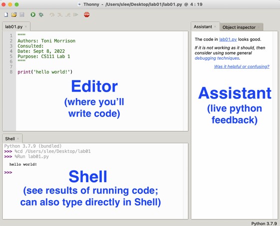
Download Thonny from the official page: https://thonny.org/

- Download the Windows version
- Run the installer
- Next → Next → Install → Finish
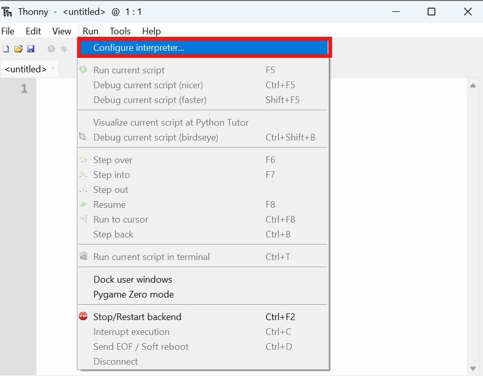
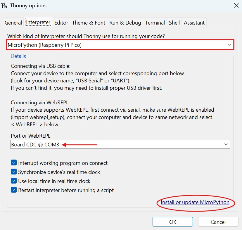
Once Thonny is open: go to Run → Configure Interpreter. In "Interpreter" select MicroPython (Raspberry Pi Pico). In "Port" select the port that appears automatically.
- Disconnect the Raspberry
- Hold down the BOOTSEL button
- Reconnect it to the laptop without releasing the button
- It will appear as a USB drive
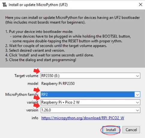
- In Thonny: Go to Run → Configure Interpreter → Install or update MicroPython
- Board: Raspberry Pi Pico / Pico W
- Select the correct port
- Click Install then OK
After installing, in the Thonny console (Shell) you should see something like: