
What Is Power Consumption?
Power consumption refers to the amount of electrical energy used by a device or system during operation. It is an important factor when evaluating efficiency, performance, and energy costs.
⚡ The Core Formula
Where:
- P = Power (Watts)
- V = Voltage (Volts)
- I = Current (Amperes)
Cover any variable in the triangle to find the formula for that value.
📐 Alternative Formulas
Use when you know current flow and resistance of the load.
Use when you know voltage across the load and its resistance.
🔁 Unit Conversions
Measuring Motor Power Consumption
If you want to see more about the Group Assignment, you can visit the official Fab Academy page:
Visit Fab Academy ULima🔧 1. System Description
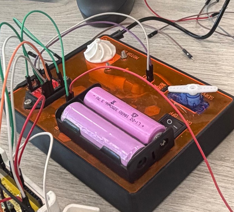
We measured the output of a motor demonstration kit available in our Fab Lab. The system consisted of the following components:
Dual H-bridge motor driver capable of up to 1.2 A continuous current per channel. Controls motor direction and speed via PWM signals from the MCU.
Rechargeable lithium-ion cell used as the external power source for the motor circuit. Note: our unit showed signs of wear during testing.
Standard dual-shaft TT gear motor. Rated at 6V with a no-load speed of 200 RPM, common in robotics and educational kits.
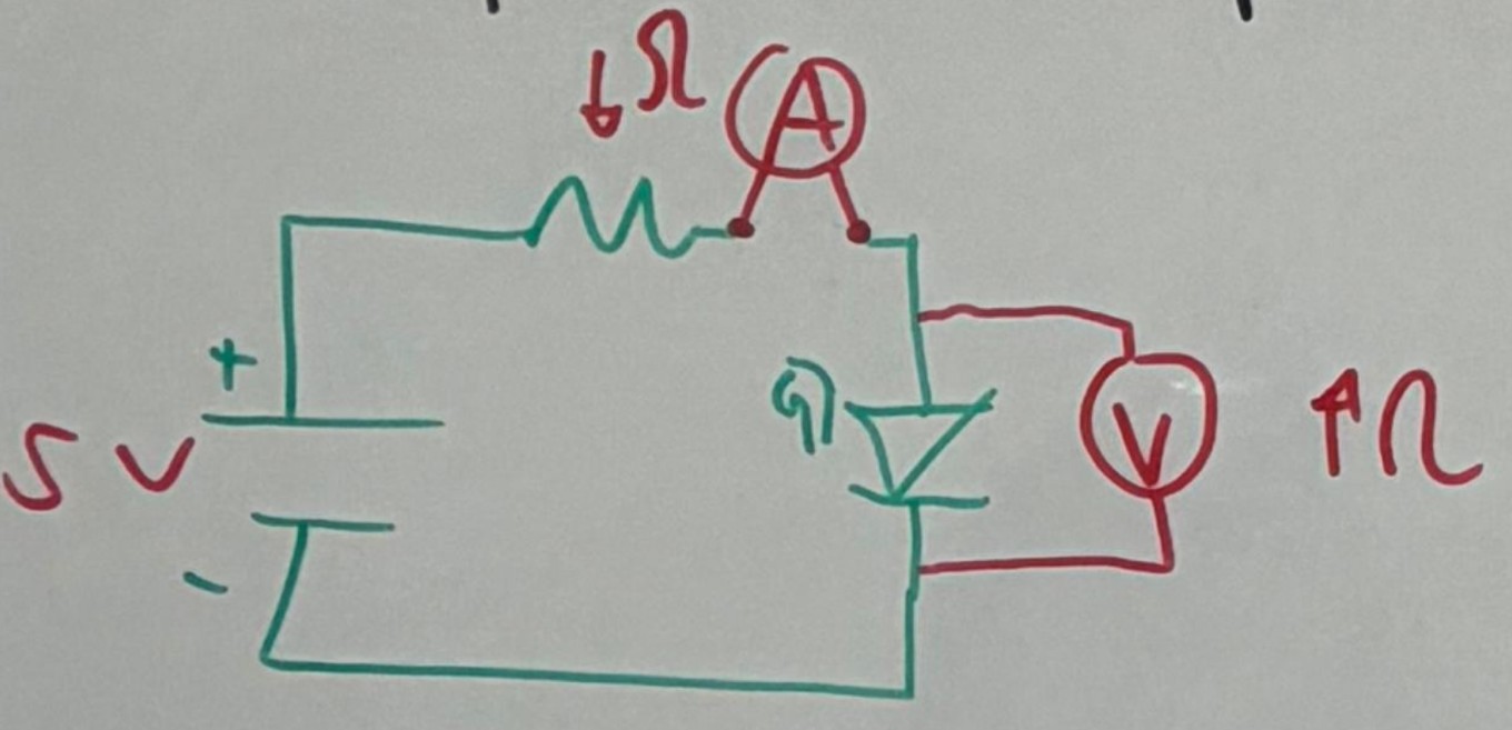
📏 2. Measurement Methodology
To analyze the system we connected two multimeters simultaneously — one to measure voltage and one to measure current at the same time.
Connected in series with the circuit. The multimeter in ammeter mode behaves almost like a wire — very low internal resistance so current passes through it without significantly altering the circuit.
Connected in parallel with the motor. The multimeter in voltmeter mode has very high internal impedance, so it draws virtually no current and does not interfere with the circuit.
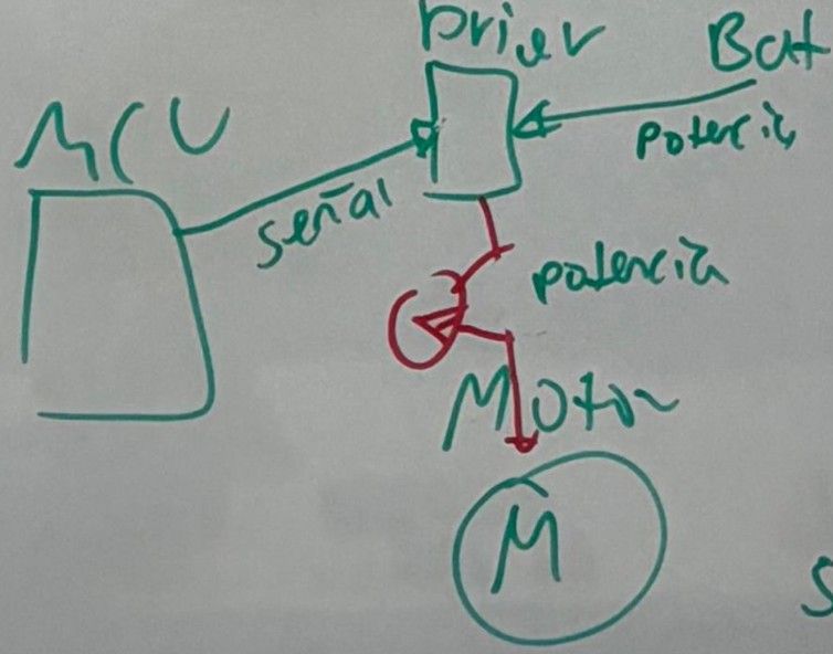
ℹ️ How the System Works
The microcontroller sends PWM control signals to the DRV8833 driver. The driver then determines how much power from the external battery is delivered to the motor. When measuring voltage, the multimeter does not interfere due to its high impedance. When measuring current, the multimeter becomes part of the series circuit path — its resistance is minimal, ensuring accurate readings with negligible impact on the circuit.
⚙️ 3. Motor Control Explanation
Commonly used in CNC machines. They provide high precision and maintain accurate positions during rotation — ideal when exact angular displacement matters.
- Transistors
- MOSFETs
- Solid-state relays (for AC loads)
A circuit made of 4 transistors and 4 diodes that allows changing the direction of the motor by switching the current flow direction. The DRV8833 integrates two full H-bridges on a single chip.
〰️ Speed Control via PWM
Motor speed is controlled using PWM (Pulse Width Modulation). The signal rapidly switches between ON and OFF at a fixed frequency — the ratio of ON time to total period is the duty cycle. The longer the signal stays "on" per cycle, the higher the average voltage delivered to the motor, and therefore the higher the speed and torque.
📊 4. Our Results
The worn 18650 battery could not provide enough voltage at this duty cycle to spin the motor.
OLED Display on My Custom PCB
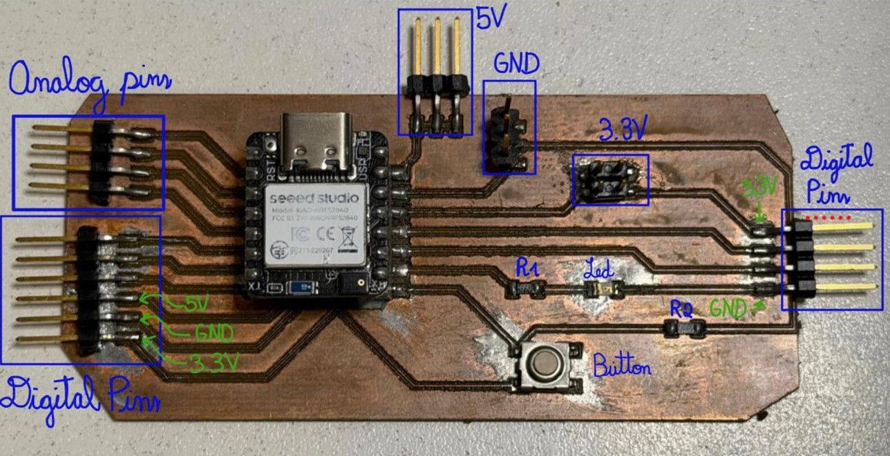
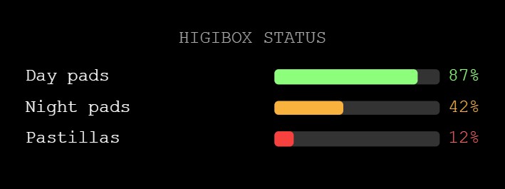
For the individual assignment I used my custom PCB from Week 8 and decided to connect the OLED display that will be part of my final project. The OLED display shows cycle status, product stock levels, reminders, and alerts — helping the user stay informed and supported.
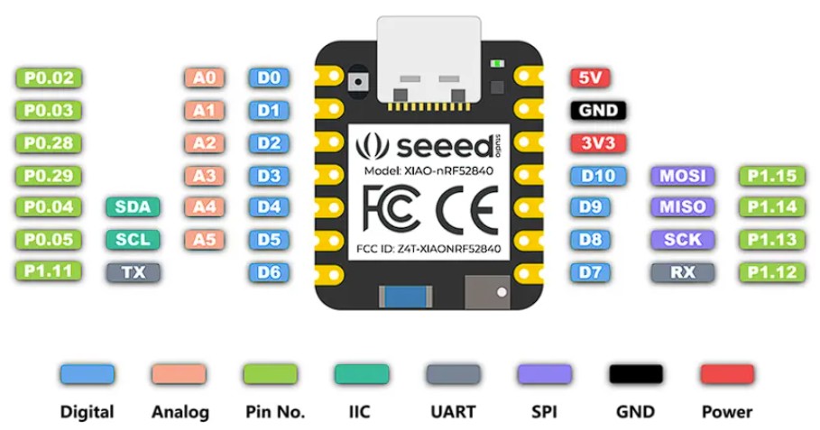
View Week 8 PCBMy board uses the Seeed XIAO nRF52840, which natively supports I2C via its SDA (D4) and SCL (D5) pins. Since these pins were already exposed as accessible headers on my PCB design, I was able to connect the display directly — no additional wiring adaptations needed.
🖥️ OLED Display Overview
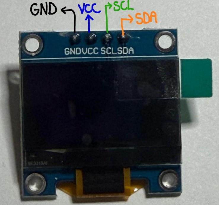
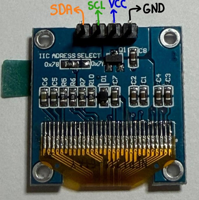
This is a compact monochrome OLED display driven by the SSD1306 controller. It communicates over I2C, meaning it only requires 2 data wires (plus power and ground) — making it very easy to integrate into any project.


Cycles automatically every 5 s · Click a thumbnail to preview
📡 I2C Protocol — SDA & SCL
I2C (Inter-Integrated Circuit) is a serial communication protocol that allows a microcontroller to talk to multiple peripheral devices using only two wires. This is what makes connecting the OLED so straightforward.
This line carries the actual data being transmitted. Both the master (XIAO) and any peripheral device (OLED) share this line. Data is sent bit by bit, and the direction alternates depending on whether the master is writing or reading.
On the XIAO nRF52840 → Pin D4
This line carries the clock signal, generated exclusively by the master device. The clock pulses tell all devices on the bus exactly when to read or write each data bit — ensuring synchronized communication.
On the XIAO nRF52840 → Pin D5
Each I2C device has a unique 7-bit address (the SSD1306 uses 0x3C by default). When the master wants to communicate, it sends the target address on the SDA line, synchronized with SCL clock pulses. Only the device with the matching address responds — which is why you can daisy-chain many devices on the same two wires.
🔌 Connection Table — OLED → My PCB
| OLED Pin | My PCB (Header) | Notes |
|---|---|---|
| VCC | 3.3V (top-right header) | Display runs on 3.3V — safe for XIAO logic |
| GND | GND (top or same header) | Common ground |
| SDA | D4 | I2C data line — native on XIAO nRF52840 |
| SCL | D5 | I2C clock line — native on XIAO nRF52840 |
💻 Code Development & Architecture
The OLED code is structured in 6 steps to create a clean, non-blocking interface:
Import Wire.h (I2C), Adafruit_GFX.h (graphics), and Adafruit_SSD1306.h (OLED driver). These handle all low-level hardware communication.
Adafruit_SSD1306 display(128, 64, &Wire, -1); — This creates a 128×64 pixel display object on the I2C bus.
Store screen index, timing variables (millis-based non-blocking), and inventory counters (stockDayPads, stockNightPads, etc.) as globals so they persist across loop cycles.
Wire.begin(); starts I2C communication. display.begin(0x3C); initializes the SSD1306 at its default address.
Use millis() - lastSwitch >= INTERVAL instead of delay(). This checks elapsed time without blocking, allowing the loop to keep running even if no screen change is due.
Each screenX() function calls display.clearDisplay(), then draws text/graphics using Adafruit GFX methods. display.display() sends the frame buffer to the physical display.
📋 Code Walkthrough Example
Here's how screenWelcome() works:
void screenWelcome() {
  display.clearDisplay();           // Erase previous frame

  display.setTextSize(2);         // Large text (2× normal)
  display.setTextColor(SSD1306_WHITE);
  display.setCursor(20, 10);       // Position (x, y) in pixels
  display.println("HigiBox");

  display.setTextSize(1);         // Normal text
  display.setCursor(35, 35);
  display.println("Welcome!");

  display.drawCircle(64, 50, 3, SSD1306_WHITE);  // Smiley dot
  // display.display() is called in loop(), sends frame to screen
}
🧠 Reflections on the Process
✨ What Worked Well
Using millis() instead of delay() made the screen rotation smooth and responsive. The loop never froze, so future sensor readings won't be delayed.
Separating each screen into its own function made the code readable and easy to debug. Changing one screen doesn't affect others.
Adafruit's GFX library hides all the low-level SSD1306 register details. I could focus on drawing content, not bit-banging I2C.
Because I exposed I2C (SDA/SCL) headers on my Week 8 PCB, connecting the OLED was just 4 wires. No improvisation needed.
⚠️ Challenges Encountered
At first I assumed the OLED address was 0x50. When display.begin(0x50) failed silently (the if statement caught the error), I ran an I2C scanner sketch which discovered the real address: 0x3C.
Forgetting display.display() is easy—the code compiles, but nothing shows on screen. The frame buffer is only sent to the physical display when you explicitly call .display().
When any single I2C wire (VCC, GND, SDA, or SCL) disconnected even partially, the entire display stopped with no error message—just silence. Took ~30 minutes of troubleshooting to trace it. Solution: soldered the final connections and added shrink-wrap cable strain relief. Lesson: Always check hardware first before debugging code.
Centering text and shapes on a 128×64 canvas required guessing pixel coordinates. Eventually I created a mental grid: left edge ≈ x:20, center ≈ x:64, right ≈ x:110.
The small screen forces careful layout. Progress bars, status text, and icons must share 128 pixels width—redesigned multiple times to fit.
🔧 How I Solved These Problems
Solution: I found a free I2C scanner sketch in the Arduino IDE examples. Running it with the OLED connected revealed 0x3C as the active address. Then display.begin(SSD1306_SWITCHCAPVCC, 0x3C) worked immediately.
Solution: I realized display.println() only writes to the frame buffer in RAM—it doesn't send to the physical display. Adding display.display() at the end of loop() fixed it.
Solution: At first I called display.display() inside each screen function, causing repeated refreshes per loop cycle. Moving it to the main loop and adding a millis() guard ensured stable, non-flickering updates every ~100ms.
🔗 The Complete Code — 6 Rotating Screens
The program displays 6 different screens on the OLED, automatically cycling through them every 5 seconds using millis() for non-blocking timing. Each screen corresponds to a feature of my final HigiBox project:
- Welcome message with smiley face
- Stock alert with progress bar
- Low-stock notice message
- Current cycle day tracker
- Motivational reminder with heart
- Full stock status overview
#include <Wire.h>
#include <Adafruit_GFX.h>
#include <Adafruit_SSD1306.h>

#define SCREEN_WIDTH 128
#define SCREEN_HEIGHT 64
#define OLED_RESET -1
Adafruit_SSD1306 display(SCREEN_WIDTH,
  SCREEN_HEIGHT, &Wire, OLED_RESET);

int screenIndex = 0;
unsigned long lastSwitch = 0;
const unsigned long INTERVAL = 5000;

int stockDayPads    = 87;
int stockNightPads  = 42;
int stockPantyLiner = 12;
int cycleDay        = 3;

void setup() {
  Wire.begin();
  if (!display.begin(
    SSD1306_SWITCHCAPVCC, 0x3C))
    while (true);
  display.clearDisplay();
  display.display();
}

void loop() {
  if (millis() - lastSwitch
      >= INTERVAL) {
    lastSwitch = millis();
    screenIndex = (screenIndex+1) % 6;
  }
  switch (screenIndex) {
    case 0: screenWelcome();    break;
    case 1: screenStockAlert(); break;
    case 2: screenMessages();   break;
    case 3: screenCycleDay();   break;
    case 4: screenHydration();  break;
    case 5: screenStockAll();   break;
  }
  display.display();
  delay(100);
}

// Each screen function draws its
// own layout via Adafruit GFX calls
XIAO nRF52840 — Electrical & Power Notes
🔌 Voltage & GPIO Limits
All I/O pins operate at 3.3V. Inputting more than 3.3V can permanently damage the CPU. This applies to all digital and analog pins.
Each GPIO pin is limited to 15 mA maximum. Even a small vibration motor requiring 19 mA cannot be driven directly from a pin.
😴 Deep Sleep
The board consumes only 5 µA in deep sleep mode — excellent for battery-powered wearables and IoT projects where standby efficiency matters.
In practice, with peripherals attached (voltage dividers, sensors), real sleep consumption can rise to 300–600 µA depending on the circuit configuration.
🔋 Battery Management
The board includes a BQ25101 chip that supports battery charge management, compatible with a 3.7V Lithium-Ion battery — ideal for portable and wearable projects.
- CPU: ARM Cortex-M4 @ 64 MHz
- GPIO: 11 digital (all PWM), 6 ADC
- Wireless: Bluetooth 5.0, NFC, ZigBee
- Logic: 3.3V strictly
🏎️ Motor Driver Recommendations
Since GPIO pins are limited to 15 mA, to drive motors you must use a dedicated driver. Common options compatible with the XIAO's 3.3V logic:
| Driver | Max Motor Voltage | Max Current | Notes |
|---|---|---|---|
| DRV8833 | 10V | 1.5A per channel | Great for small DC motors — used this week |
| L9110S | 12V | 800 mA | Cheap and easy to use |
| TB6612FNG | 15V | 1.2A per channel | Very popular, 3.3V logic friendly |
| MOSFET (e.g. 2N7000) | Depends on FET | Depends on FET | For simple on/off motor control |
✅ Final Project To-Do
- Use an external power source for the motor — the XIAO cannot supply enough current (risk of damage).
- Calculate the required voltage for the system. If sources are connected in series, voltages add up.
- For each duty cycle, record: Voltage (V), Current (I), and calculate Power (P = V × I).