Assignments
Assignment
Group assignment
- Do your lab's safety training.
- Test runout, alignment, fixturing, speeds, feeds, materials, and toolpaths for your machine.
Individual assignment
- Make (design + mill + assemble) something big (~meter-scale).
- Extra credit: Don't use fasteners or glue.
- Extra credit: Include curved surfaces.
Group Assignment Summary
In the group assignment, I explored how to operate the MultiCam 3000 CNC machine. We tested several parameters including runout, alignment, fixturing methods, speeds, feeds, materials, and toolpaths. Through these tests, I was able to observe how each parameter affects the machining process and compare different configurations to determine which settings worked best for the material and cutting conditions.
🔗 For more detail on the Group Assignment, visit the official Fab Academy page:
Visit Fab Academy ULima →Lab Safety Training
Lab safety training is important because it teaches how to operate machines safely, understand potential risks, and prevent accidents in the lab, especially when working with high-speed CNC machines.


Machine Specifications
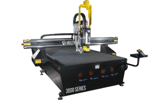
The CNC machine used for this assignment was the MultiCam 3000 Series CNC Router. This machine allows large-scale machining of materials such as plywood, MDF, plastics and composite materials using computer-controlled toolpaths.
- Machine Model: MultiCam 3000
- Number of Axes: 3-axis (X, Y, Z)
- Working Area: approximately 1270 mm × 2540 mm
- Drive System: Rack and pinion (X,Y) and ball screw (Z)
- Spindle Speed: up to 24,000 RPM
- Tool Type: End mill router bit
- Dust Collection: External dust extraction system
- Work Surface: Sacrificial bed
Cutting Parameters
For machining the plywood sheet (18 mm thickness), the following cutting parameters were used. These values were selected to achieve stable cutting and avoid burning the material.
Cutting parameters — 18mm plywood
Tabs / Bridges Test
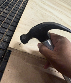
One of the important tests performed was the use of tabs (bridges). Tabs are small connections that keep the piece attached to the material sheet during the machining process. Their purpose is to prevent the pieces from moving or being displaced when the final contour is cut. After machining, the tabs are manually removed during the finishing stage.
Example of bridges (tabs) used to hold the pieces during machining.
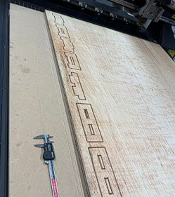
The tabs prevent the pieces from moving while the CNC is cutting the contour.
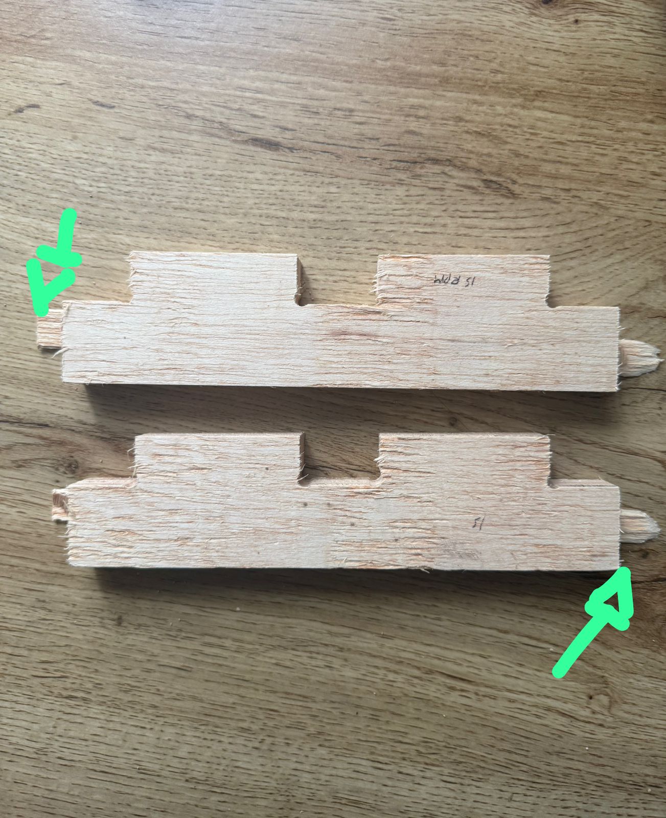
Press-fit Tolerance Test
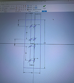
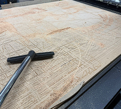
To determine the correct press-fit tolerance, several test slots were designed before machining the final model. The tests started from 18.0 mm and increased gradually up to 18.5 mm, increasing by 0.1 mm each time. This allowed us to observe how tight or loose the joint would be when assembling the parts.
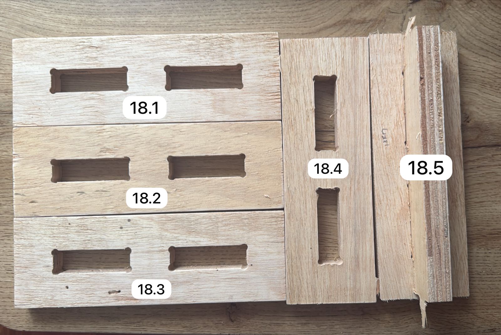
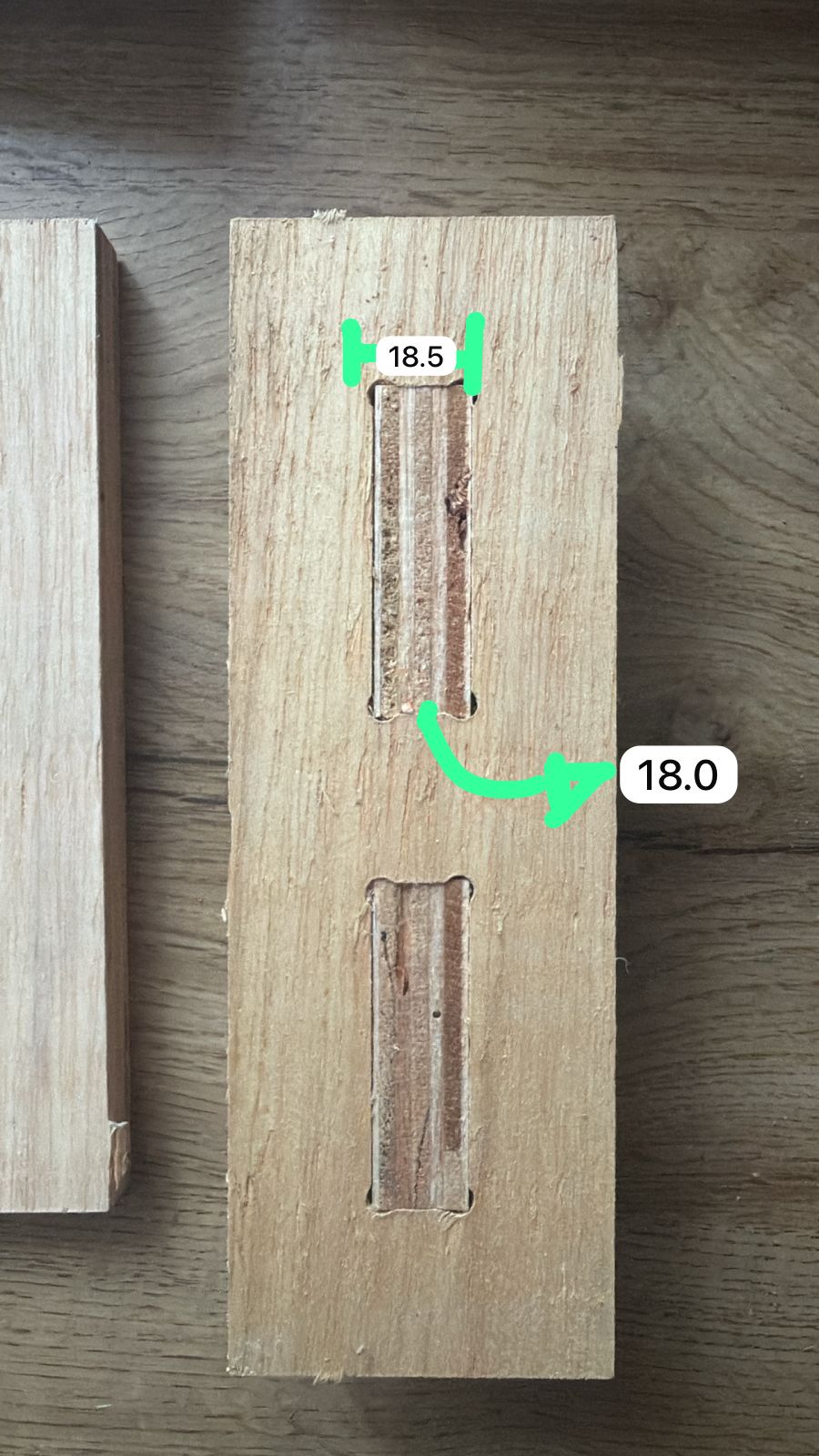
Press-fit tolerance tests to determine the best slot dimension for 18 mm plywood.
Individual Assignment
Introduction
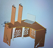
For the individual assignment, the objective was to design, machine, and assemble a large-scale object using a CNC machine. The project focused on designing a desk for my sister, since she had limited space available for her study area. Based on her needs, I designed a custom desk structure that could fit her workspace while remaining stable using press-fit joints without screws or glue.
Design Concept
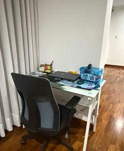
The available workspace was analyzed to understand the dimensions and limitations of the area.
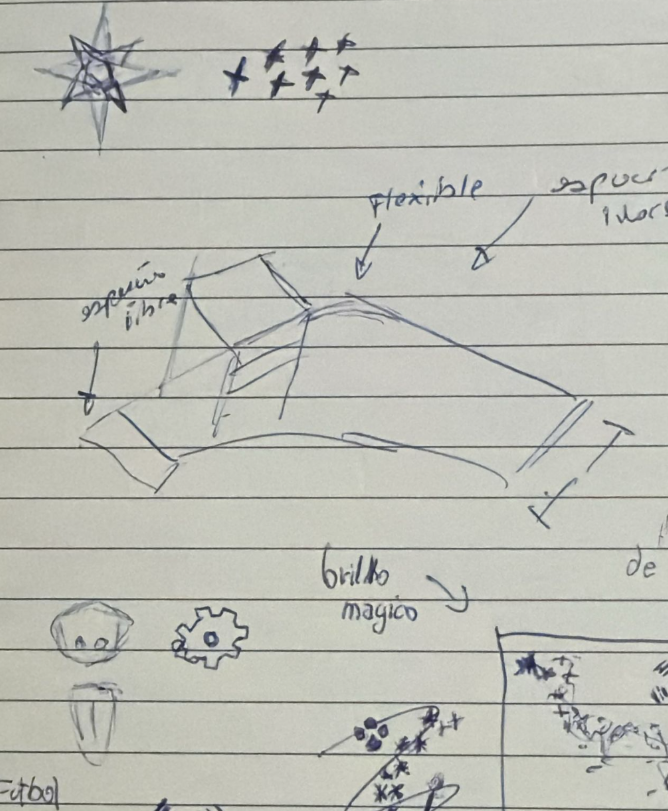
Based on these requirements, the desk structure was designed in CAD considering assembly and stability.
Material Measurement
The plywood thickness was measured to determine the correct slot size.
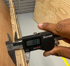
A tolerance value was added to the design to ensure the parts could fit correctly.
Tolerance Test
A small press-fit test was machined to verify the tolerance.
After confirming the tolerance, it was applied to the full design before generating toolpaths.
CAM Setup and G-code Generation
With the design ready, the next step was to set up the toolpaths in the CAM software (EnRoute) and generate the G-code files to send to the MultiCam 3000. The process goes from importing the DXF file all the way to sending the code to the machine.

Importing the DXF into EnRoute
We exported the design as a DXF from Autodesk Inventor and imported it into the CAM software (EnRoute). The red rectangle represents the available material area, the work table of the CNC machine. The design pieces are positioned inside this boundary so they all fit within the sheet.

Positioning all pieces
All the desk parts were arranged within the available material area. Some pieces extended outside the first sheet so a second sheet was needed. The red boundary shows the exact work area of the CNC table that can actually be cut.
After positioning the parts, we selected all the profiles and opened the Router Offset tool. This is where the toolpath parameters are defined for the CNC machine.

Router offset tool
Selecting the Router Offset tool and choosing the 6mm end mill (Fresa de 6mm), type Basto, at a depth of 10.5 mm for the first pass. Tabs (Puentes) are enabled with a 2mm bridge length to keep parts attached during cutting.

Final cut depth
The same tool at full depth of 18.5 mm (slightly deeper than the 18 mm plywood to cut all the way through). Externo macho (external offset) is checked so the tool path goes around the outside of each profile.

Parameters — collapsed view
Clicking Edit inside the Router Offset tool opens the cutting parameters dialog. Here you can see the main categories: Profundidades (depths), Pases (passes), Anchuras (widths), Alimentaciones y Velocidades (feed and speeds), Dirección (direction).

Parameters — values expanded
With the tree expanded you can see the actual values: final depth 18.5 mm, 3 passes, 6.17 mm per pass, feed rate 120 mm/min. After reviewing these values we click Accept.
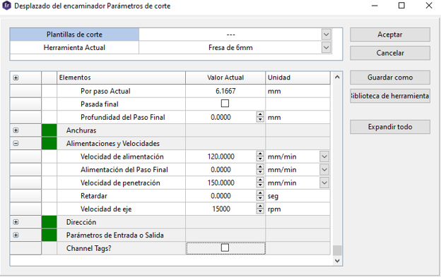
Feed rates and spindle speed
Scrolling down in the same parameters dialog shows the speed values: feed rate 120 mm/min, plunge rate 150 mm/min, and spindle speed 15,000 RPM. These are the actual values that get written into the G-code file.
CAM parameters confirmed in EnRoute
Generated toolpath
After clicking Accept the toolpath is generated. The blue lines are the internal cuts (slots and holes) and the red lines are the external contour cuts. The green dots mark the entry points of the tool. You can see clearly how the tabs appear as small breaks along the outer contour to keep the piece attached to the sheet.

Saving the G-code
To send the code to the machine we press the G1 button in the toolbar. This generates the G-code file and we save it with the name "corte1". Each sheet or operation gets its own numbered file (corte1, corte2, etc.) so they stay organized.

CODIGOS NC folder
The exported CNC files are saved in a dedicated folder called "CODIGOS NC" on the desktop. You can see all the cut files: corte1, corte2, corte3... up to corte11, plus other files like holes and circulo. Each one is a separate CNC file (.CNC or .ROU).
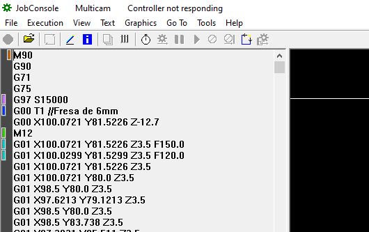
G-code in JobConsole
The generated G-code file is opened in JobConsole (the MultiCam machine controller software). You can see the actual instructions: G97 S15000 sets the spindle speed, G00 T1 calls the 6mm end mill, then the G01 movement commands move the tool along X, Y, Z at the configured feed rates.
JobConsole also shows a graphic preview of the toolpath before sending it to the machine. This is the last check before pressing start.
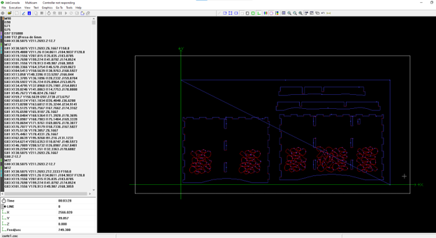
Graphic preview — sheet 1
First sheet showing the full desk top and side panels. The graphic view lets you verify all contours are correct before cutting.
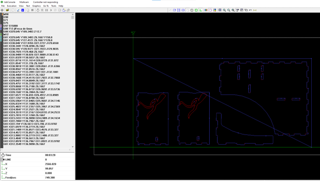
Graphic preview — sheet 2
Second sheet with the remaining structural pieces. Each file corresponds to one sheet of plywood.
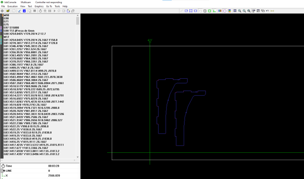
Graphic preview — sheet 3
Third sheet with the last pieces. Once all previews look correct, each file is sent to the MultiCam one by one to start the actual cutting process.
M90
G90
G71
G75
G97 S15000
G00 T1 //Fresa de 6mm
G00 X100.0721 Y81.5226 Z-12.7
M12
G01 X100.0721 Y81.5226 Z3.5 F150.0
G01 X100.0299 Y81.5299 Z3.5 F120.0
G01 X100.0721 Y81.5226 Z3.5
G01 X100.0721 Y80.0 Z3.5
G01 X98.5 Y80.0 Z3.5
...
CNC Machining and Assembly
CAM and CNC Preparation
The CNC bed was cleaned with a vacuum before machining.
Material Preparation
Before starting the machining process, the 18 mm plywood (triplay) was placed on the CNC sacrificial bed to avoid damaging the machine table during cutting.
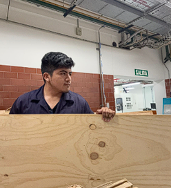
The plywood sheet was prepared and positioned on the CNC machine bed.
Placed on the sacrificial bed to protect the machine table.
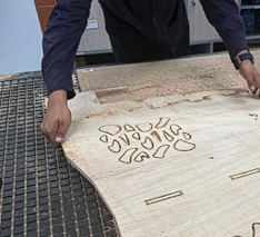
CNC Machining
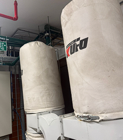
The dust extraction system was activated to remove wood chips during machining.
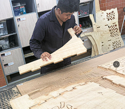
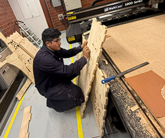
After machining, the parts were removed from the plywood sheet.
Finishing
The edges were sanded to remove splinters and improve the finish.
A file was used to refine some slots for better fitting.
Final Assembly
All the pieces were organized before starting the assembly.
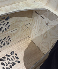
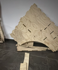
The structure was assembled using press-fit joints.
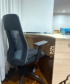
Final desk assembled and ready to use.
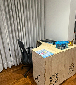
The desk fits perfectly in the available workspace.
Thanks to the 0.5 mm tolerance used in the slots, the parts entered with pressure and the desk structure became stable without screws or glue.
Project Downloads
Download all files