Assignments
Assignments
Group assignment:
- Test the design rules for your 3D printer(s).
Individual assignment:
- Design, document, and 3D print an object that could not be made subtractively (small, few cm³, limited by printer time).
- 3D scan an object (and optionally print it).
Week Summary
During this week of Fab Academy, I tested the different 3D printers available in the lab to better understand their design rules, material behavior, and limitations. This helped me determine which machine is most appropriate for specific applications. Afterward, I printed a personal design in PLA to evaluate print quality and performance, and I also tested the 3D scanner by digitizing a physical object to analyze its resolution and detail capture.
Contribution Group Assignment
🔗 If you want to explore the Group Assignment in more detail, you can visit the official Fab Academy page:
Visit Fab Academy ULima →In the group assignment, I contributed by researching and comparing two different 3D printing technologies: FDM and MSLA. For FDM, we worked with a Markforged printer to analyze design rules, tolerances, and material behavior under fused deposition modeling. For MSLA, we explored resin-based printing using a Phrozen printer, focusing on surface quality, detail resolution, and dimensional accuracy. This comparison allowed us to better understand the advantages, limitations, and applications of both technologies.
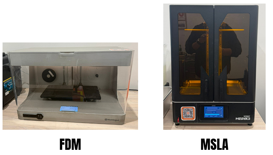
Markforged Mark Two (Gen 2)
The Mark Two is a professional desktop 3D printer built to produce strong, functional, and structural parts. By combining engineering-grade thermoplastics with continuous fiber reinforcement, it enables lightweight components with high stiffness for real-world use.
Technology (FDM)
FDM (Fused Deposition Modeling) is one of the most common 3D printing technologies. It builds parts by melting a thermoplastic filament and depositing it through a heated nozzle layer by layer. As each layer cools, it solidifies and bonds to the previous one, gradually forming the final object.
Markforged Mark Two — Printing Workflow (Eiger)
To print my part on the Markforged Mark Two, I followed a simple workflow inside the Eiger software. First, I
uploaded my STL file and checked how it looked on the virtual build plate, confirming the scale and orientation before moving forward.
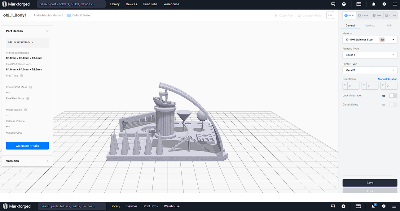
Next, I selected the correct printer profile and confirmed the materials available for the job (plastic and fiber) so the platform could calculate
the build correctly. Then I reviewed the build details such as estimated print time and material usage to make sure the print was feasible.
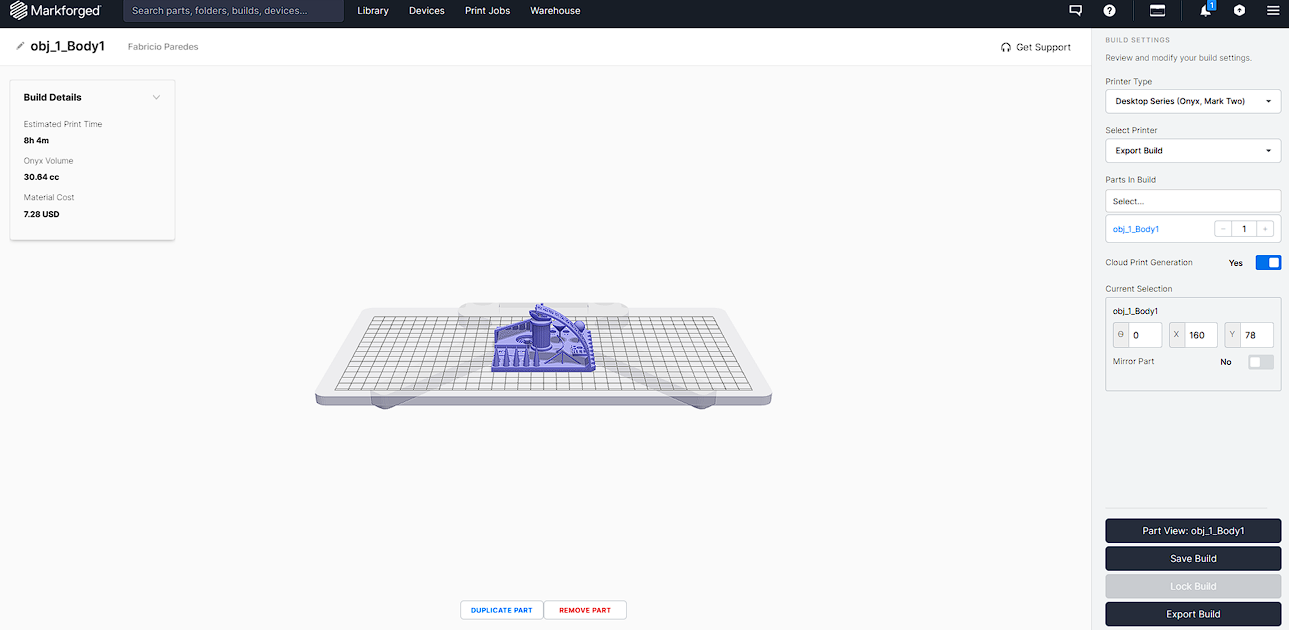
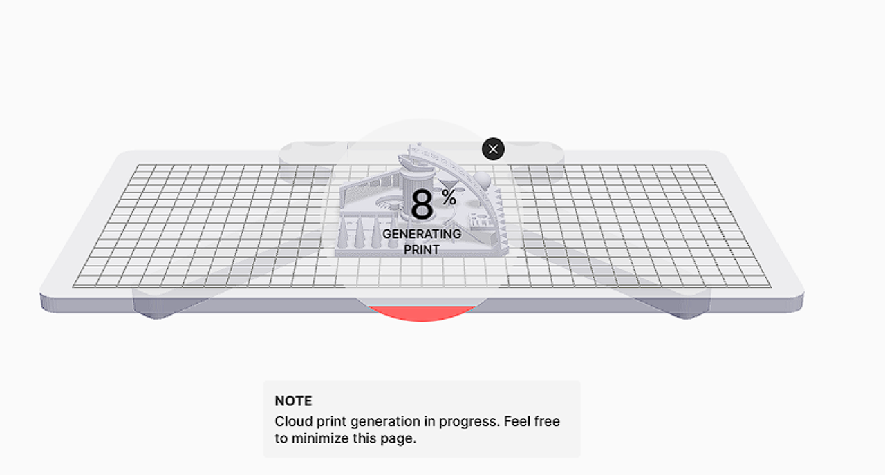
After validating the setup, I exported the build and Eiger started generating the print in the cloud, showing a progress percentage while preparing
the final print file.
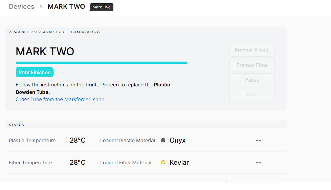
Finally, once the file was ready, I sent the job to the printer and monitored it from the Devices section until the system reported Print Finished.
Testing
Selected Fiber
Selected Plastic
Click a material
Choose a fiber (top) or plastic (bottom) to load its image and see a short description.
FDM Test Results & Observations
Summary-Markforged Mark Two (FDM)
The Markforged Mark Two showed stable and reliable performance during the test prints. The enclosed chamber helped maintain consistent temperature, improving layer adhesion and reducing warping. Dimensional features were generally accurate, although fine details, overhangs above 40°, and bridging areas required optimized settings. Overall, the machine allowed a clear understanding of how wall thickness, shells, layer height, and cooling affect final print quality.
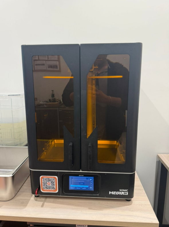
Phrozen Sonic Mega 8K (Resin / MSLA)
The Phrozen Sonic Mega 8K is a large-format resin 3D printer designed for high-detail prints. Using UV light to cure liquid photopolymer resin, it builds objects layer by layer, achieving smooth surfaces, sharp edges, and excellent micro-detail reproduction.
Technology (MSLA)
MSLA (Masked Stereolithography) is a resin-based 3D printing technology that solidifies liquid photopolymer resin using ultraviolet (UV) light and a monochrome LCD screen. Unlike FDM printers that extrude filament, MSLA systems cure entire resin layers simultaneously through an LCD masking system inside a resin vat.
Compared to traditional SLA systems that use a laser to cure resin point by point, MSLA technology provides faster printing speeds while maintaining high resolution and smooth surface quality.
After printing, parts must be washed to remove excess resin and then UV cured to achieve their final mechanical properties.
Preparing the Resin Print (CHITUBOX)
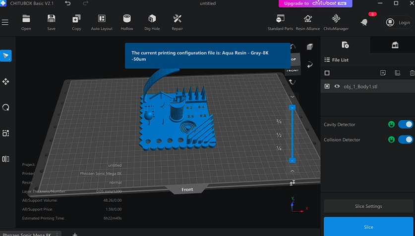
To prepare the MSLA test print, I worked inside CHITUBOX and followed a simple workflow: select the correct machine, choose the resin profile, place the model on the build plate, review the basic print settings, and finally slice the file to generate the print-ready output and check the estimated consumption/time.
-
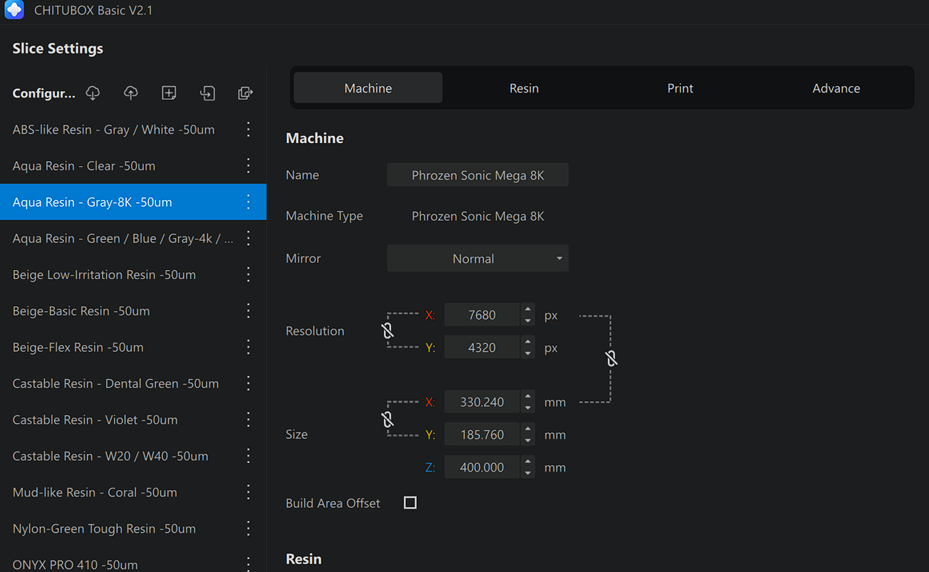
I selected the printer profile.
I confirmed the machine as Phrozen Sonic Mega 8K so the software used the correct build volume and screen resolution. -
I chose the resin configuration.
From the resin list, I selected Aqua Resin - Gray-8K (50µm). This ensures the slicer uses exposure values appropriate for that resin and layer height. -
I imported the model (STL) and placed it on the plate.
After loading the file, I checked that the model was fully inside the printable area and positioned it from the front view to clearly see the main features of the test piece. -
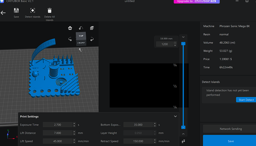
I reviewed the printing parameters.
Before slicing, I verified the key settings for this profile, such as:- Layer height: 0.050 mm (50µm)
- Exposure time: 2.7 s
- Bottom exposure: 35 s
- Lift distance: 7 mm
- Lift speed: 45 mm/min
- Retract speed: 150 mm/min
-
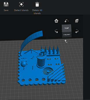
I checked islands (optional check).
The software shows an option to run Detect Islands. This is useful to identify areas that might print “in the air” without support, but it had not been run yet at that moment. -
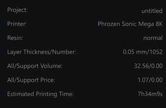
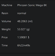
I sliced the model and reviewed the estimate.
After slicing, I checked the summary to understand the print requirements. The estimate showed approximately:- Print time: ~6h 22m
- Resin volume: ~48 ml
- Weight: ~53 g
- Cost estimate: ~1.59
Testing
Selected Resin
Selected Process
Click an option
Choose a resin (top) or a post-processing step (bottom) to load an image and read a short description.
Learnings from the Resin Group Assignment
Summary – Phorzen Sonic
The Phorzen Sonic demonstrated high precision and excellent surface quality during testing. The liquid resin and UV curing process allowed for smoother finishes and better detail definition compared to FDM. Dimensional accuracy was generally very good, especially for small features and curved surfaces. However, proper support placement was critical, and post-processing steps such as washing and UV curing were necessary to achieve full mechanical strength. Additionally, removing supports required care to avoid damaging fine or thin features.
Individual Assignment
Design of a Part Not Manufacturable by Subtractive Methods
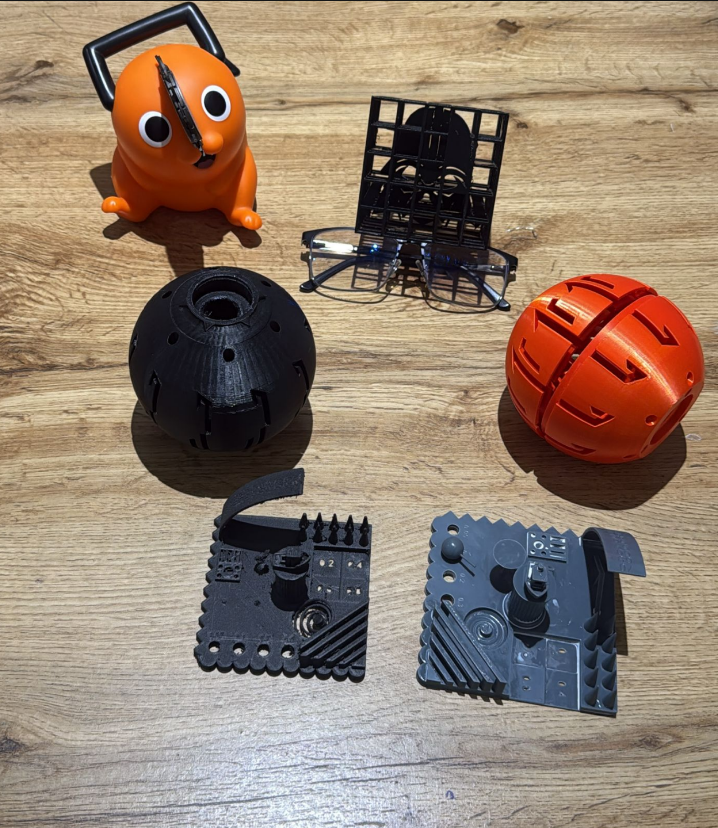
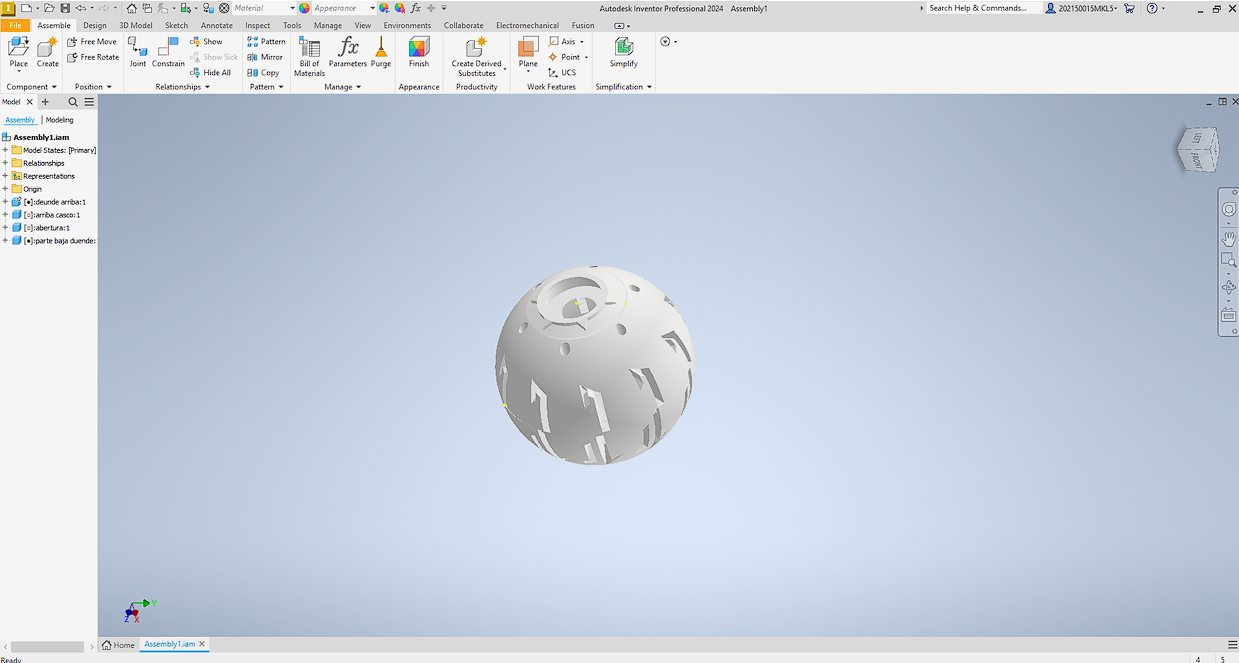
The objective of this assignment was to design a part that could not be manufactured using traditional subtractive processes such as CNC machining or laser cutting. I designed a hollow sphere with internal cavities intended to house electronic components. The geometry includes enclosed internal features that cannot be accessed from the outside, making it impractical to fabricate using conventional machining methods.
CAD Design (Autodesk Inventor)
The sphere was modeled with an internal volume planned for future integration of electronics, keeping the external shell closed while incorporating internal geometry.
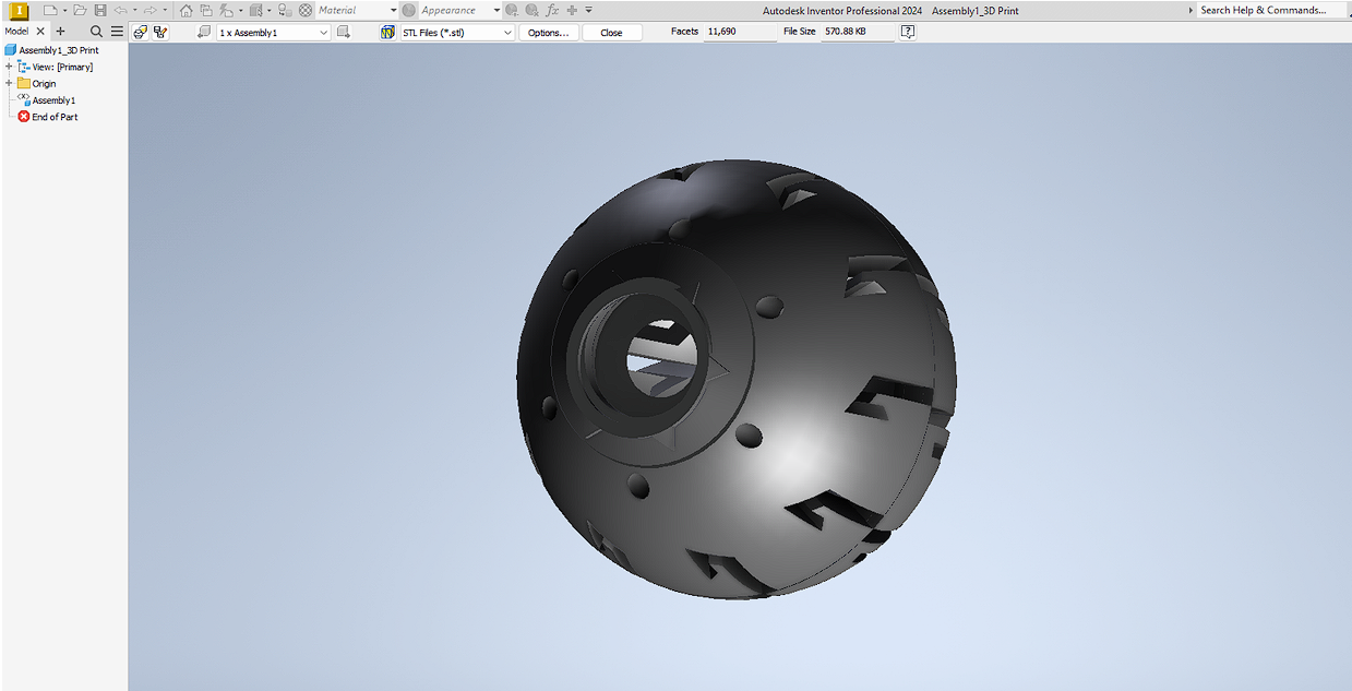
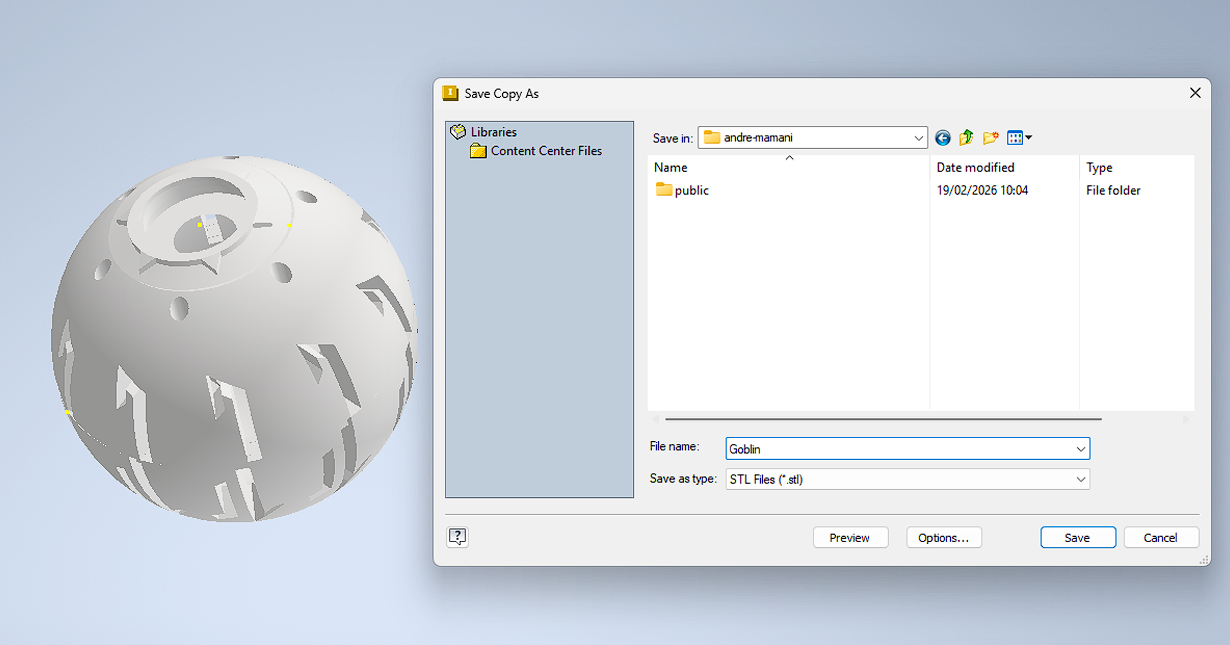
Exporting the Model for 3D Printing
After completing the CAD design, the model was exported as an STL file to prepare it for slicing.
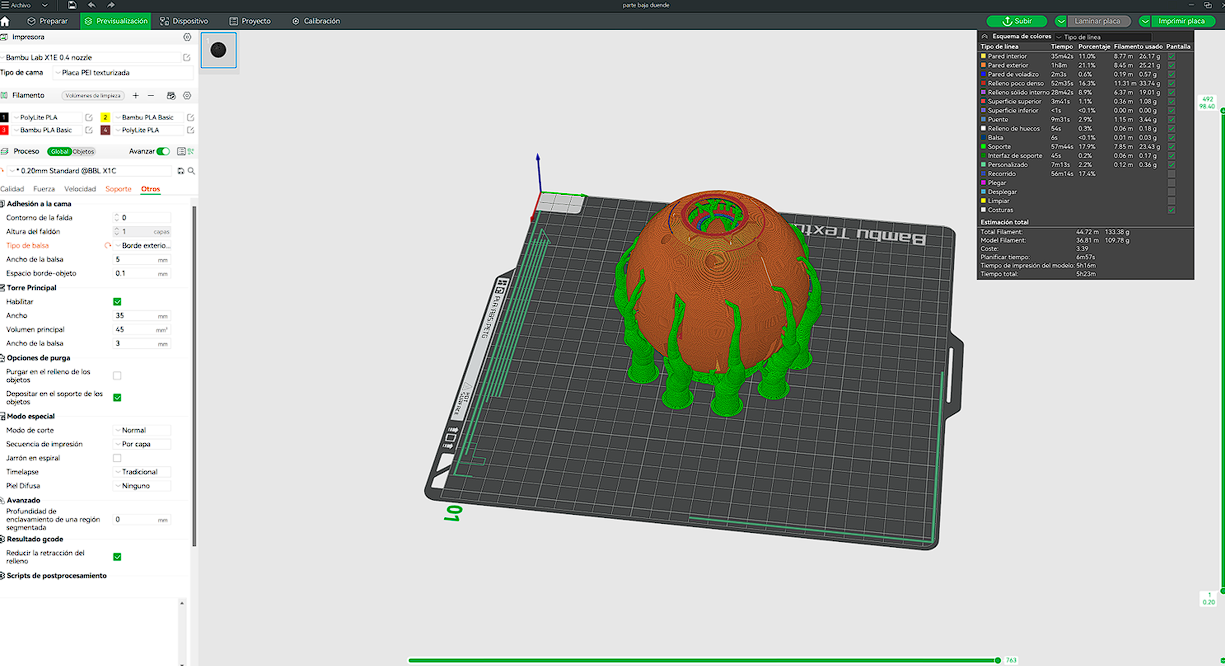
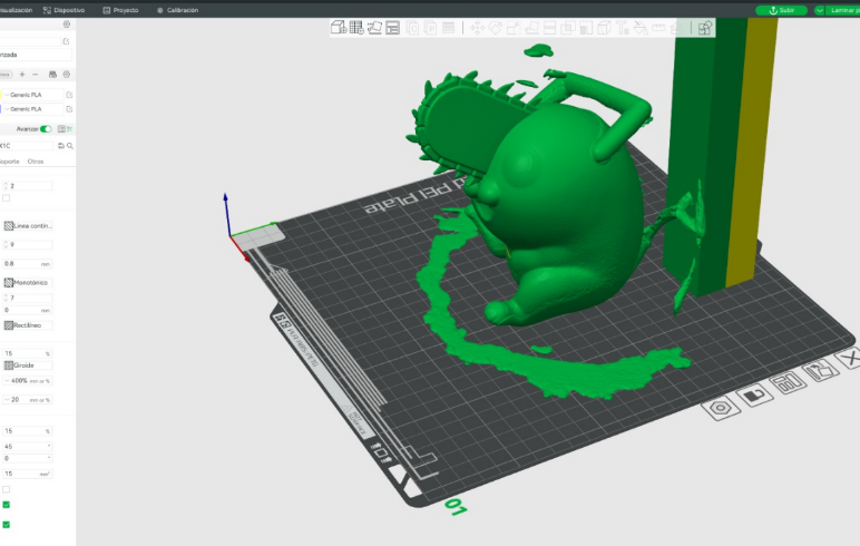
Slicing and Support Generation
The STL file was imported into the slicer and supports were generated due to overhangs and internal features. The following parameters were used:
- Material: PLA
- Nozzle: 0.4 mm
- Layer Height: 0.2 mm
- Infill: 15%
- Supports: Enabled
- Support Angle Threshold: 30°
- Build Plate: Textured PEI
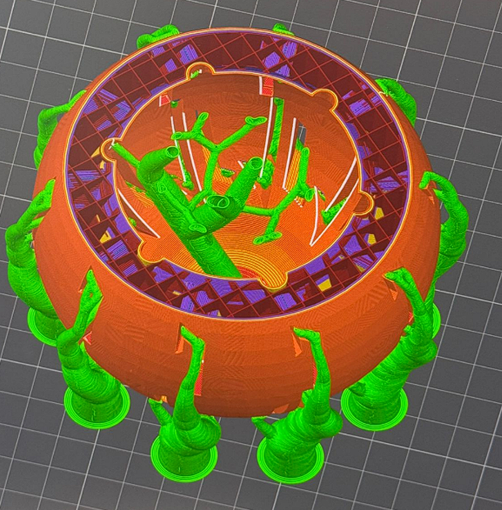
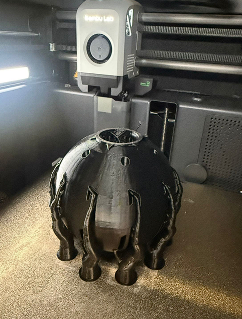
Printing Process
After slicing, the file was sent to the printer and the part was printed using the selected settings. For this test, I decided to use a dual-material configuration in order to experiment with PVA (Polyvinyl Alcohol), a water-soluble filament commonly used for support structures. This required loading two filaments in the printer: PLA as the main structural material and PVA as the support material. The idea was to facilitate post-processing, since the supports made of PVA can dissolve in water, reducing the risk of damaging delicate features during removal.
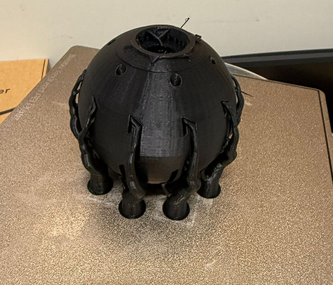
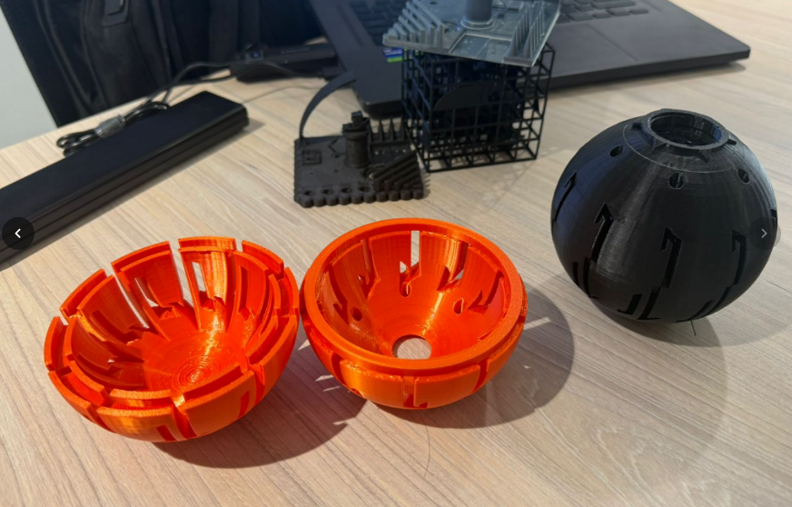
Final Printed Result
After printing, the supports were removed manually. Some surface marks from support contact were visible, which is expected for complex enclosed geometries.
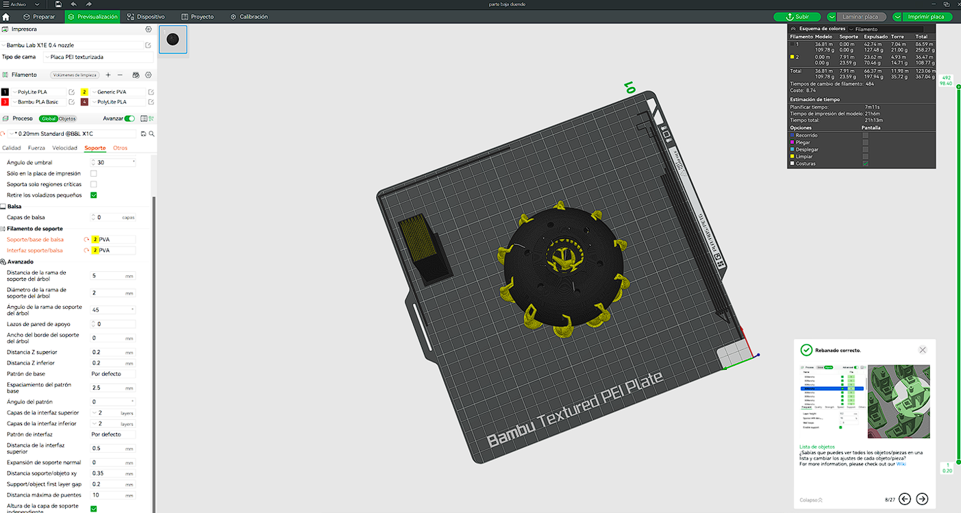
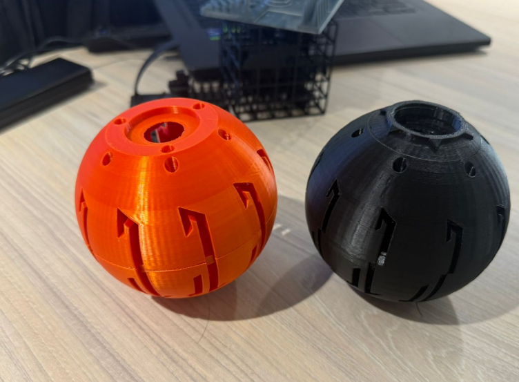
Design Improvement – Two-Part Assembly for Internal Mechanism
In this stage, the design was modified by dividing the sphere into two main parts. The purpose of this change was to allow the integration of an internal mechanism (the green internal structure planned as the pump system). By separating the body, it became possible to access the internal cavity and properly position future components.
In addition, since both parts were designed as a press-fit assembly, a tolerance of approximately 0.5 mm on each wall was intentionally added between the two pieces. This clearance allowed the parts to fit together more easily without requiring excessive force, while still maintaining a stable and functional connection.
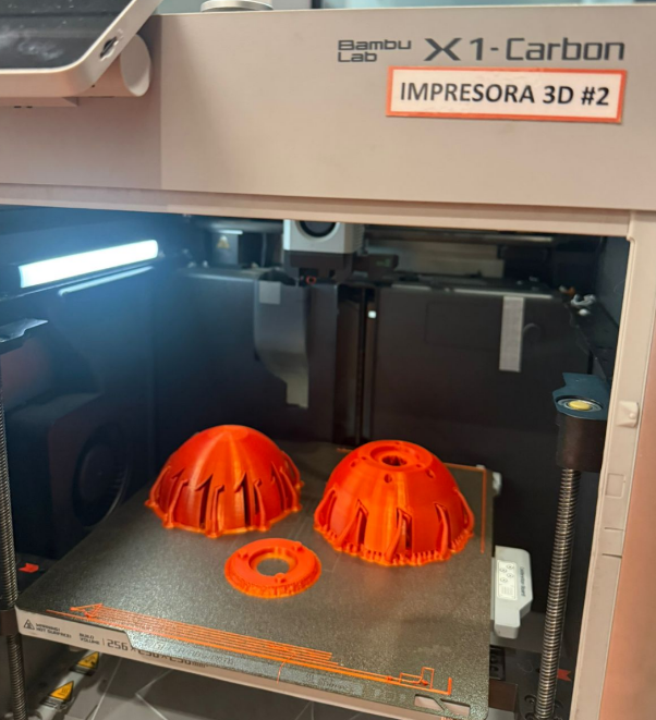
For this iteration, only the base structure was fabricated using the Bambu Lab X1-Carbon printer. The part was printed in PLA, focusing on validating dimensional accuracy, fit between both halves, and the alignment of internal features. This step allowed verification of the assembly behavior before continuing with the fabrication of the complete internal mechanism.
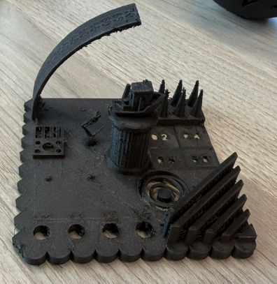
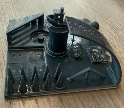
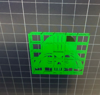
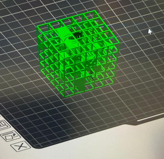
Support Strategy Test
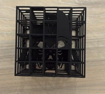
In this test, I experimented with a dense external support structure by enclosing the model inside a cubic grid. The intention was to guarantee full structural stability during printing, especially considering the complex internal geometry and multiple overhangs.
For this experiment, I used the model available on Thingiverse . One of the most interesting aspects of this design is that it is very easy to use, since the platform only requires uploading an image for each face of the cube. After assigning the images, the system automatically generates the final 3D model ready for export and printing.
The slicer generated a large amount of supports surrounding the entire model. While this ensured that overhangs were fully supported, it significantly increased material usage and print time. The support density was high, which created a rigid external cage.
After printing, the removal process became challenging. Because too many supports were generated, access to internal and delicate areas was limited. The dense grid structure required significant force to detach, increasing the risk of damaging fine features.
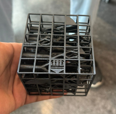
Final Result and Observations
Although the print completed successfully, the excessive support structure made post-processing difficult. Some delicate internal details were partially affected during support removal. This test demonstrated that while increasing support density improves stability during printing, it can negatively impact post-processing and surface quality. A more optimized support strategy with controlled density and selective placement would provide a better balance between structural reliability and ease of removal.
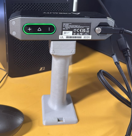
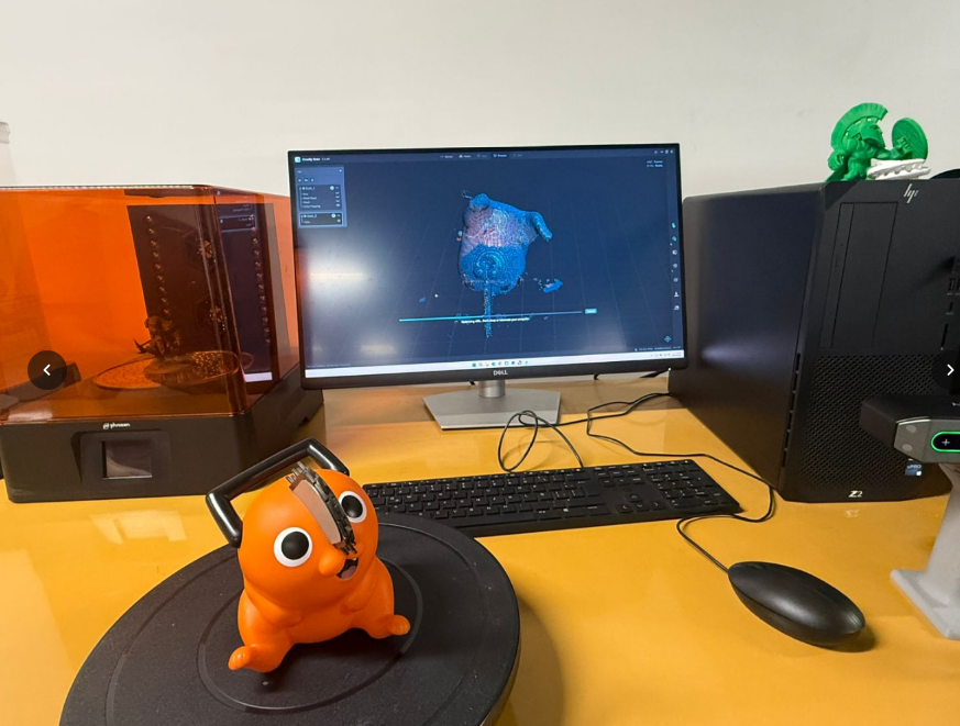
3D scanning – CR Scan 060
Finally, I scanned a physical object using the CR Scan 060. This device is a handheld 3D scanner based on structured light technology. It works by projecting light patterns onto the object’s surface and capturing how those patterns deform using integrated cameras. From this information, the scanner calculates the 3D geometry through optical triangulation, producing a point cloud that can later be converted into a 3D mesh.
The scanner includes RGB cameras for texture capture and depth sensing to reconstruct the object’s shape with good accuracy. It is especially useful to digitize physical parts and convert them into editable models for CAD or mesh workflows.
3D Scanning Process
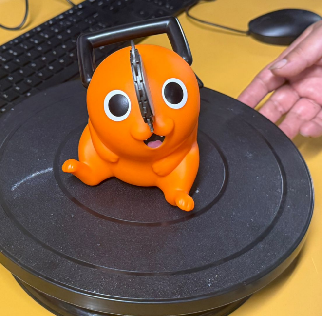
First, I selected the object to be scanned. The chosen object was a small figurine placed on a rotating platform to allow a full 360° capture. Proper positioning was important to ensure visibility of all external surfaces.
The scanning process began by capturing one side of the object. The scanner progressively collected point cloud data while the platform rotated. At this stage, only partial geometry was visible in the software.
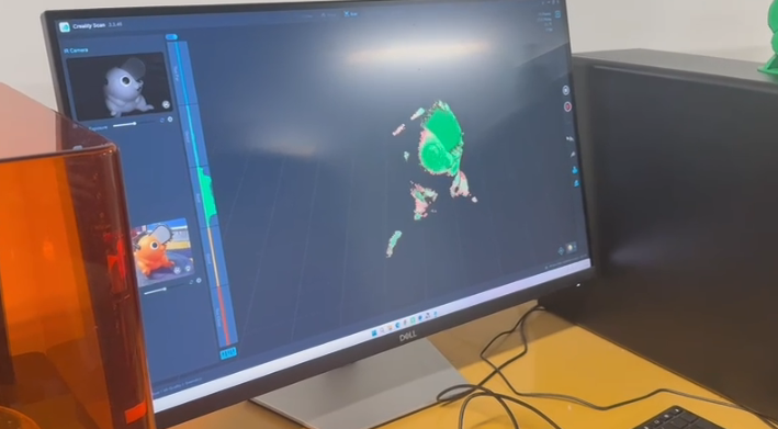
Then, the object was scanned from another angle to capture the missing areas. Multiple scans were required to cover hidden geometries and lower sections that were not visible during the first pass.
After obtaining separate scans, the software displayed multiple point clouds. These datasets needed to be aligned in order to reconstruct the complete geometry.
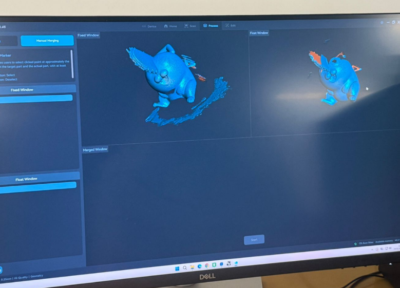
To merge the scans, reference points were manually selected on matching areas of each model. These markers allowed the system to calculate spatial alignment and accurately combine both datasets into a single unified mesh. Finally, the merged model was processed to generate a complete 3D mesh. Some noise and small artifacts were still visible and required cleanup, but the overall geometry of the object was successfully reconstructed.
Finally, the merged model was processed to generate a complete 3D mesh. Some noise and small artifacts were still visible and required cleanup, but the overall geometry of the object was successfully reconstructed.
Project Downloads
Download all files related to the cube generation and STL models: