Assignments
Week 4 – Embedded Programming
Assignment
Individual assignment
- Browse through the data sheet for a microcontroller.
- Write and test a program for an embedded system using a microcontroller to interact (with input and/or output devices) and communicate (with wired or wireless connections).
- Extra credit: assemble the system
- Extra credit: try different languages and/or development environments
Group assignment
- Demonstrate and compare the toolchains and development workflows for available embedded architectures.
Contribution to the Group Assignment
🔗 If you want to explore the Group Assignment in more detail, you can visit the official Fab Academy page:
Visit Fab Academy ULima →During the group assignment, my contribution focused on the technical research and structured comparison of different microcontroller boards. I reviewed the official datasheets of the following boards:
- Arduino UNO R3
- ESP32 (WROOM)
- Raspberry Pi Pico 2 W
- Arduino Nano
From each datasheet, I extracted and analyzed key technical specifications such as processor architecture (8-bit vs 32-bit), clock frequency, Flash memory, SRAM, operating voltage, number of digital and analog I/O pins, communication protocols (UART, SPI, I2C), and wireless connectivity features.
Additionally, I developed a comparative table that organized these technical parameters in a clear and structured format. The comparison criteria were selected based on embedded system requirements, including processing capability, memory constraints, communication needs, and hardware flexibility.
📝 Group Assignment Reflection — What I Learned
Working through the group comparison taught me several things I would not have noticed by just using the boards:
- Datasheet literacy matters. Numbers like "32 kB Flash" and "2 kB SRAM" look small until you try to fit a real program into them — the ATmega328P's 2 kB SRAM is a hard ceiling that forces you to think about every variable you declare.
- Architecture generation gap. Moving from 8-bit AVR (ATmega328P) to 32-bit ARM (RP2350, nRF52840) is not just a speed upgrade; it changes the peripheral model, the interrupt system, and even how you write time-critical code.
- Wireless is not free. The ESP32 and Pico 2 W both advertise WiFi/BLE, but the antenna placement, co-existence with GPIO, and power budget differ significantly — details only visible in the datasheet's electrical characteristics section.
- Voltage levels are a real integration risk. The Seeed XIAO nRF52840 is 3.3 V logic; the Arduino UNO R3 is 5 V. Mixing them without a level-shifter can destroy the 3.3 V board — a fact buried deep in the "Absolute Maximum Ratings" table.
- The group page currently has no documentation. I will coordinate with lab mates to add toolchain screenshots, environment setup steps, and workflow diagrams there.
Development Board and Microcontroller
What is a Development Board?
A development board is a complete electronic platform designed to help us prototype, test, and program embedded systems easily. It includes a microcontroller as its main brain, along with additional components such as voltage regulators, USB interface, communication ports, buttons, LEDs, and sometimes wireless modules.
In simple words, the development board is the physical platform that allows us to interact with the microcontroller safely and efficiently without building the entire circuit from scratch.
What is a Microcontroller?
A microcontroller is a small integrated circuit that acts as the brain of an embedded system. It contains a processor (CPU), memory, input/output pins, and communication interfaces all inside a single chip. It executes programs written by the user to control sensors, motors, LEDs, displays, and communication systems.
Every development board includes at least one microcontroller. The board provides the supporting electronics, while the microcontroller performs the actual computation and control tasks.
Click a board to read its datasheet analysis
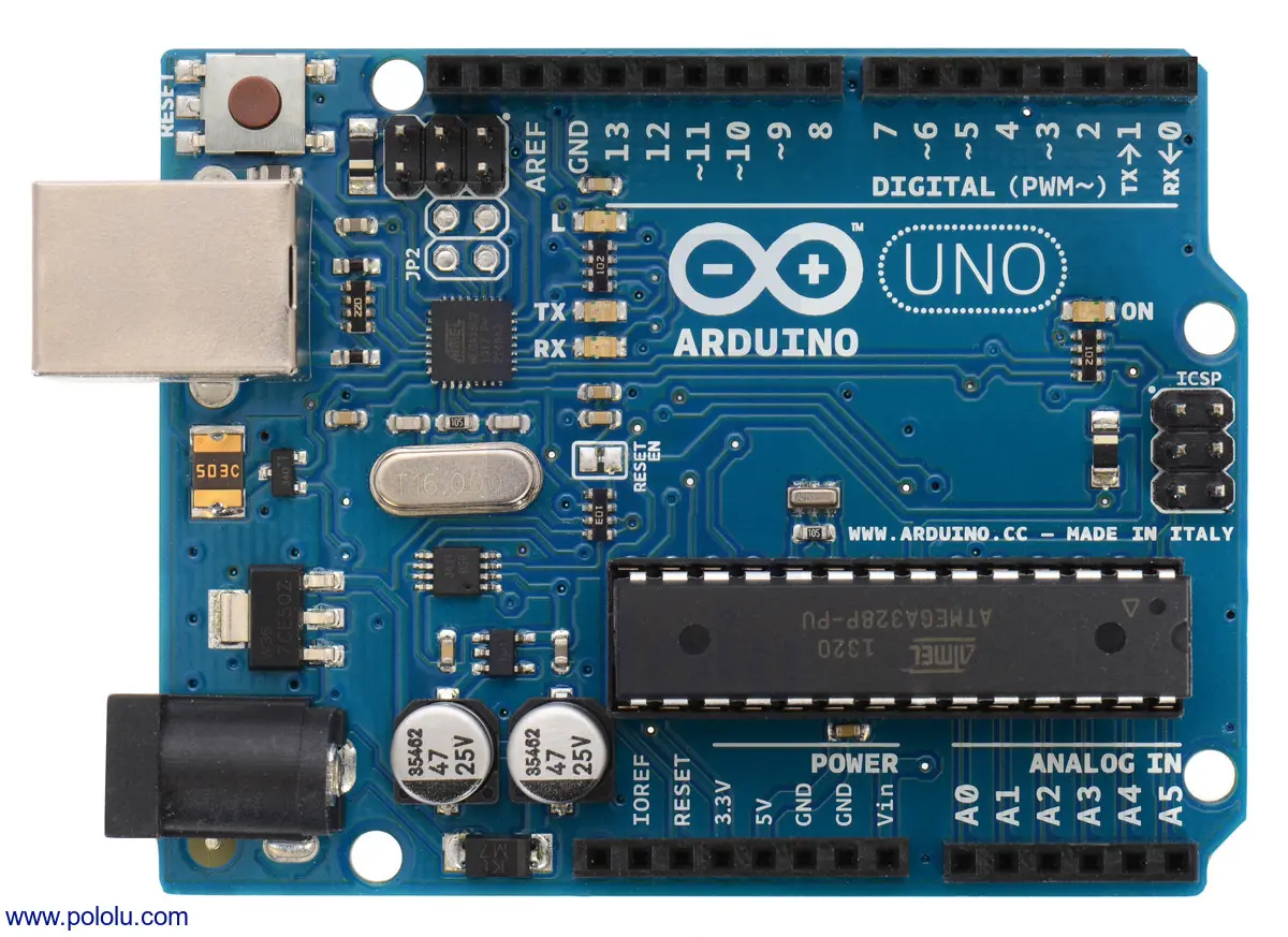
Arduino UNO R3
The Arduino UNO R3 is one of the most popular development boards for learning embedded systems. It is widely used in education and beginner projects to control LEDs, sensors, motors, and other electronic components.
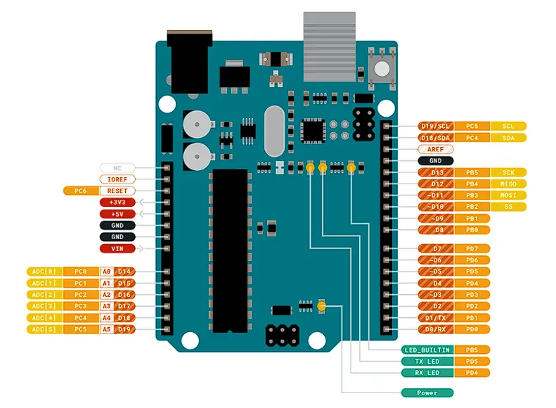
Development Board Overview
Based on the ATmega328P microcontroller, the UNO R3 operates at 5 V logic and is ideal for beginners and simple embedded applications.
| Feature | Specification |
|---|---|
| Digital Pins | 14 |
| PWM | 6 |
| Analog Inputs | 6 |
| Operating Voltage | 5 V |
| Main MCU | ATmega328P |
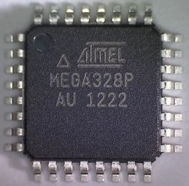
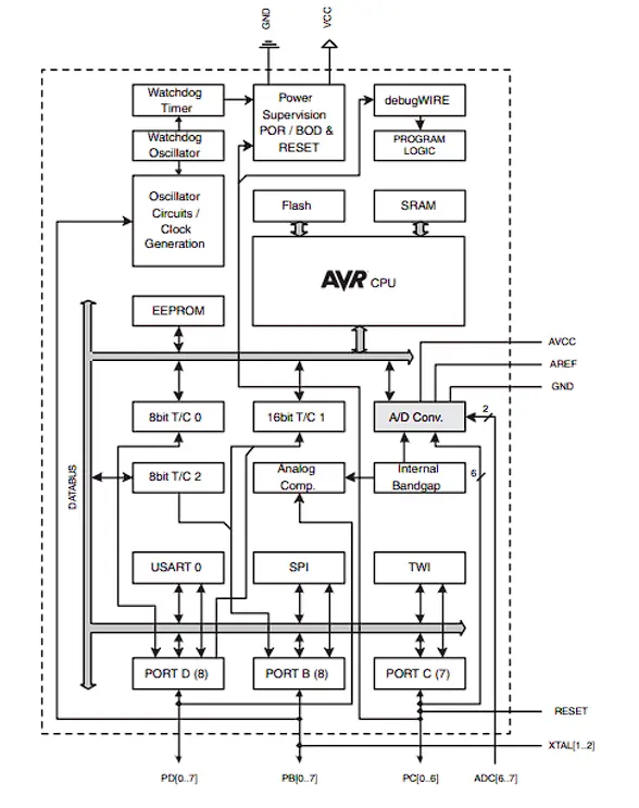
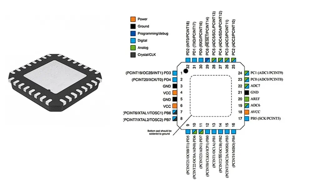
Microcontroller – ATmega328P
The ATmega328P is an 8-bit AVR microcontroller running at 16 MHz. It integrates memory, timers, ADC, and communication interfaces in a single chip.
| Feature | Specification |
|---|---|
| Architecture | 8-bit AVR |
| Flash Memory | 32 kB |
| SRAM | 2 kB |
| EEPROM | 1 kB |
| ADC Resolution | 10-bit |
| Clock Frequency | 16 MHz |
📖 What I Learned from the ATmega328P Datasheet
- Memory map (Section 8): Flash is split into application and boot-loader sections. The 2 kB SRAM starts at address 0x0100 — knowing this helped me understand why Arduino's
Serial.println()can use so much RAM (each string literal is stored there by default unless you use theF()macro). - ADC reference (Section 26): The 10-bit ADC can use an internal 1.1 V reference or the supply voltage (5 V). I learned that the internal reference gives much more stable readings for small sensors, something I missed before just using
analogRead(). - PWM timers (Section 17–19): There are three separate timers. Timer 0 drives
millis()anddelay(); if you reconfigure it for custom PWM you break those functions — a common source of mysterious bugs. - Communication interfaces: UART TX/RX are shared with digital pins 0 and 1, so uploading code fails if anything is connected to those pins — a detail the board overview never mentions.
The Arduino UNO R3 is an ideal board for understanding the fundamentals of embedded systems. Its 8-bit architecture and simple development workflow make it highly suitable for beginners, though it has limited memory and processing power compared to modern boards.
Raspberry Pi Pico 2 W
This board is used for modern embedded system development. It supports wireless connectivity and is flexible for building automation systems, sensor networks, and custom hardware solutions.
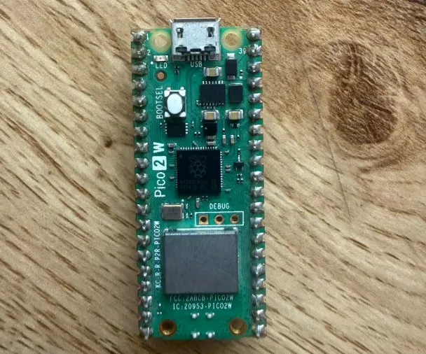
Development Board Overview
The Raspberry Pi Pico 2 W is a compact and powerful development board designed for embedded systems and IoT applications. It integrates a modern dual-core microcontroller and a wireless communication module.
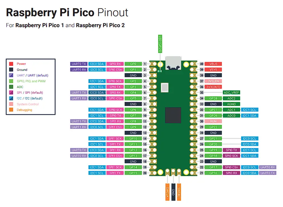
| Feature | Specification |
|---|---|
| Digital GPIO | Up to 30 programmable pins |
| PWM | 16 hardware PWM channels |
| Analog | 12-bit ADC |
| SPI | 2 buses |
| I2C | 2 buses |
| UART | 2 ports |
| Main MCU | RP2350 (ARM Cortex-M33 dual-core) |
| Wireless | WiFi + Bluetooth (CYW43439) |
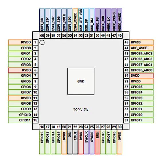
Microcontroller – RP2350
The RP2350 is a 32-bit ARM Cortex-M33 dual-core microcontroller designed for higher performance and security. It includes programmable I/O blocks (PIO), which allow custom hardware communication protocols to be implemented in software.
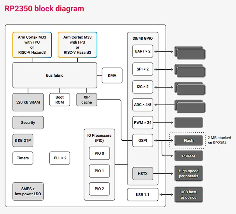
| Feature | Specification |
| Architecture | ARM Cortex-M33 (dual-core) |
| Frequency | Up to 150 MHz |
| SRAM | Up to 520 kB |
| Flash | External (typically 4 MB) |
| ADC | 12-bit |
| PWM | 16 channels |
| PIO | 2 programmable I/O blocks |
Wireless Module – CYW43439
The Pico 2 W integrates the CYW43439 module for WiFi and Bluetooth Low Energy connectivity.
| Feature | Specification |
| WiFi | 802.11 b/g/n (2.4 GHz) |
| Bluetooth | BLE 5.2 |
| Operating Voltage | 3.3 V |
📖 What I Learned from the RP2350 Datasheet
- PIO (Programmable I/O): The RP2350 has two independent PIO blocks, each with four state machines. They can run custom bit-bang protocols (e.g., WS2812 LED strips, custom SPI variants) entirely in hardware without CPU involvement — a concept that does not exist on AVR boards.
- External Flash boot: The chip has no internal Flash. At power-on it executes a small boot ROM that copies your program from the external SPI Flash into SRAM. This means fast random access, but also that your .uf2 file must fit the flash chip on the board.
- Dual-core architecture: Both Cortex-M33 cores share the same SRAM banks. The datasheet documents which spinlock registers must be used to safely share data between cores — I had not thought about thread-safety in a microcontroller context before.
- ADC input impedance: The datasheet specifies a maximum source impedance of ~10 kΩ for accurate 12-bit reads. Anything higher requires a buffer — relevant when reading from high-impedance sensors.
The Raspberry Pi Pico 2 W combines modern ARM architecture with integrated wireless communication. Its dual-core design and PIO blocks provide flexibility for advanced hardware control. It supports both traditional C/C++ and MicroPython development.
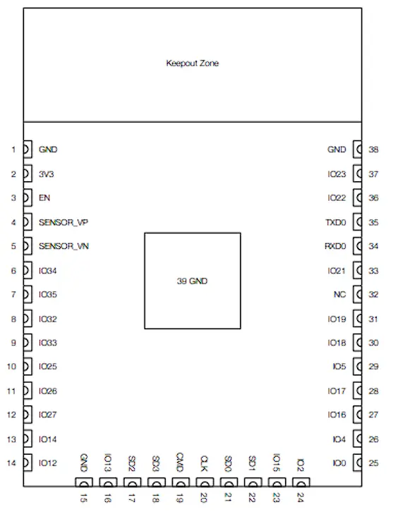
ESP32 (WROOM)
The ESP32 is widely used for Internet of Things (IoT) projects. It enables wireless communication through WiFi and Bluetooth, allowing devices to connect to networks, send data, and interact remotely.
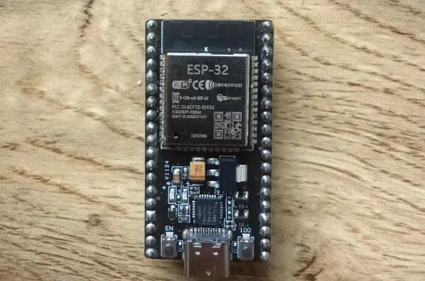
Development Board Overview
The ESP32 development board integrates a powerful dual-core processor and built-in WiFi and Bluetooth. It operates at 3.3 V logic and is widely used for smart devices, home automation, and wireless control systems.
| Feature | Specification |
| Digital GPIO | Up to 34 pins |
| PWM | Hardware PWM (LEDC) |
| Analog | 12-bit ADC |
| DAC | 2 channels (8-bit) |
| SPI | 4 buses |
| I2C | 2 buses |
| UART | 3 ports |
| Main MCU | Xtensa LX6 |
| Wireless | WiFi + Bluetooth |
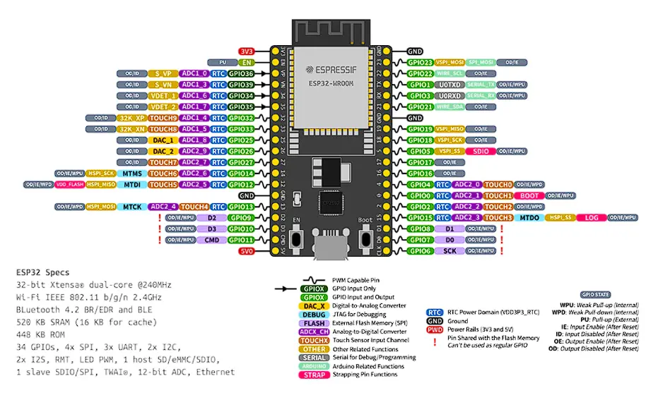
Microcontroller – Xtensa LX6
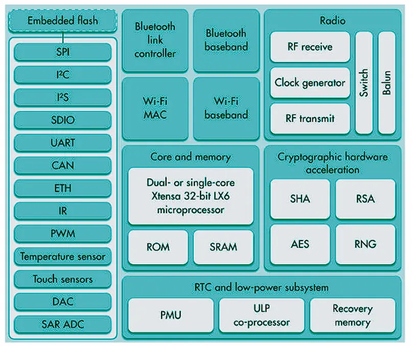
The ESP32 uses a 32-bit dual-core Xtensa LX6 architecture optimized for wireless communication and real-time applications. It integrates advanced peripherals, hardware encryption, and deep sleep modes for low power consumption.
| Feature | Specification |
|---|---|
| Architecture | Xtensa LX6 (dual-core) |
| Frequency | Up to 240 MHz |
| SRAM | 520 kB |
| Flash | External (usually 4 MB) |
| ADC | 12-bit |
| DAC | 2× 8-bit |
| WiFi | Integrated |
| Bluetooth | Classic + BLE |
📖 What I Learned from the ESP32 Datasheet
- ADC non-linearity warning: The datasheet documents a known non-linearity in the ADC near the top and bottom of its range (roughly below 100 mV and above 3.1 V). For accurate analog readings you must either apply a calibration curve or keep your signal within the linear zone — this surprised me compared to the simpler AVR ADC.
- GPIO strapping pins: Several GPIO pins double as boot-mode strapping pins (GPIO0, GPIO2, GPIO12, GPIO15). Pulling them high or low at power-on changes which boot mode the chip enters. The datasheet explains this in the "Strapping Pins" section — critical to know before connecting peripherals to those pins.
- Touch sensor peripheral: The ESP32 has ten capacitive-touch-capable GPIO pins. The datasheet describes the charge/discharge cycle used to detect touch — I had not realized this capability existed without an external sensor IC.
- Deep sleep current: The deep-sleep mode draws as little as 10 µA. Understanding the wakeup sources (timer, external GPIO, ULP co-processor) from the power management section is what makes battery-powered IoT devices practical with this chip.
The ESP32 is a powerful dual-core microcontroller designed for IoT and wireless applications. Compared to traditional Arduino boards, it offers significantly higher processing speed and memory, allowing for more complex real-time applications.
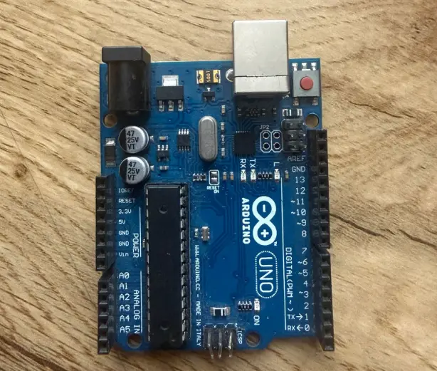
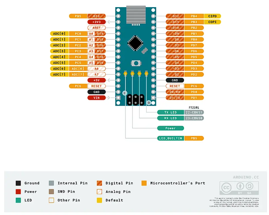
Arduino Nano
The Arduino Nano offers similar functionality to the UNO but in a much smaller form factor. It is commonly used in compact or space-limited projects, such as wearable devices or small embedded prototypes.
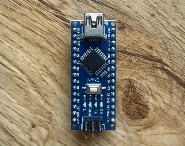
Development Board Overview
The Arduino Nano uses the same ATmega328P microcontroller as the UNO R3 but in a smaller form factor, ideal for space-limited projects.
| Feature | Specification |
|---|---|
| Digital Pins | 14 |
| PWM | 6 |
| Analog Inputs | 8 |
| Operating Voltage | 5 V |
| Main MCU | ATmega328P |
Microcontroller – ATmega328P
The Arduino Nano uses the same 8-bit AVR ATmega328P found in the UNO R3. It runs at 16 MHz and includes internal Flash memory, SRAM, EEPROM, ADC, timers, and communication interfaces.
| Feature | Specification |
|---|---|
| Architecture | 8-bit AVR |
| Flash | 32 kB |
| SRAM | 2 kB |
| EEPROM | 1 kB |
| ADC | 10-bit |
| Frequency | 16 MHz |
Difference Between Arduino Nano and Arduino UNO R3
| Feature | Arduino Nano | Arduino UNO R3 |
|---|---|---|
| Size | Compact | Larger board |
| USB | Mini/Micro USB | USB Type-B |
| Analog Pins | 8 | 6 |
| Shield Compatibility | No direct shield stacking | Compatible with Arduino shields |
| Form Factor | Breadboard friendly | Standard Arduino layout |
The Arduino Nano offers the same functionality as the UNO R3 in a compact, breadboard-friendly format. It is especially useful for space-constrained projects and embedded prototypes where physical size matters.
Group Assignment Reflection
During the group assignment, I learned that reading a microcontroller datasheet is essential to understand the real capabilities and limitations of each board. I understood how factors such as architecture, clock frequency, memory, voltage logic, and communication protocols influence board selection for different embedded applications. This process also helped me distinguish between a development board and the microcontroller it contains, and improved my ability to compare platforms using technical information in a more objective and engineering-based way.
Development Boards Comparison
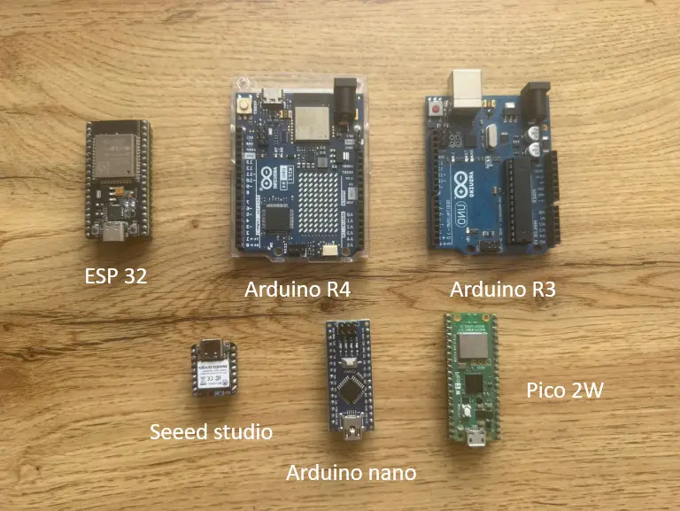
| Feature | UNO R3 | Nano | UNO R4 WiFi | ESP32 | Pico 2 W |
|---|---|---|---|---|---|
| Main MCU | ATmega328P | ATmega328P | R7FA4M1 (ARM M4) | Xtensa LX6 | RP2350 |
| Architecture | 8-bit AVR | 8-bit AVR | 32-bit ARM Cortex-M4 | 32-bit Xtensa (dual-core) | 32-bit ARM Cortex-M33 (dual-core) |
| Clock Speed | 16 MHz | 16 MHz | 48 MHz | Up to 240 MHz | Up to 150 MHz |
| Flash Memory | 32 kB | 32 kB | 256 kB | External (~4 MB) | External (~4 MB) |
| SRAM | 2 kB | 2 kB | 32 kB | 520 kB | Up to 520 kB |
| WiFi | No | No | Yes | Yes | Yes |
| Bluetooth | No | No | BLE | BLE | BLE |
Individual Assignment
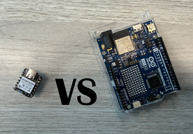
In this individual assignment, I test and compare two different microcontroller boards: the Seeed Studio XIAO nRF52840 ("Seeeduino") and the Arduino UNO R4. The objective is to evaluate their behavior, compatibility, and performance for embedded systems development.
Before working with the physical boards, I first used a simulation environment (Tinkercad). This allows me to validate the circuit design, test the code, and detect possible errors in a safe and controlled way before risking real hardware.
Programming Process & Toolchain
Both boards were programmed using the Arduino IDE 2. The steps below describe the complete setup from a fresh install to uploading the first program.
Arduino UNO R4 — Toolchain Setup
-
Install board package via Board Manager Open Tools → Board → Boards Manager, search for
Arduino UNO R4, and install the Arduino UNO R4 Boards package (by Arduino). This adds the Renesas RA4M1 compiler toolchain and upload tools automatically. -
Select the board Tools → Board → Arduino UNO R4 Boards → Arduino UNO R4 WiFi (or Minima, depending on your hardware).
-
Select the port Connect the board via USB, then go to Tools → Port and select the port that appears (e.g.,
COM3on Windows or/dev/ttyACM0on Linux/macOS). If no port appears, the CH340/CP2102 USB-serial driver may need to be installed. -
Serial Monitor baud rate All exercises in this week use
Serial.begin(9600). The Serial Monitor (Tools → Serial Monitor or Ctrl+Shift+M) must be set to 9600 baud to read output correctly. Mismatch produces garbled text. -
Libraries installed Exercise 3 (LED Matrix) requires the Arduino_LED_Matrix library. Install via Tools → Manage Libraries → search "Arduino_LED_Matrix". This library ships with the UNO R4 board package so it is usually already available after step 1.
-
Upload Press the Upload button (→) or Ctrl+U. The IDE compiles, then transfers the .bin file via the onboard USB bootloader. The board resets automatically and the sketch starts running.
LED_BUILTIN refers to the single green LED at pin 13, not the 12×8 LED matrix. To control the matrix you must use the Arduino_LED_Matrix library, as shown in Exercise 3.
Seeed Studio XIAO nRF52840 — Toolchain Setup
-
Add the Seeed board manager URL Open File → Preferences (Arduino IDE 2) and paste the following URL into "Additional boards manager URLs":
https://files.seeedstudio.com/arduino/package_seeeduino_boards_index.json -
Install the Seeed nRF52 package Open Tools → Boards Manager, search for
Seeed nRF52, and install Seeed nRF52 Boards. This downloads the ARM GCC toolchain for the nRF52840 Cortex-M4F core. -
Select the board Tools → Board → Seeed nRF52 Boards → Seeed XIAO nRF52840. (If you have the Sense variant with IMU and microphone, choose Seeed XIAO nRF52840 Sense instead.)
-
Select the port Same as UNO R4 — connect via USB-C and choose the port under Tools → Port. The XIAO appears as a CDC serial device; no extra driver is needed on most systems.
-
Serial Monitor baud rate Exercise 1 uses
Serial.begin(9600). Set the monitor to 9600 baud. -
3.3 V logic — important hardware note The XIAO nRF52840 GPIO is 3.3 V only. Never connect a 5 V signal directly to its pins. When testing alongside 5 V Arduino boards, use a logic level converter or voltage divider on any shared signal lines.
-
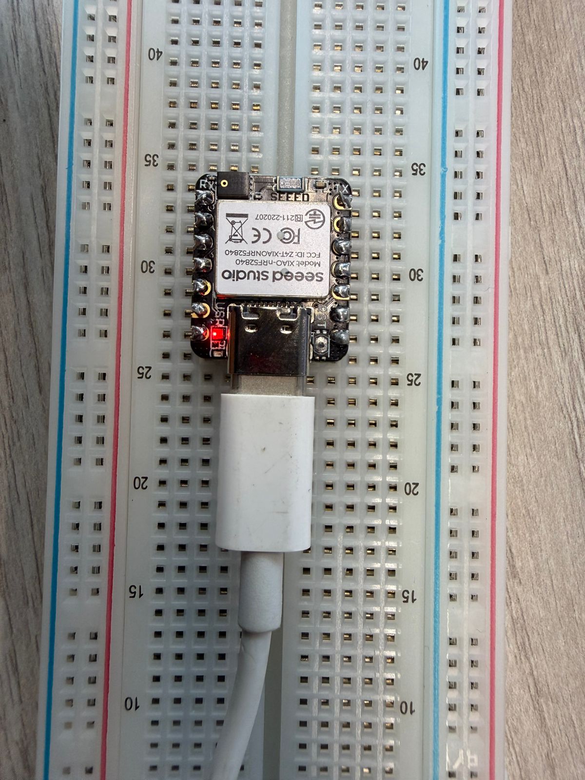
Upload Press Upload. The first upload after a fresh install may take longer because the toolchain is being used for the first time. If the upload fails, double-tap the RESET button to put the board into bootloader mode (the orange LED pulses slowly).
| Setting | Arduino UNO R4 | Seeed XIAO nRF52840 |
|---|---|---|
| Board package | Arduino UNO R4 Boards | Seeed nRF52 Boards |
| Extra board manager URL | None (built-in) | files.seeedstudio.com JSON |
| Serial baud rate | 9600 | 9600 |
| Logic voltage | 5 V | 3.3 V |
| LED Matrix library | Arduino_LED_Matrix (Exercise 3) | N/A |
| Bootloader recovery | Auto on upload | Double-tap RESET |
1) Embedded Systems
An embedded system is a specialized computing system designed to perform a specific task within a larger device or process. Unlike general-purpose computers, embedded systems are built for dedicated functions such as sensing, control, automation, and real-time interaction.
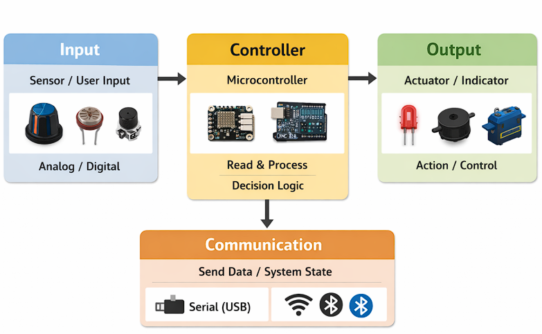
Basic Composition: Input → Controller → Output
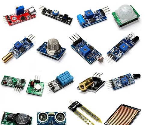
- Input: Sensors or user inputs that provide data (e.g., button, LDR, potentiometer).
- Controller: The microcontroller that reads inputs, processes information, and makes decisions.
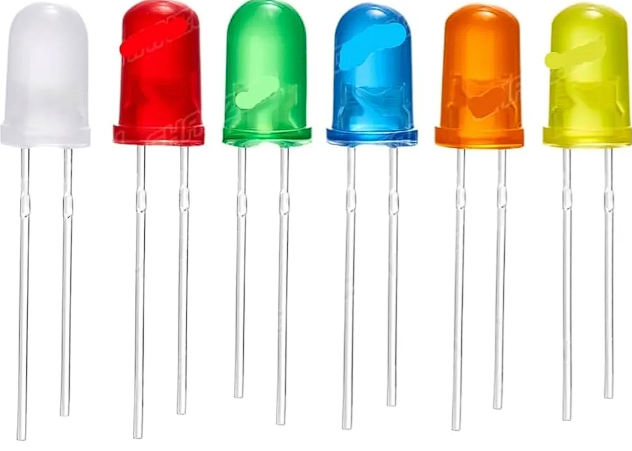
- Output: Actuators or indicators controlled by the system (e.g., LED, buzzer, motor, LED matrix).
Input
Controller
Output
2) System Architecture
The embedded workflow follows a standard architecture: the controller reads an input signal, processes it, and produces an output action. It can also communicate measured values to a computer or another device.
Workflow
- Read input: Acquire data from a sensor or button (analog/digital).
- Process data: Filter, average, debounce, or compare against a threshold.
- Decision: Determine the system state (e.g., ON/OFF, alert/normal).
- Drive output: Activate an actuator (LED, buzzer, motor, LED matrix).
- Communicate: Send values through Serial (wired) or WiFi/BLE (wireless).
3) Safety First: Simulation Before Hardware (Tinkercad)
Before building any circuit physically, I tested the logic and wiring in Tinkercad. Simulating first validates connections and program behavior in a controlled environment, reducing the risk of short circuits, incorrect pin usage, or damaging the board.
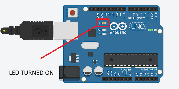
Exercise 2.1 — Onboard LED blink
In the simulation, the onboard LED responded immediately after uploading the code. The LED toggled at the programmed interval without delays or unstable behavior, confirming correct digital output configuration.
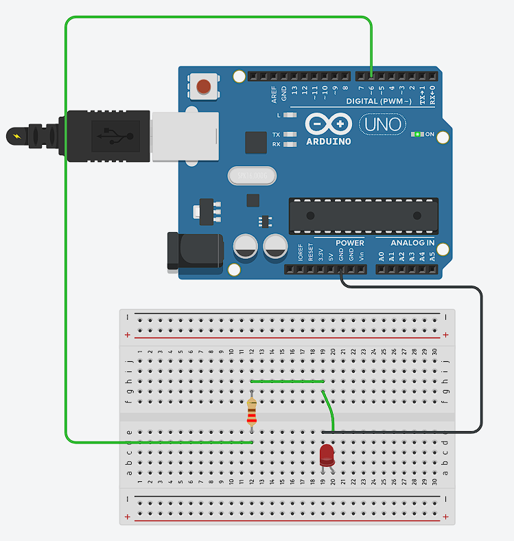
Exercise 2.2 — External LED on breadboard
The external LED connected through the breadboard behaved as expected. The resistor correctly limited the current and no abnormal behavior was observed. The simulation confirmed correct wiring and component polarity before assembling the real circuit.
4) Exercises
Three exercises demonstrate embedded interaction and communication-ready structure: (1) Seeeduino blinking an LED, (2) Arduino UNO R4 blinking an LED (onboard and external), and (3) Arduino UNO R4 controlling the built-in LED matrix.
Exercise 1 — Seeed Studio XIAO nRF52840: Blink LED
This program turns an LED on and off repeatedly using the onboard LED (LED_BUILTIN).
// Exercise 1: Seeed Studio XIAO nRF52840 — Blink LED
// Based on the standard Arduino Blink example.
// LED_BUILTIN on the XIAO nRF52840 is the built-in blue LED (active LOW on some variants).
const int LED_PIN = LED_BUILTIN;

void setup() {
  pinMode(LED_PIN, OUTPUT);  // Configure pin as digital output
}

void loop() {
  digitalWrite(LED_PIN, HIGH);  // Turn LED on
  delay(500);                   // Wait 500 ms
  digitalWrite(LED_PIN, LOW);   // Turn LED off
  delay(500);                   // Wait 500 ms
  // Result: LED blinks at 1 Hz (one full cycle per second)
}
How it works: pinMode() tells the microcontroller to treat the pin as a voltage output rather than an input. digitalWrite(HIGH) sets the pin to its supply voltage (3.3 V on this board), turning the LED on. delay(500) pauses execution for 500 milliseconds. Repeating HIGH → delay → LOW → delay produces a visible 1 Hz blink.
Exercise 2 — Arduino UNO R4: Blink LED (onboard)
Same concept as Exercise 1, now verified on the Arduino UNO R4 to confirm the toolchain and board selection are correct.
Code origin: adapted from the Arduino Blink example with a faster delay (300 ms) to visually distinguish it from Exercise 1.// Exercise 2: Arduino UNO R4 — Blink onboard LED
// LED_BUILTIN on the UNO R4 is the green LED at pin 13.
const int LED_PIN = LED_BUILTIN;
void setup() {
pinMode(LED_PIN, OUTPUT);
}
void loop() {
digitalWrite(LED_PIN, HIGH); // LED on
delay(300); // 300 ms on
digitalWrite(LED_PIN, LOW); // LED off
delay(300); // 300 ms off
// Result: LED blinks at ~1.67 Hz
}Exercise 2 (continued) — Arduino UNO R4: External LED on pin 6
For the physical implementation, I connected an external LED to digital pin 6 through a 220 Ω current-limiting resistor. The resistor is calculated from Ohm's law: V = I × R → R = (5 V − 2 V forward voltage) / 20 mA ≈ 150 Ω minimum; 220 Ω provides a safety margin.
Code origin: written from scratch. The only change from the onboard example is replacingLED_BUILTIN with an explicit pin number (6).
// Exercise 2: Arduino UNO R4 — External LED on pin 6
// Hardware: LED anode → 220 Ω resistor → pin 6; LED cathode → GND
const int LED_PIN = 6;
void setup() {
pinMode(LED_PIN, OUTPUT);
}
void loop() {
digitalWrite(LED_PIN, HIGH); // 5 V on pin 6 → current through resistor → LED on
delay(300);
digitalWrite(LED_PIN, LOW); // 0 V on pin 6 → no current → LED off
delay(300);
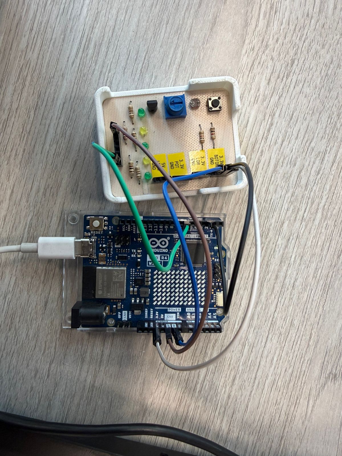
}Exercise 2 (continued) — Button-controlled LED
I added a push button on pin 2 to introduce user interaction. The button is wired between pin 2 and GND; INPUT_PULLUP enables the microcontroller's internal pull-up resistor, so the pin reads HIGH when the button is released and LOW when pressed.
// Arduino UNO R4 — LED controlled by push button on pin 2
// Wiring: button between pin 2 and GND (INPUT_PULLUP does the rest)
const int buttonPin = 2;
const int ledPin    = 6;

void setup() {
  pinMode(buttonPin, INPUT_PULLUP);  // Internal pull-up: HIGH = released, LOW = pressed
  pinMode(ledPin, OUTPUT);
}

void loop() {
  int buttonState = digitalRead(buttonPin);

  if (buttonState == LOW) {      // Button pressed → LOW because pin is pulled to GND
    digitalWrite(ledPin, HIGH);  // LED on
  } else {
    digitalWrite(ledPin, LOW);   // LED off
  }
  // No delay needed — digitalRead is fast enough for a button
}
Exercise 3 — Arduino UNO R4 WiFi: Built-in LED Matrix
The UNO R4 WiFi has a 12×8 LED matrix controlled by a dedicated driver IC. The Arduino_LED_Matrix library abstracts the row/column addressing into a simple pixel array.
// Exercise 3: Arduino UNO R4 WiFi — Built-in LED Matrix
// Library: Arduino_LED_Matrix (installed via Boards Manager with UNO R4 package)
// The matrix is 12 columns × 8 rows = 96 pixels
#include <Arduino_LED_Matrix.h>

ArduinoLEDMatrix matrix;

// Frame buffer: uint8_t[8][12] — row-major, 1 = on, 0 = off
uint8_t frame[8][12] = {0};  // Start with all pixels off

void setup() {
  matrix.begin();         // Initialize the matrix driver
  frame[0][0] = 1;        // Turn on pixel at row 0, column 0 (top-left corner)
  matrix.loadPixels(frame, sizeof(frame));  // Push the frame to the display
}

void loop() {
  // Nothing to update — static frame stays on
}
How it works: matrix.begin() initializes the SPI-like bus between the RA4M1 and the LED driver. frame[row][col] = 1 sets a pixel in the software buffer. matrix.loadPixels() transfers that buffer to the hardware. To animate, you would modify the frame array in loop() and call loadPixels() again each iteration.
5) Technical Comparison: Seeed Studio XIAO nRF52840 vs Arduino UNO R4
Both controllers can run embedded applications (read inputs, process data, drive outputs, and communicate), but they differ in processing, memory, logic voltage, and onboard features.
| Feature | Seeed Studio XIAO nRF52840 | Arduino UNO R4 (Minima / WiFi) |
|---|---|---|
| Microcontroller | Nordic nRF52840 (Arm Cortex-M4F) | Renesas RA4M1 (Arm Cortex-M4) |
| Clock speed | Up to 64 MHz | 48 MHz |
| Memory (Flash / RAM) | 1 MB Flash / 256 KB RAM + 2 MB QSPI Flash | 256 KB Flash / 32 KB RAM |
| Logic / Operating voltage | 3.3 V (⚠️ not 5 V tolerant) | 5 V (UNO-style compatibility) |
| Wireless connectivity | Bluetooth LE + NFC | Minima: none · WiFi: ESP32-S3 (WiFi + BLE) |
| Communication interfaces | I2C, UART, SPI | UART, I2C, SPI, CAN + DAC |
| Onboard special features | Very compact; Sense variant adds IMU + mic | WiFi model: 12×8 LED matrix |
| Best fit | Compact BLE/NFC, low-power wearables, TinyML | Classic Arduino ecosystem, 5 V modules, education |