Assignments
Week 3 – Computer-Controlled Cutting
Assignment
Group assignment
- Do your lab's safety training
-
Characterize your laser cutter:
- Focus
- Power
- Speed
- Rate
- Kerf
- Joint clearance
- Joint types
Individual assignment
- Cut something on the vinyl cutter
- Design, laser cut, and document a parametric construction kit, accounting for the laser cutter kerf
- Extra credit: Design it to be assembled in multiple ways
- Extra credit: Include elements that aren't flat
- Extra credit: Engrave as well as cut
Group Reflection
In this week, lab safety training was important to understand the equipment and work safely. Testing different parameters helped us identify the best settings and make better decisions during fabrication. Overall, this process improved our confidence and ensured more precise results. Additionally, we learned to recognize the different types of CNC machines that exist and their specific applications.
🔗 If you want to explore the Group Assignment in more detail, you can visit the official Fab Academy page:
Visit Fab Academy ULima →CNC Machine
A CNC (Computer Numerical Control) machine is a computer-controlled tool that performs precise movements based on a digital design. Depending on the tool or manufacturing process used, a CNC machine can perform different tasks.
For example, a CNC machine can work as:
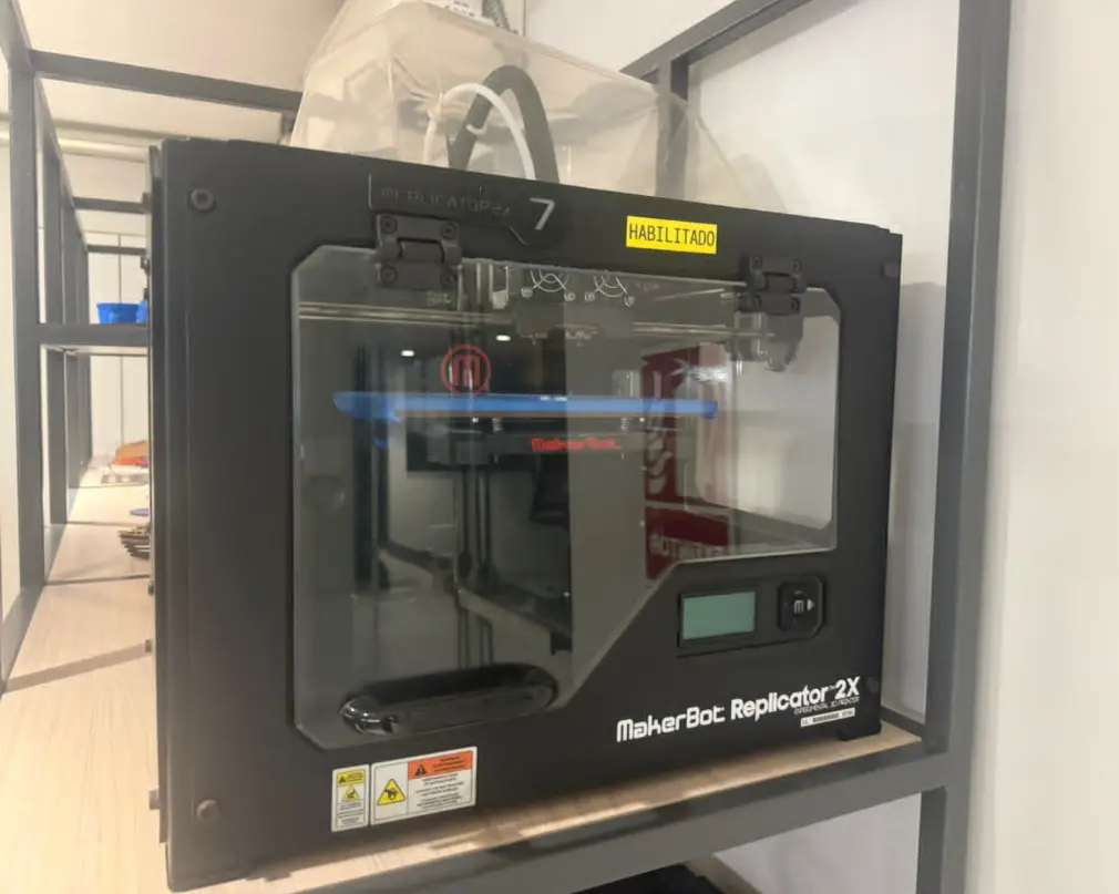
3D Printer
By depositing material layer by layer
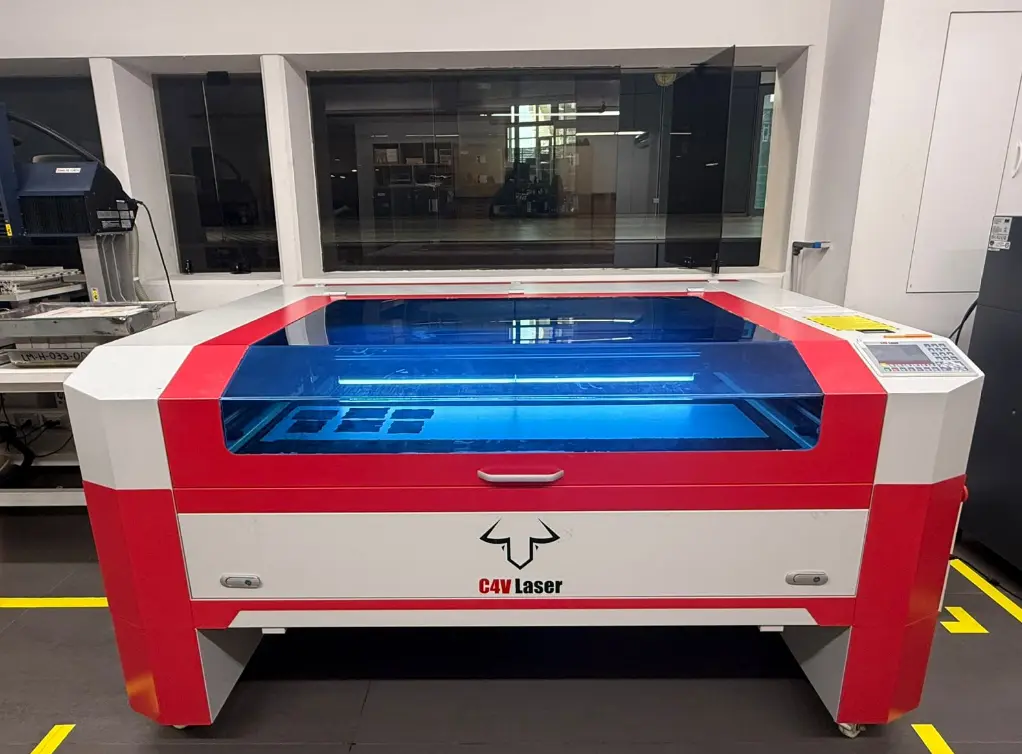
Laser Cutter
By cutting material using a laser beam
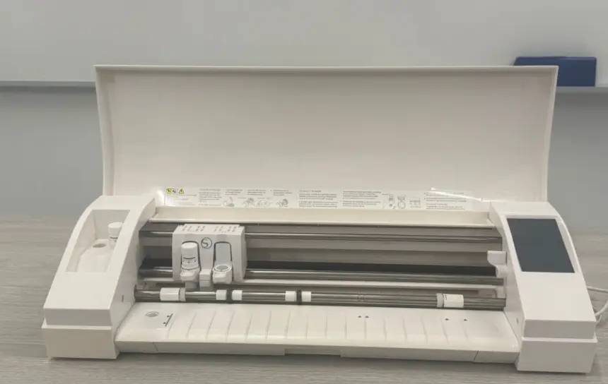
Vinyl Cutter
For thin and flexible materials
In all cases, the machine follows instructions generated from CAD/CAM software.
Security Lab – Laser Cutter Components
The CNC laser cutter uses a CO₂ laser to cut and engrave materials such as MDF, acrylic, and cardboard. It follows vector paths for high precision and clean cuts.
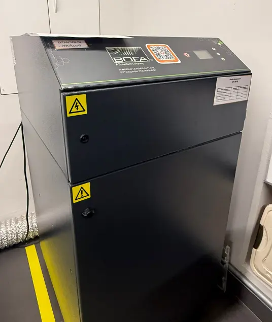
The fume extraction system removes smoke and gases, ensuring a safe working environment and protecting both the user and the machine.
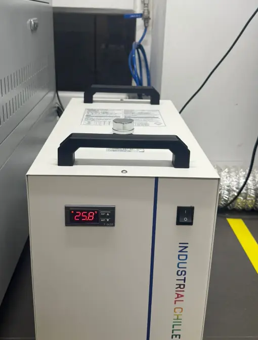
The water chiller cools the laser tube, preventing overheating and ensuring stable performance.
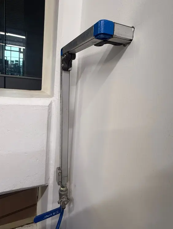
The air assist system reduces burning and fire risk by blowing air directly onto the cutting area.
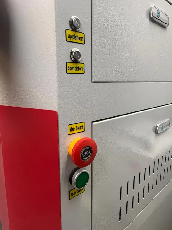
Safety controls include bed adjustment buttons and emergency switches to safely operate the machine.
Laser Engraving Test
Initial Design Preparation
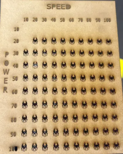
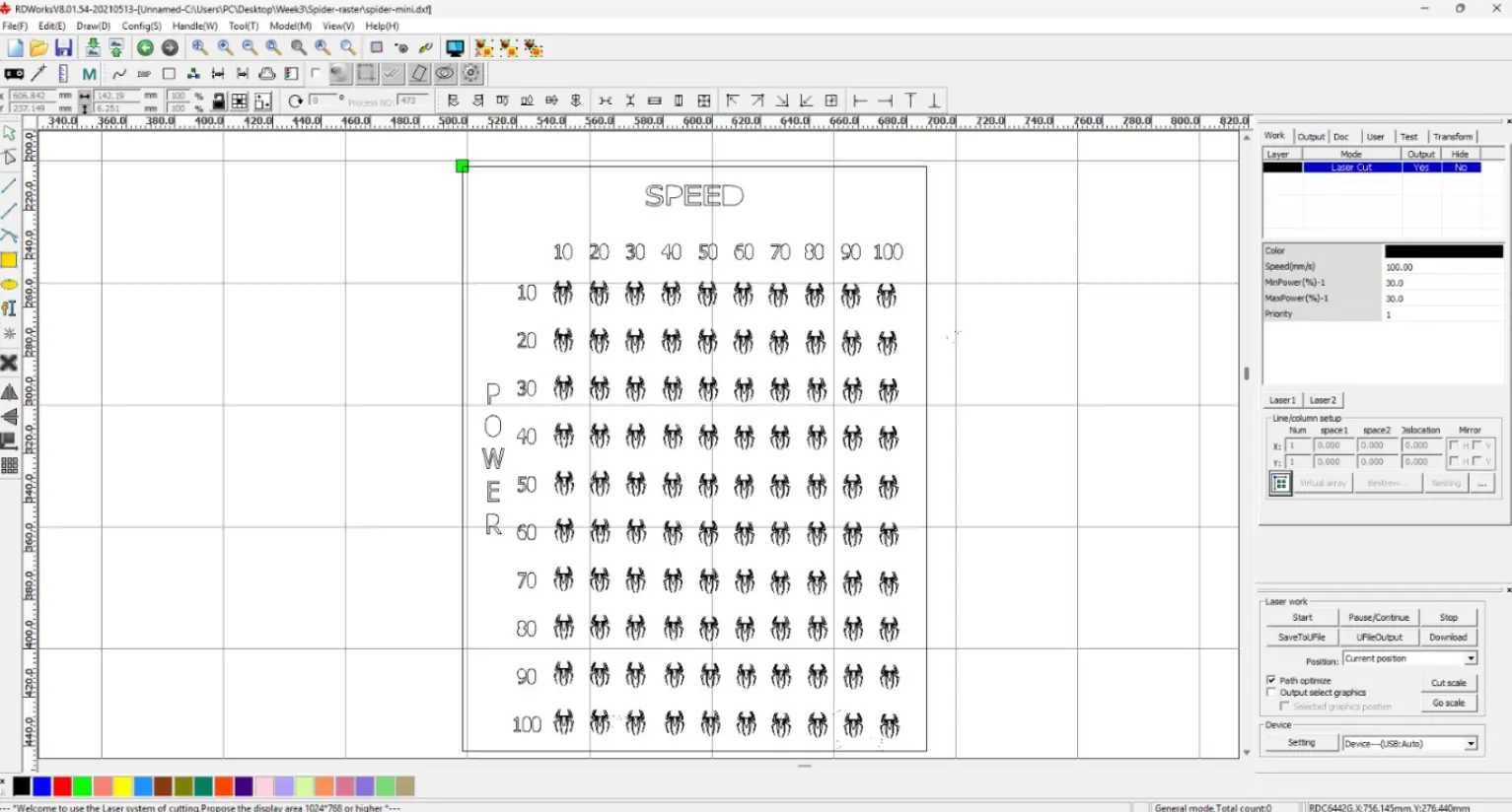
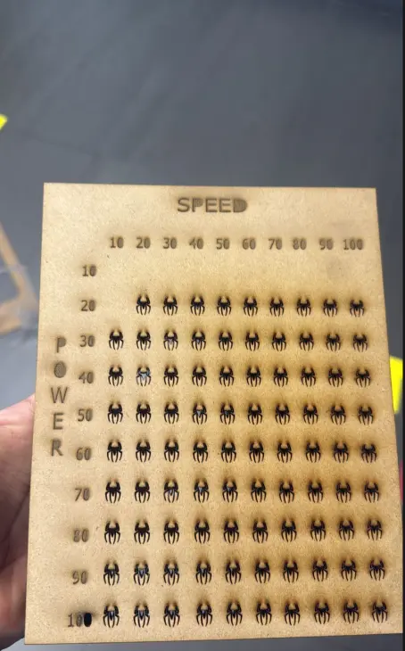
We prepared a small engraving test file to evaluate how different laser parameters affect the material. The design included multiple small figures arranged in a grid.
Parameter Variation Strategy
Each row and column of the design was assigned a different parameter. This allowed us to compare variations in engraving quality. The main variables tested were Speed and Power.
Color-Based Parameter Control
Different colors were assigned to the design elements. In the laser software, each color corresponds to specific speed and power settings. This allows multiple engraving configurations in a single job.
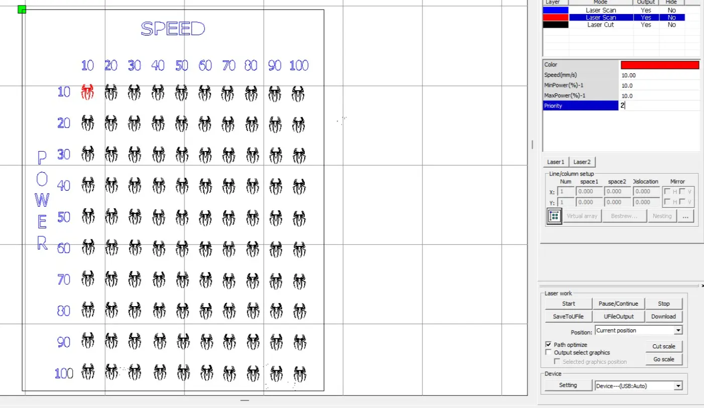
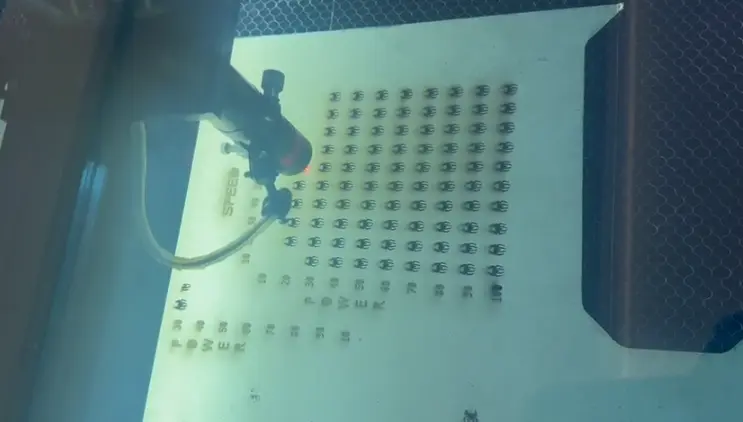
Laser Testing Process
After configuring the parameters, we executed the engraving test. Some low power values were not strong enough to produce visible engraving. The minimum effective power for our setup was identified through testing.
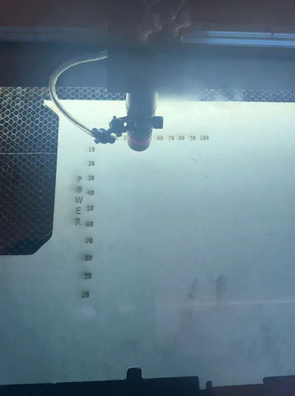
Final Result
The final engraved sample shows a clear comparison between speed and power variations. Higher power values produced darker engravings, while higher speed values reduced engraving intensity. This test helps define optimal settings for future projects.
Individual Assignment
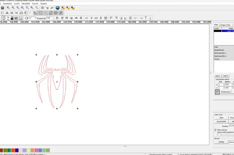
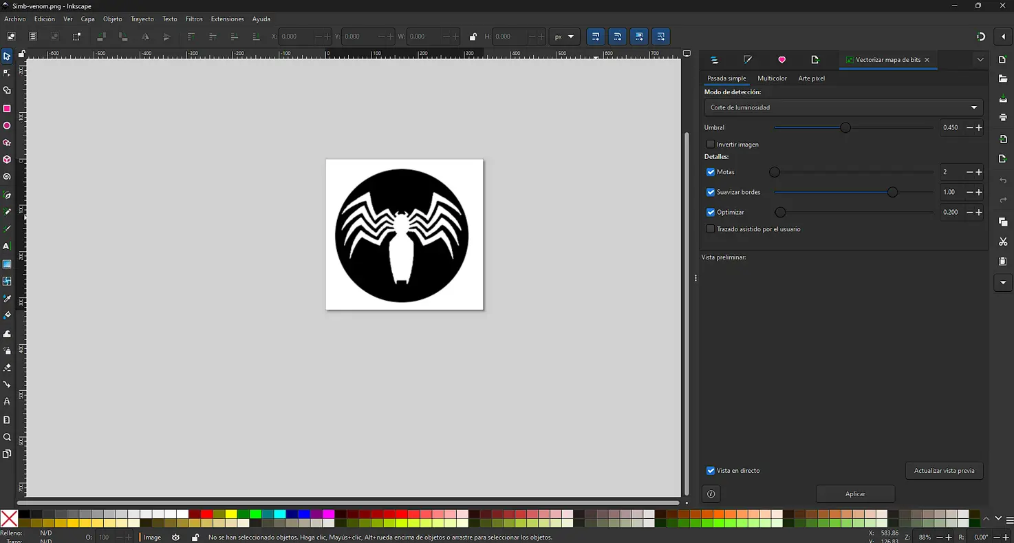
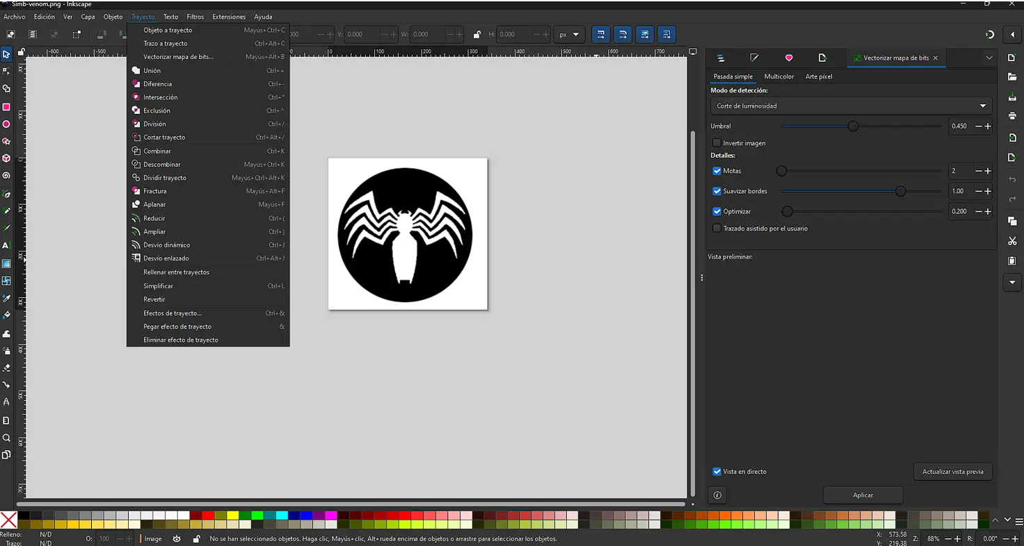
Vectorizing an Image in Inkscape (Trace Bitmap)
I vectorized an image using Inkscape to transform a raster graphic into an editable vector. This is useful for digital fabrication because vectors keep clean edges and can be scaled without losing quality.
For this test, I tried different Trace Bitmap options to compare results and choose the cleanest output.
Workflow
- Import the image in Inkscape: File → Import.
- Open the vectorization tool: Path → Trace Bitmap.
- Choose the tracing method depending on the image (e.g. Single scan for silhouettes).
- Click Apply to generate a vector path.
- Compare and clean the vector, then delete the raster if needed.
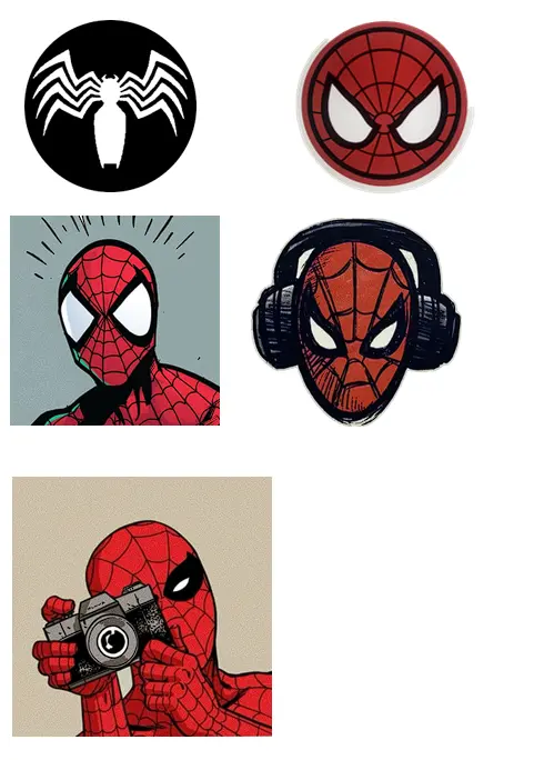
More Vector Experiments
I tested different Spider-Man styles to see how vectorization behaves with various levels of detail and contrast. Each design produced a different tracing result.
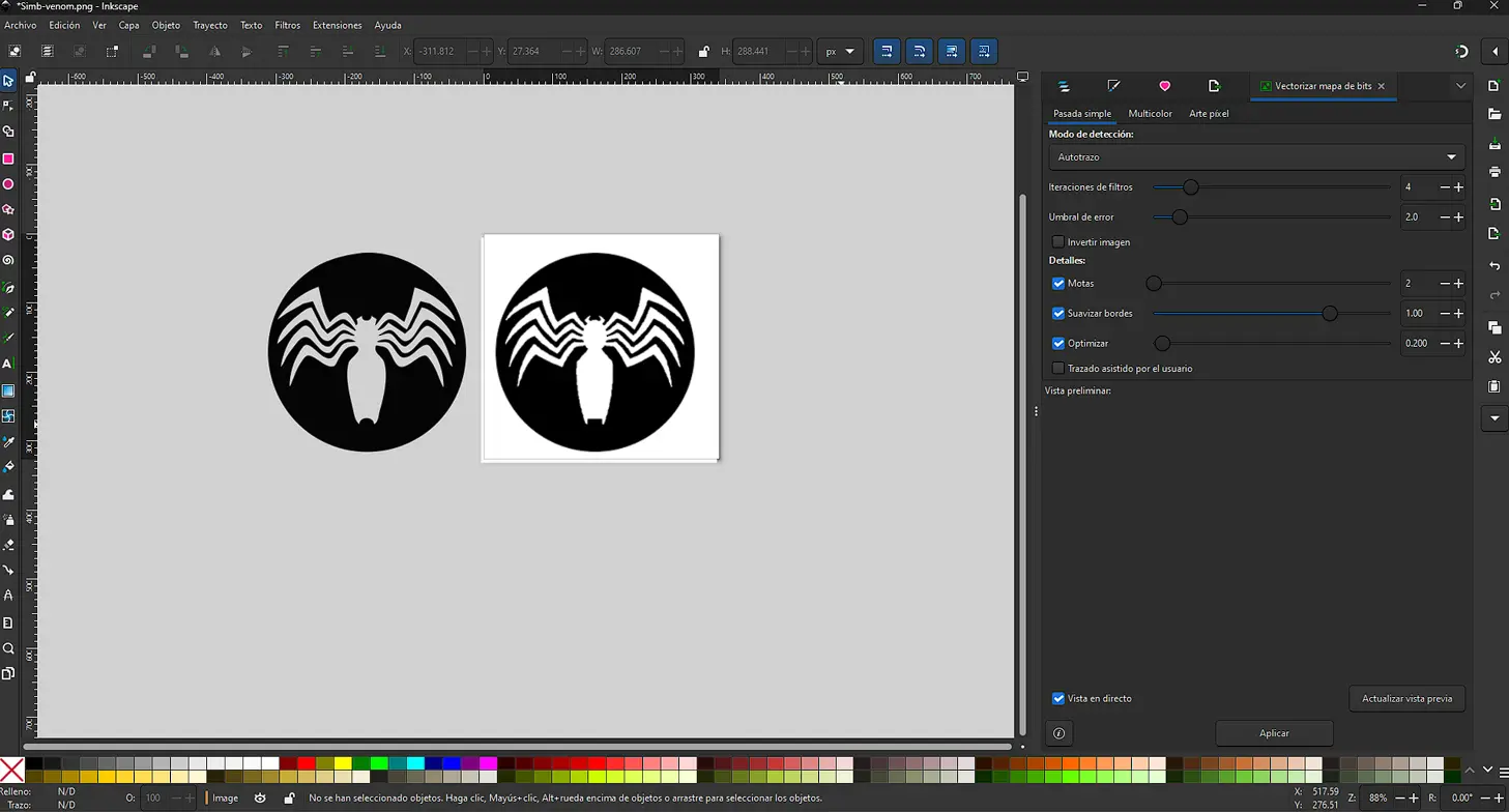
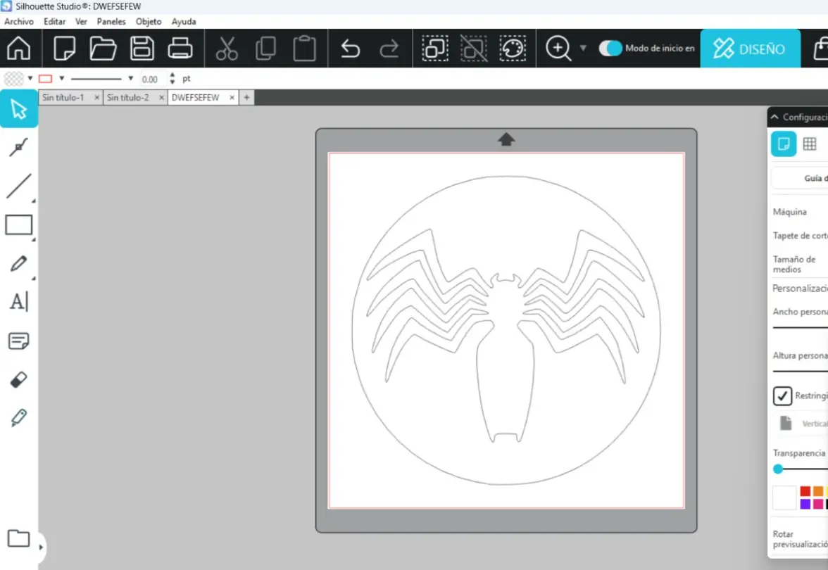
Spider Symbol
Strong silhouette = clean vector result, ready for laser cutting.
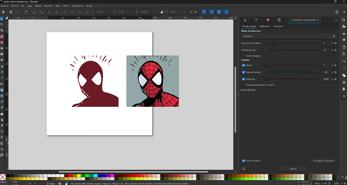
Spider-Sense Effect
Thin lines and motion details helped evaluate how small strokes are captured.
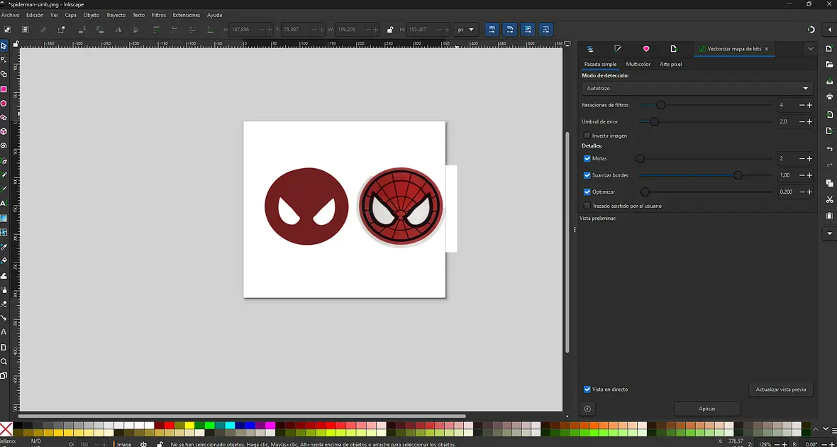
Spider-Man with Headphones
More complex design; some node cleanup was needed but the result looked great.
.webp)
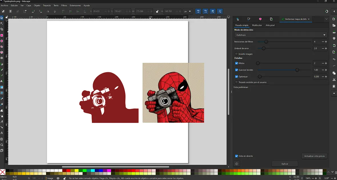
Spider-Man with Camera
Shading and small details required testing different settings to get the best result.
Vinyl Cutting
Exporting the File
Once the vector design was ready in Inkscape, I exported it as a DXF so it could be opened in Silhouette Studio.
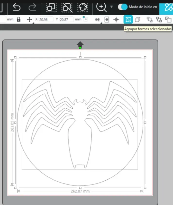
Scaling the Design
After importing, the design was too large. I selected all vectors and scaled them to the desired dimensions while keeping proportions.
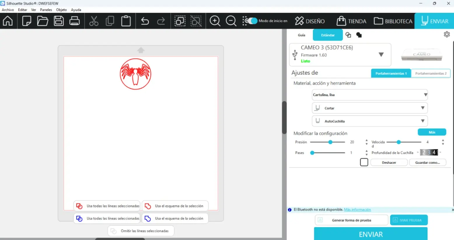
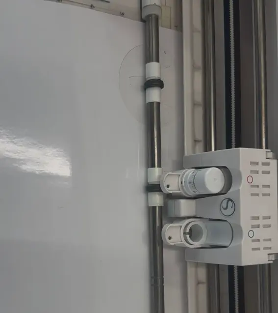
Machine Setup
The cutter was detected by the software. I adjusted blade depth, pressure, speed, and passes according to the material.
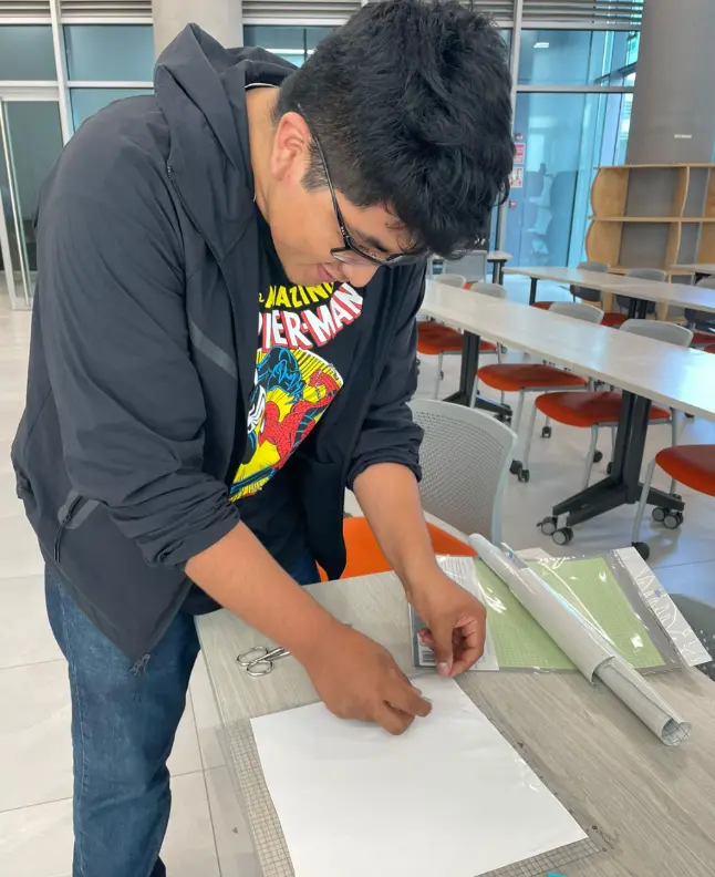
Preparing the Cutting Mat
I placed the adhesive vinyl on the cutting mat and pressed it firmly to avoid movement during cutting.
Sending the File to the Cutter
Once the material was ready, I sent the file to the cutter and the machine followed the vector paths.
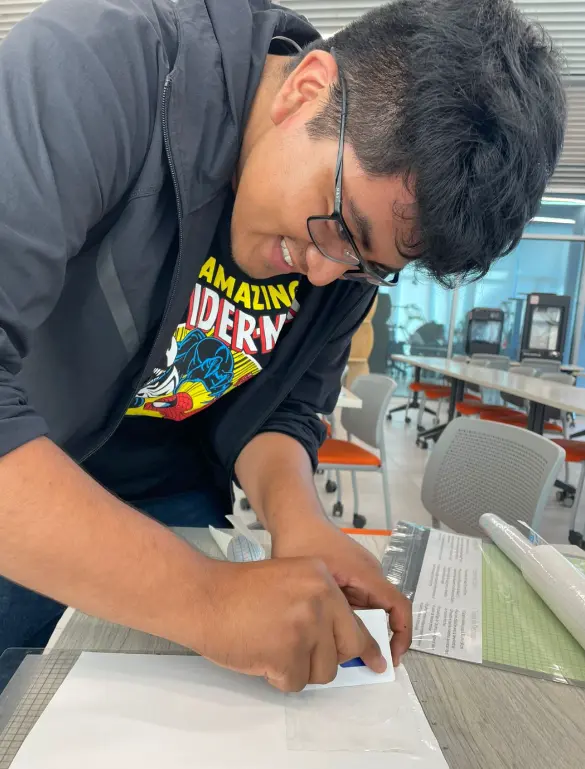
Applying Transfer Tape
Transfer tape was applied on top of the vinyl to keep all parts aligned for placement.
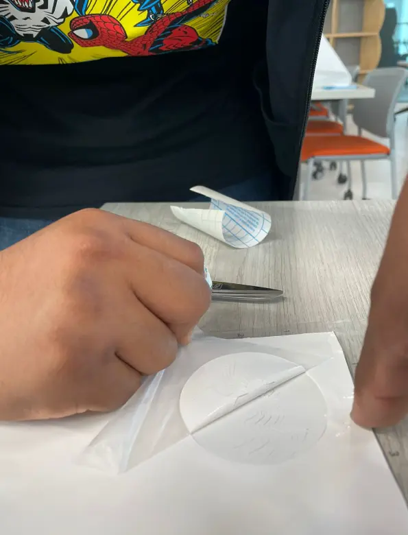
Removing the Excess Material
I removed the excess vinyl carefully, especially small pieces, to avoid damaging the design.
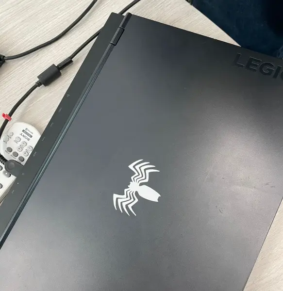
Final Application
Finally, the vinyl design was applied to a laptop surface.
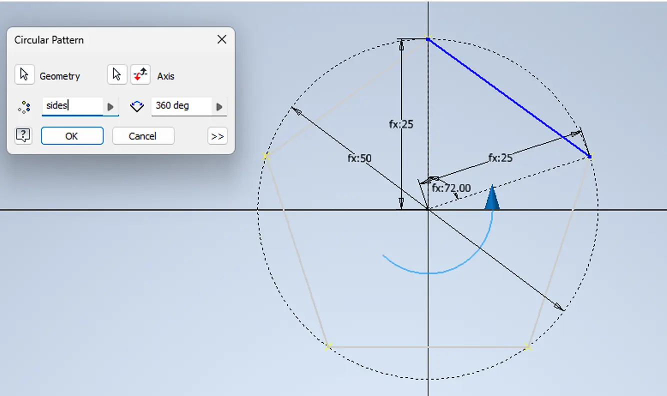
Parametric Polygon Design
At first, I assumed that a parametric design should be created directly as a solid. However, this approach is not suitable when the main goal is to modify the number of sides. For this reason, the entire design was developed at the sketch level.
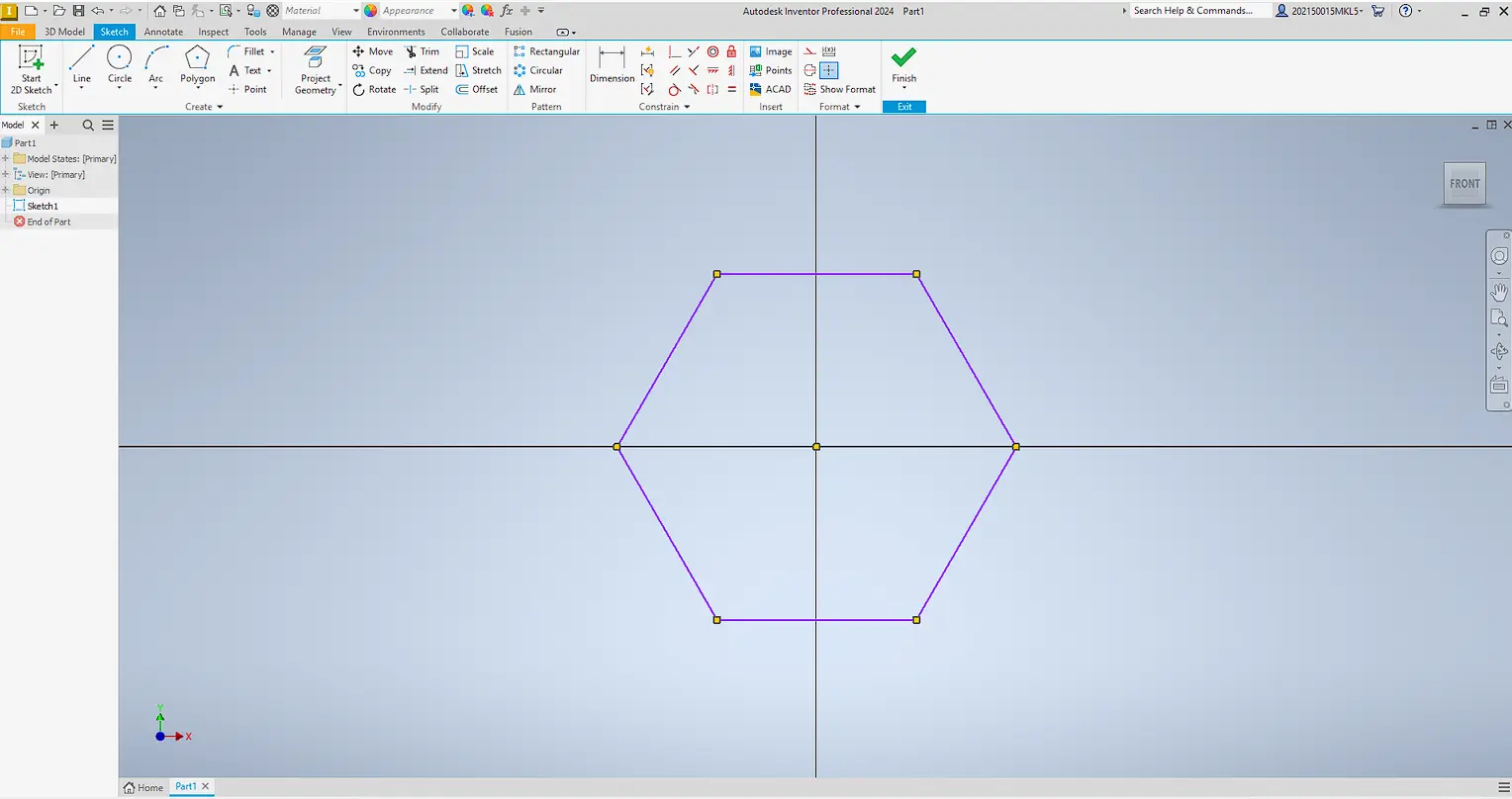
Instead of drawing the complete polygon, only one side of the geometry was modeled as a base module. By fully constraining this side, the polygon can be generated without redrawing geometry.
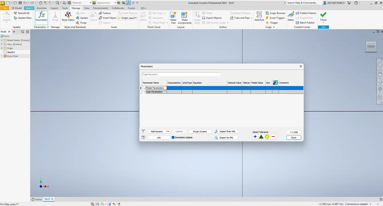
To control size, user parameters were created to define key dimensions and keep the sketch consistent.

A construction line was added as a reference axis, and the angle was defined with: 360° / number of sides.
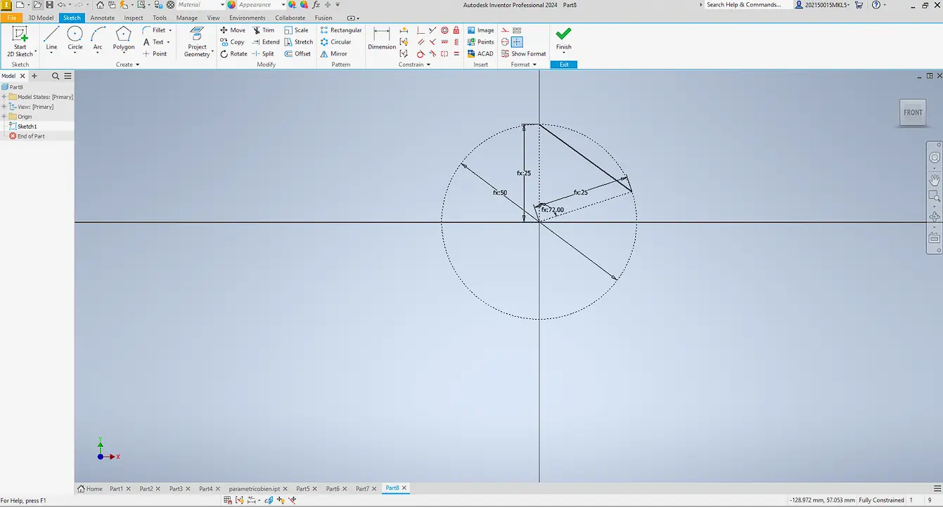
A circular pattern was applied around the sketch origin to replicate the side and generate the polygon.
Finally, an internal circular feature was added following the same parametric logic.
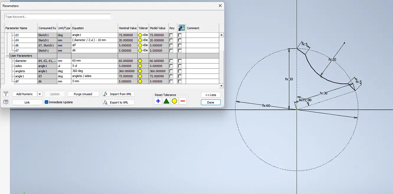
Parametric Design
The design was created using parametric modeling, allowing dimensions and joints to be modified dynamically. The MDF thickness was measured at 2.88 mm, so a tolerance value was added to improve the press-fit assembly and compensate for machining variations.
| Parameter | Description | Value | Unit |
|---|---|---|---|
| diameter | Overall diameter | 60 | mm |
| pattern | Repeated patterns | 9 | units |
| radius | Main radius | 30 | mm |
| dep | Slot depth | 7.5 | mm |
| width | Press-fit width | 2.48 | mm |
| tol | Press-fit tolerance | 0.4 | mm |
| chamfer | Chamfer size | 0.62 | mm |
MDF Cutting Process
The first step is to measure the material. In this case, I selected MDF. It is important not to fully rely on the supplier specifications, since materials often have a tolerance (± error). For this reason, I verified the thickness using a vernier caliper. Although the MDF was specified as 3 mm, the actual measured thickness was 2.88 mm. This difference is important because it directly affects press-fit joints and cutting accuracy in CNC machining.
.jpeg)
Next, the material is placed inside the cutting machine. At the same time, the tool must be positioned correctly, ensuring that the focal point is properly adjusted for accurate cutting. If the tool is too high or too low, it can be calibrated to achieve the correct cutting depth.
.jpeg)
Material placement inside the machine
.jpeg)
Tool positioning and calibration
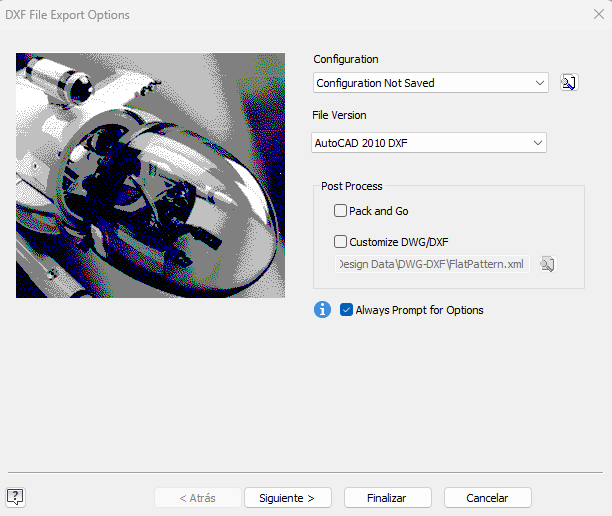
Design Import
Next, the design is imported in DXF format (2010 version) into the cutting software.
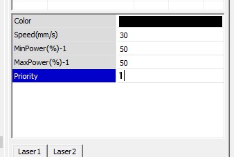
Machine Setup
Then, the cutting parameters are configured according to the material. In this case, the values used were Power: 50 and Speed: 30.
To optimize material usage, a simulation can be run to estimate how much material will be consumed. If adjustments are needed, the cutting position can be modified using the machine's arrow controls.
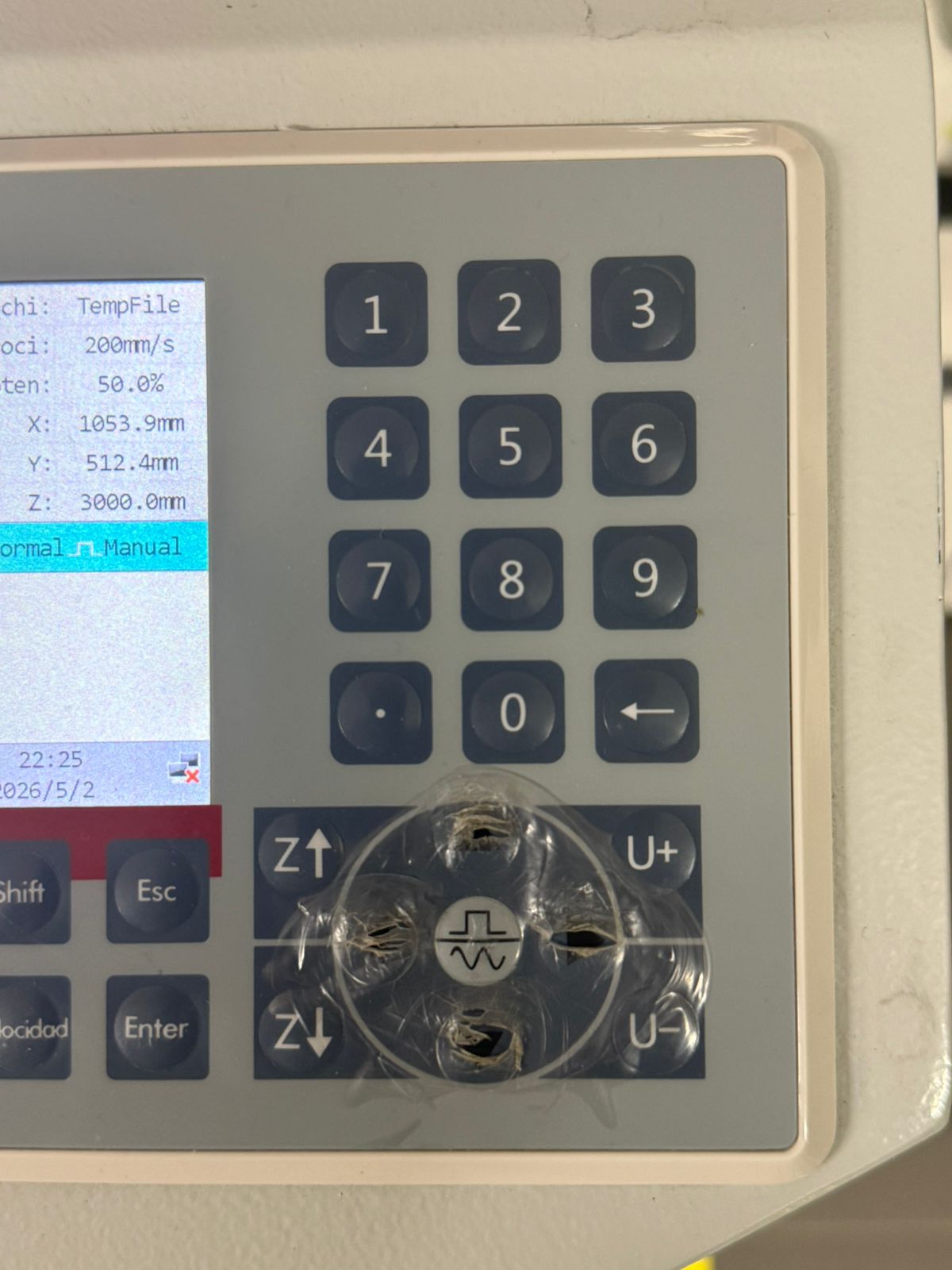
Position adjustment using machine controls
Simulation process
Cutting Process
Once the position is confirmed, the job is sent to the machine and the start button is pressed.
Simulation process
Final Result
After the cutting process is completed, the final pieces are obtained.
.jpeg)
Press-Fit Test
Finally, the pieces are tested to verify if the press-fit joints work correctly and fit tightly without additional support.
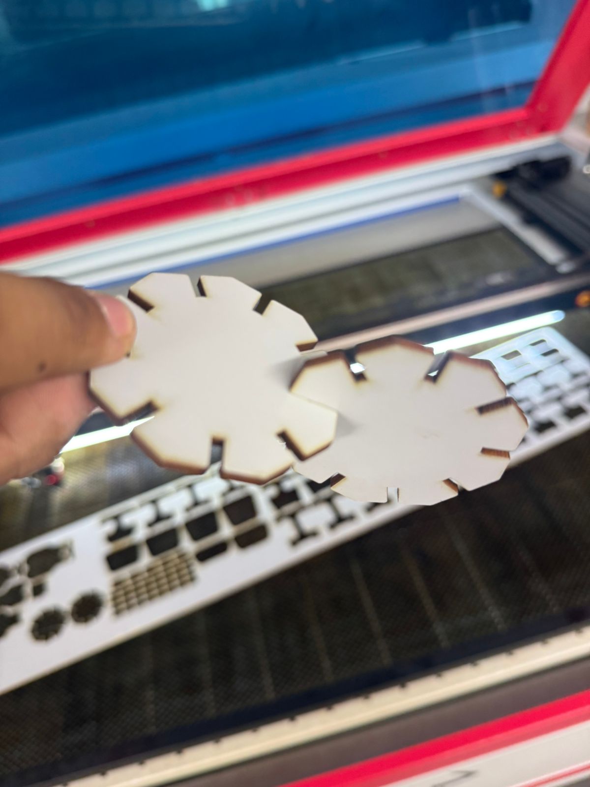
Reflection: Adjusting the cutting parameters and verifying material thickness are essential to achieve precise press-fit joints.
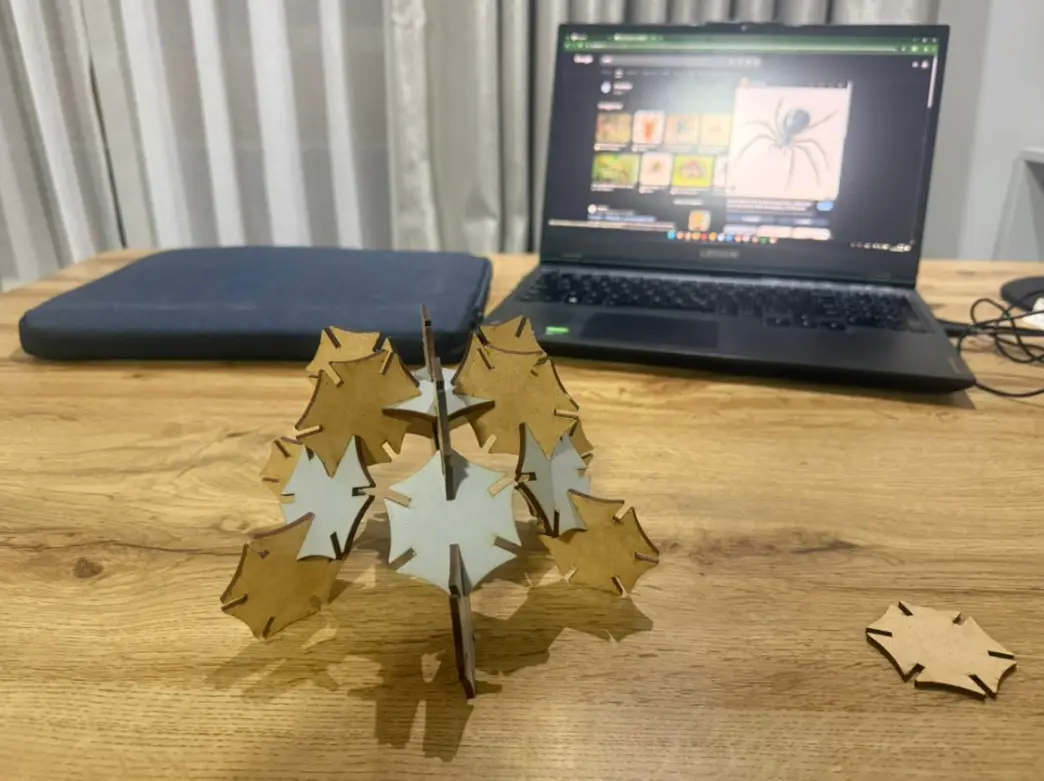
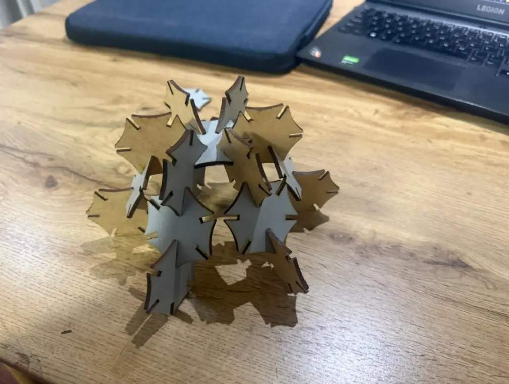
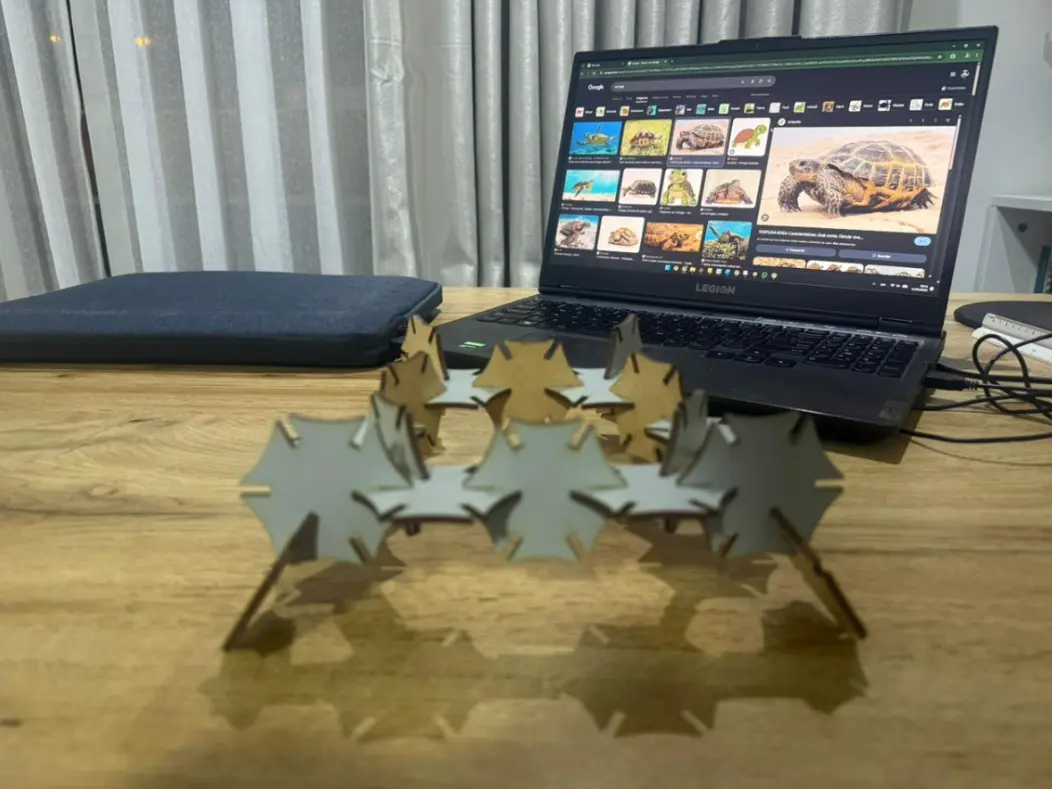
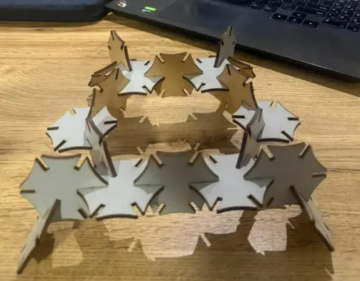
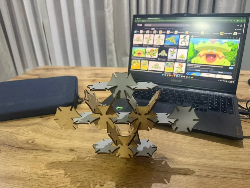
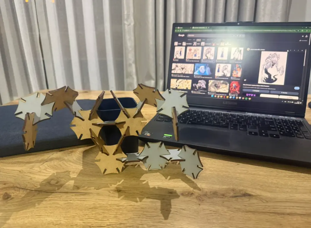
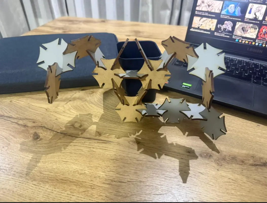
Structures Built with the 20-Piece Parametric Kit
Scorpion
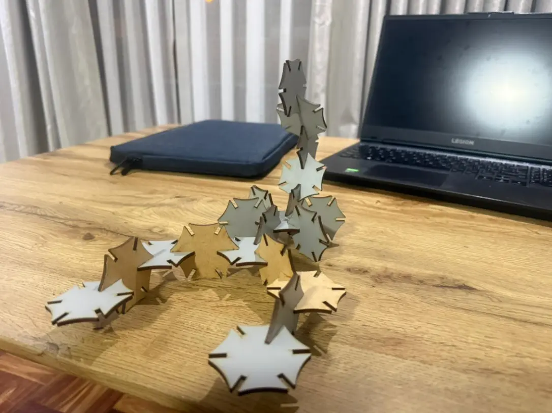
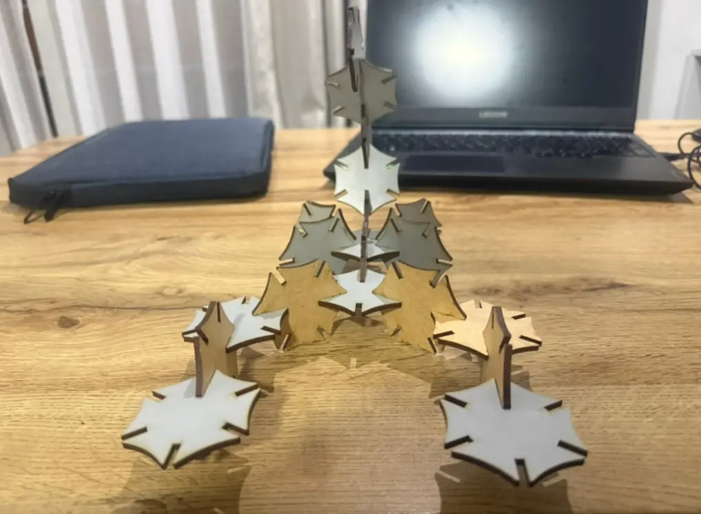
Black Widow Spider
Turtle
Pokémon (Maractus-inspired)
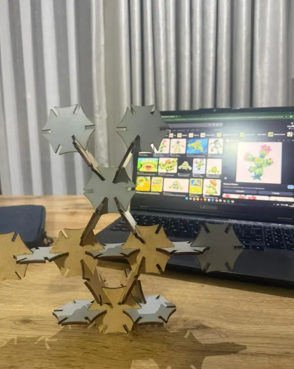
Pokémon (Ludicolo-inspired)
Rika Orimoto (Inspired Structure)