Assignments
Week 2 – Computer-Aided Design
Assignment
Checklist
- Model raster, vector, 2D, 3D, render, animate, simulate... a possible final project.
- Compress images and videos.
- Post a description with design files on the class page.
The goal of this week was to explore different design workflows and understand how each type of software contributes to the development of a complete project, from concept sketches to fabrication-ready models.
Design Workflow
To complete this assignment, I decided to use several software tools covering raster graphics, vector design, and 3D modeling. Each tool played a different role in my workflow, allowing me to move from initial ideas to technical models.
The software I used:
- Raster: GIMP, Krita, MyPaint
- Vector: Inkscape, Boxy Svg
- 3D Modeling: Autodesk Inventor, Fusion 360
Raster tools were used for conceptual sketches and visual exploration.
Vector tools helped me create precise 2D drawings for fabrication.
Finally, Inventor was used to model the main components of my final project in 3D.
2D – Raster Design
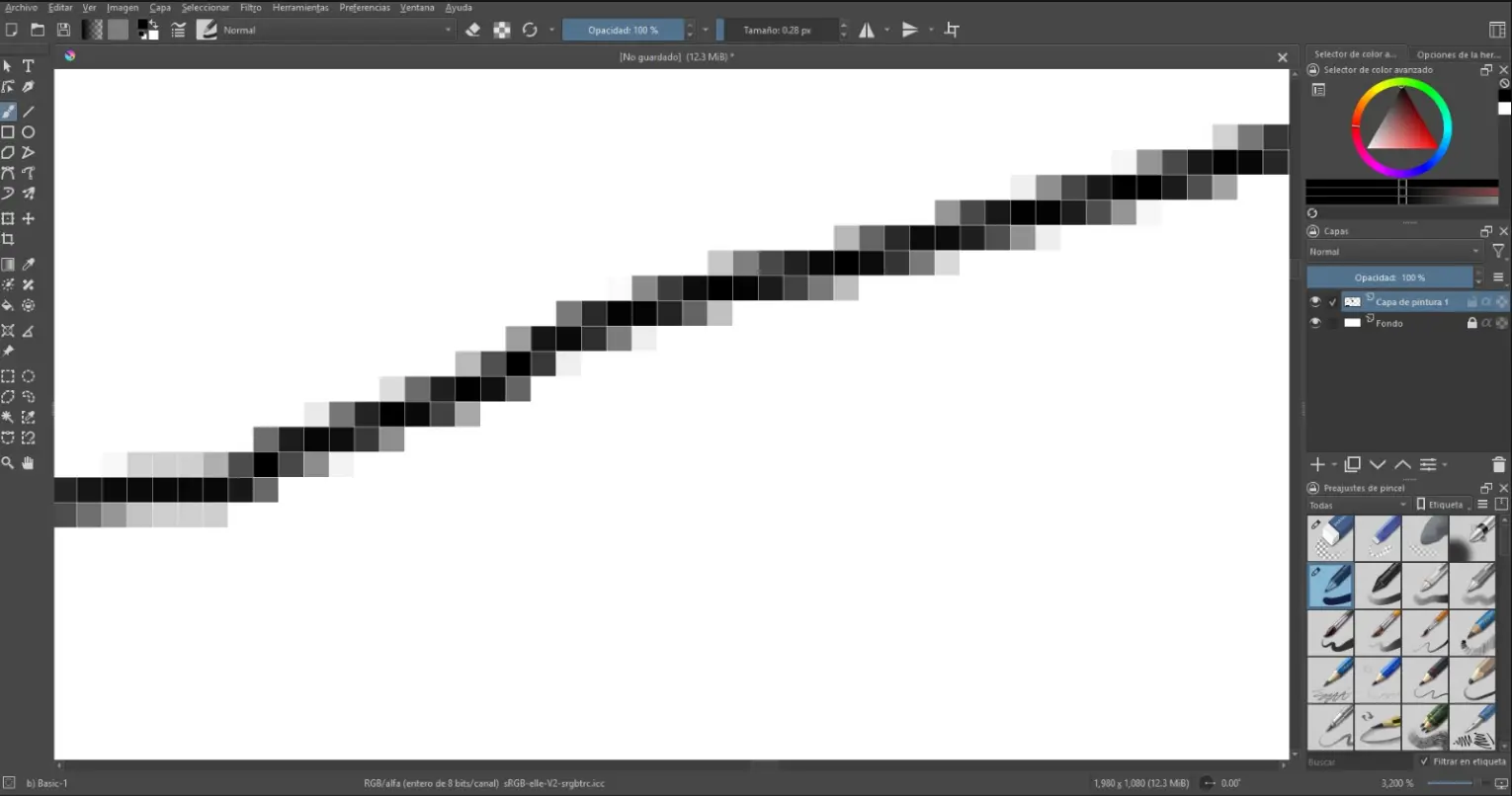
Raster graphics are images made of pixels (small colored squares). Each pixel contains color information, and together they form an image. Because raster images depend on resolution, they lose quality when they are scaled up.
For this part of the assignment, I based my raster work on my final project concept, using three different software tools: GIMP, Krita, and MyPaint. Each program helped me explore my design in a different way. I used them to sketch the tentacle shape and develop visual ideas for my robotic arm. This process allowed me to compare workflows.
Inspiration
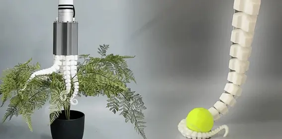
This image was one of my main sources of inspiration for my final project. I was especially interested in the flexible robotic tentacle and its ability to adapt to different objects and surfaces. This concept influenced the design of my Octohand project, particularly the idea of creating a soft and articulated structure capable of gripping objects in a gentle and adaptive way.
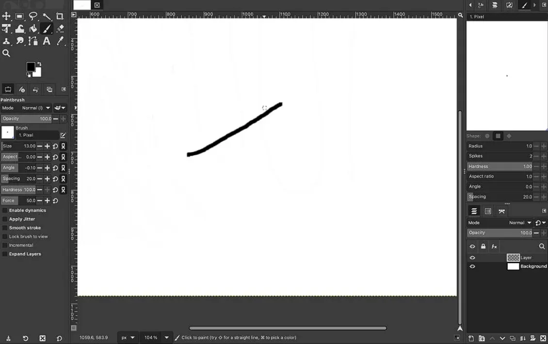
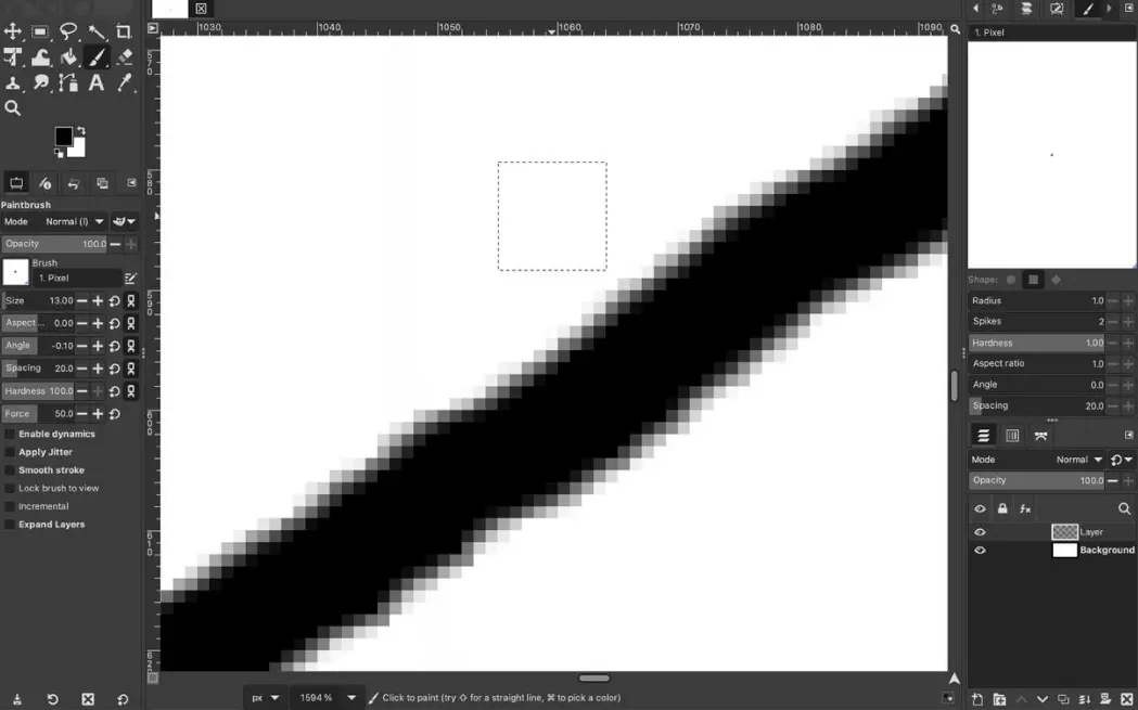
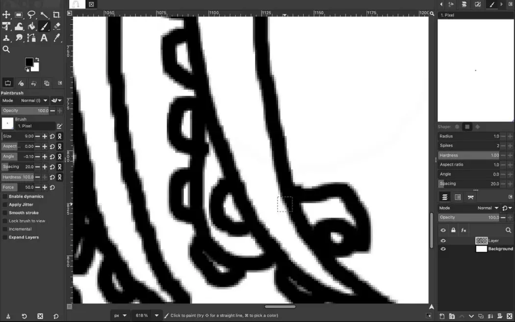
GIMP
I used GIMP to create and edit raster images. This software helped me adjust contrast, crop images, and prepare visual references for my project documentation.
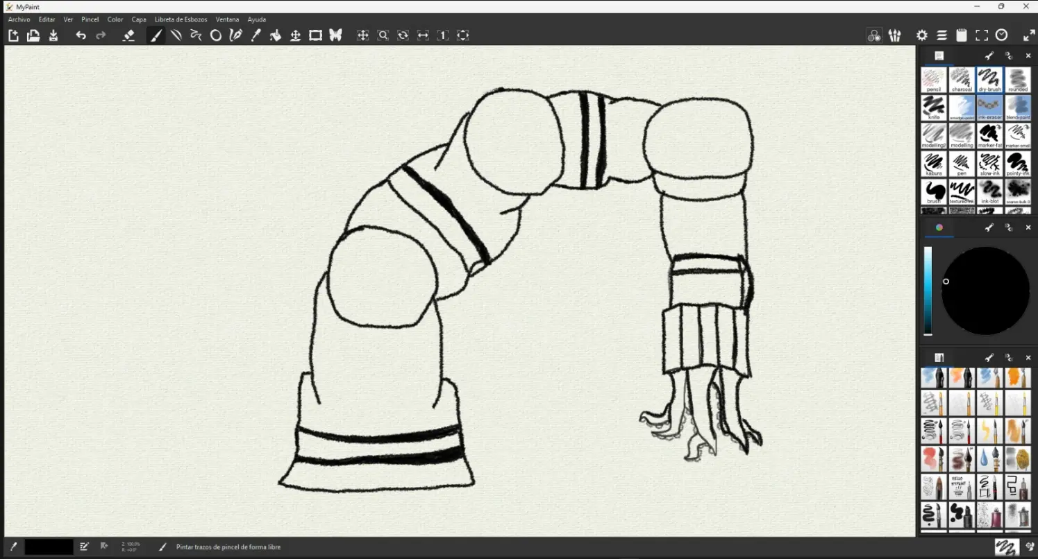
Krita
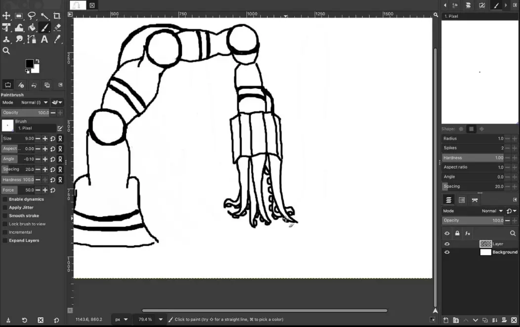
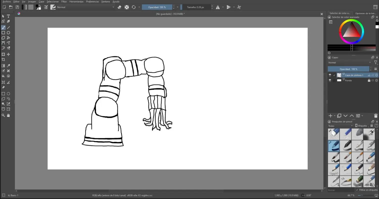
Krita was mainly used for sketching initial concepts of my final project. Its brush tools allowed me to draw freely and explore different shapes for the tentacle and gripper design.
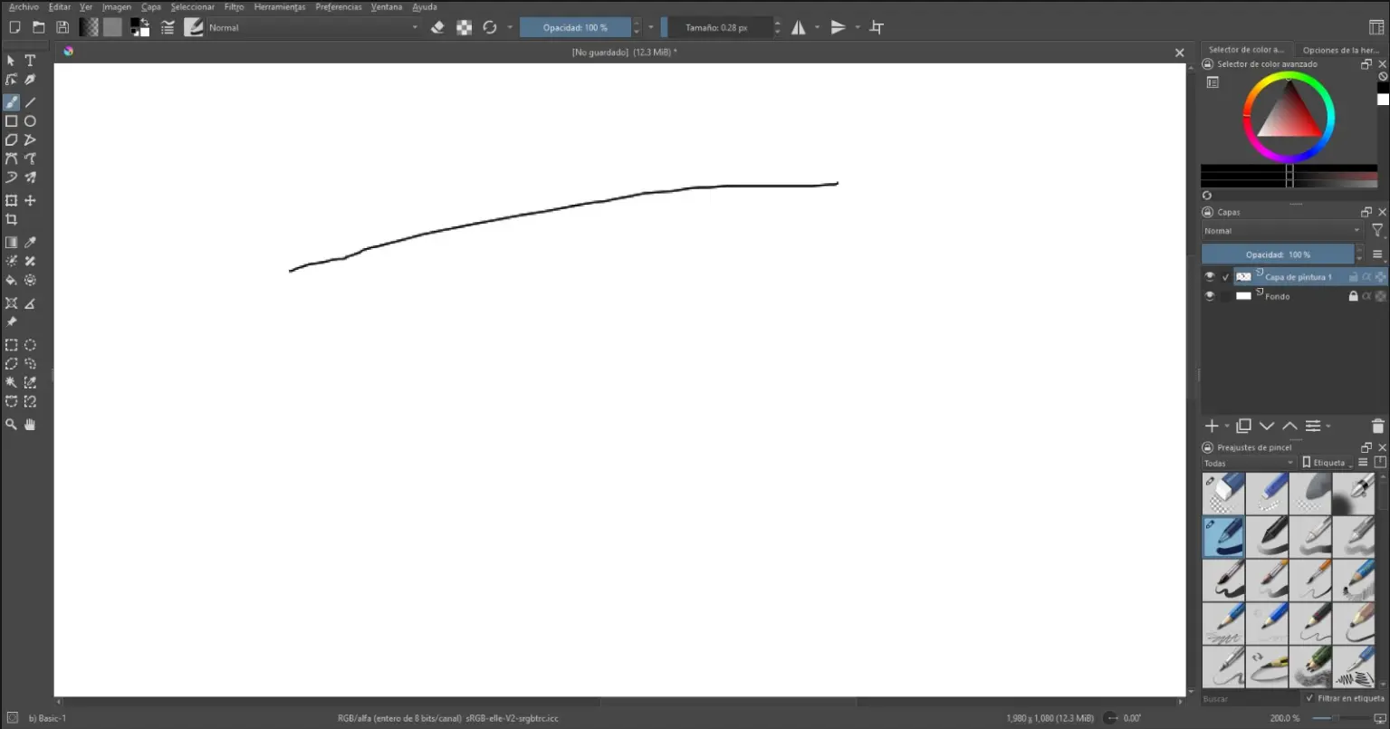
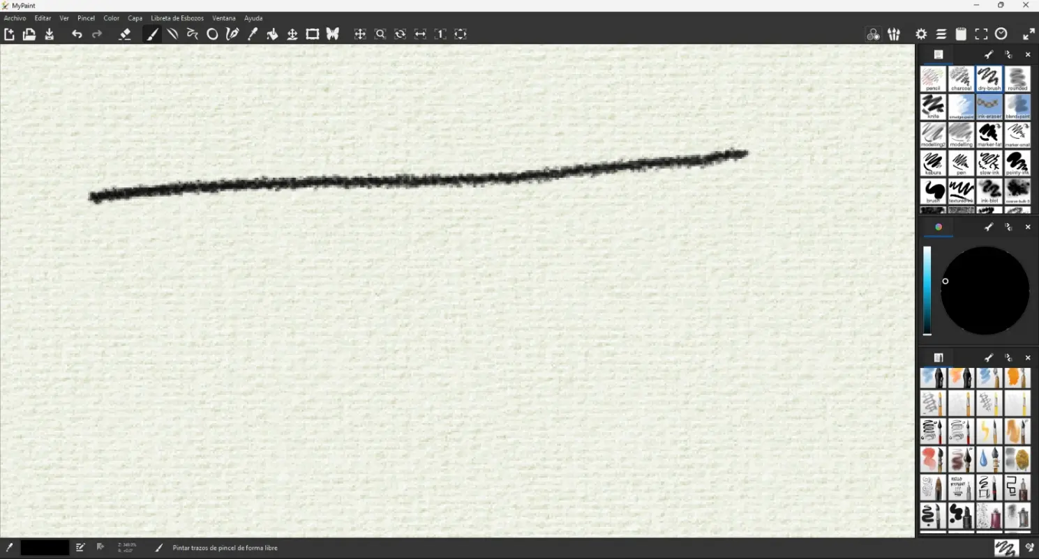
MyPaint
MyPaint was used for quick hand-drawn ideas and early conceptual drawings. It allowed me to focus on shapes and movement without distractions from complex tools.
GIMP helped me clean my sketches by increasing contrast and removing unnecessary background, making the lines clearer before moving to vector and 3D modeling. It was also useful to organize reference images for my robotic arm and tentacle design.
2D – Vector Design
Vector graphics are based on mathematical paths instead of pixels. This means they can be scaled infinitely without losing quality.
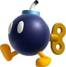
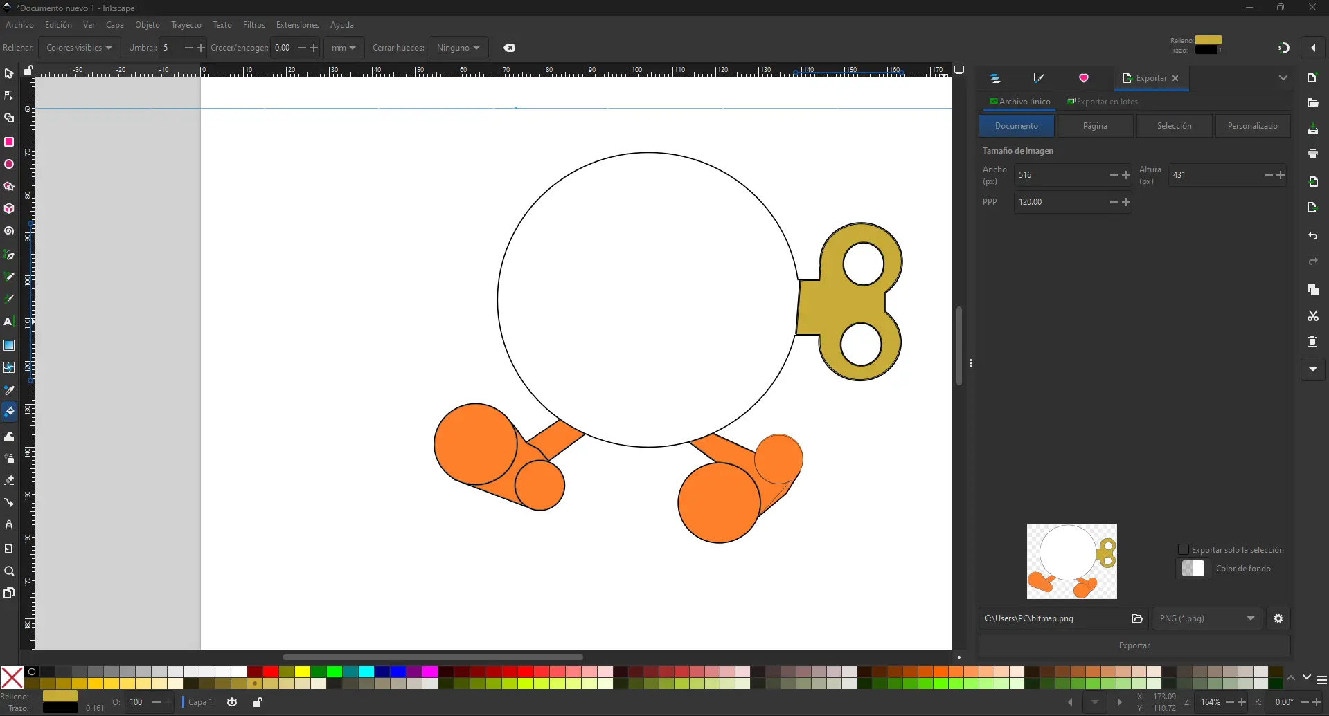
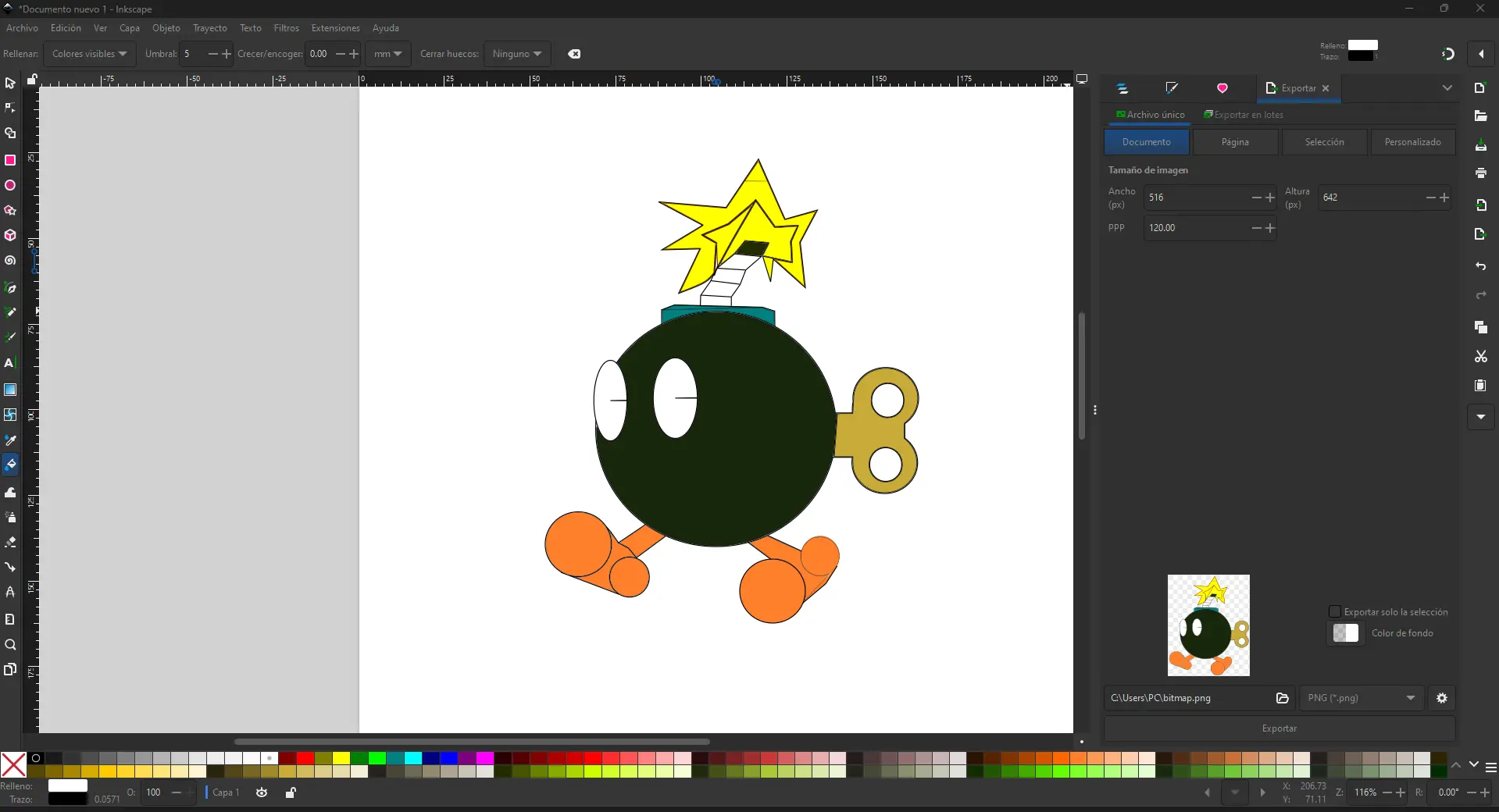
For the vector design, I took inspiration from the Bomb character from Mario Bros. I used Inkscape to recreate the character using basic geometric shapes such as circles and paths. This helped me practice clean vector drawing while keeping the process fun and creative. Through this exercise, I learned how to combine shapes and apply colors.
Inkscape
Inkscape was used to convert sketches into vector drawings. I created clean outlines and exported SVG files that can later be used for laser cutting or vinyl cutting.
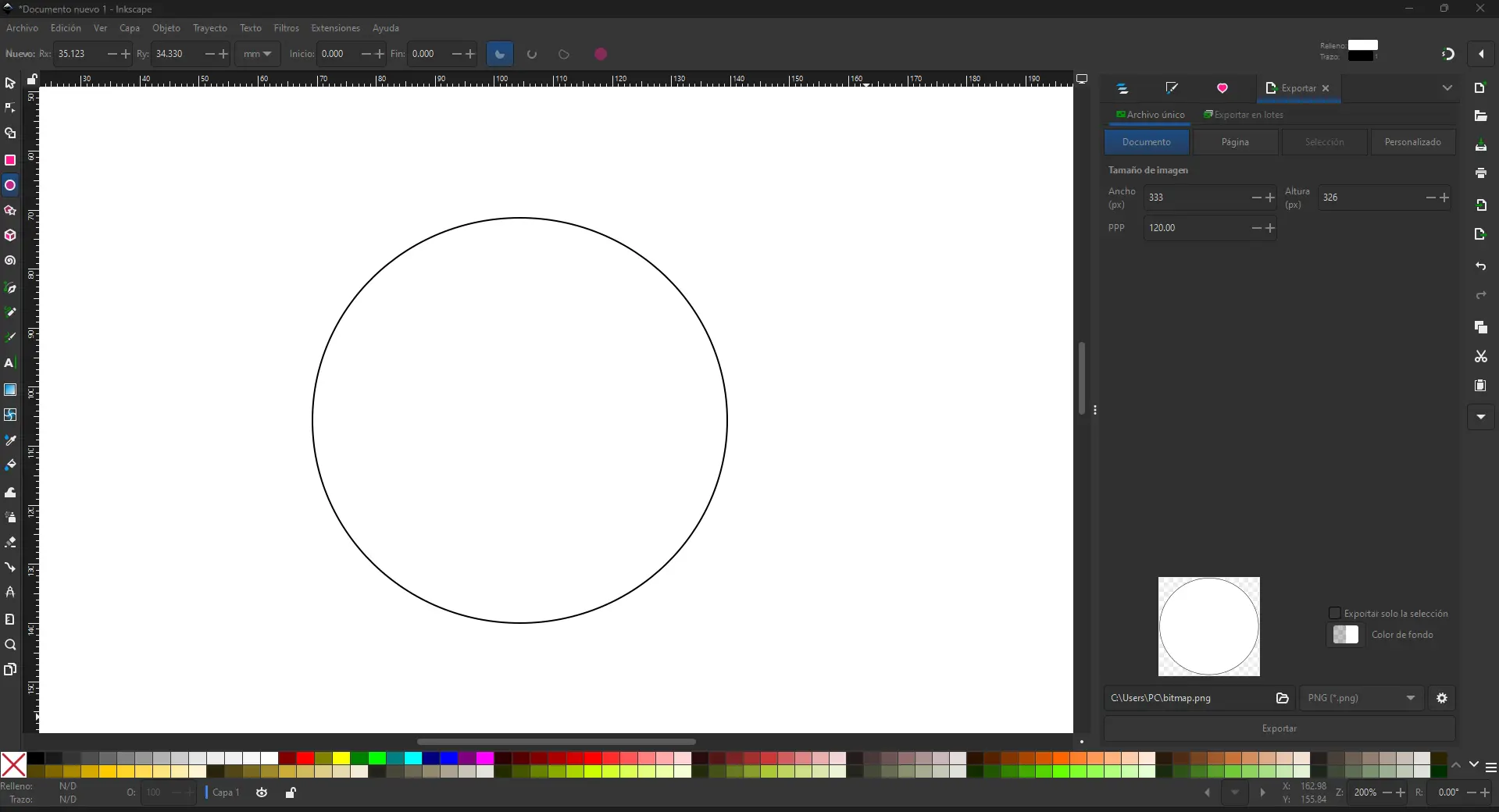
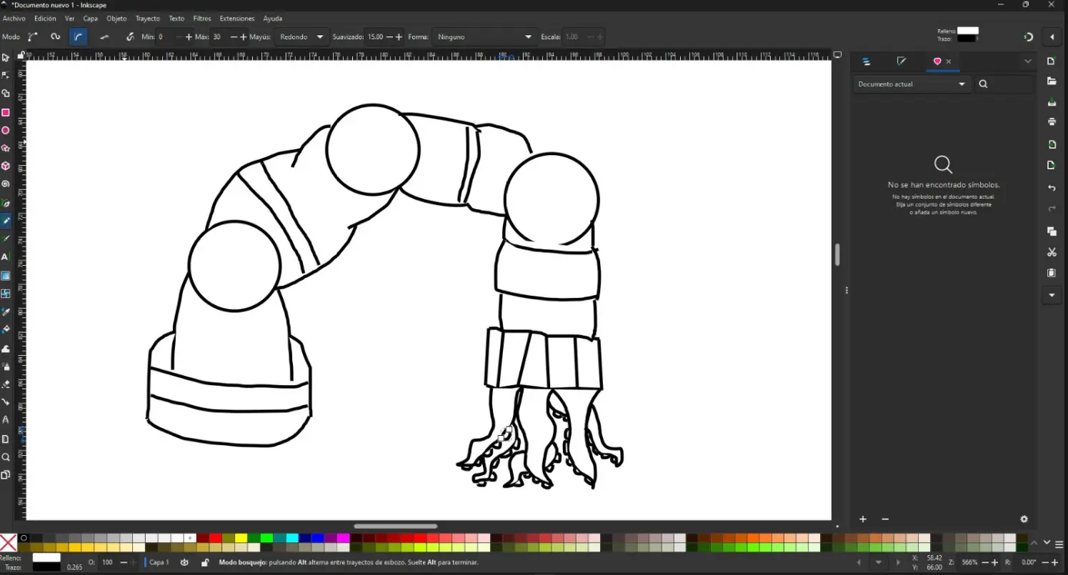
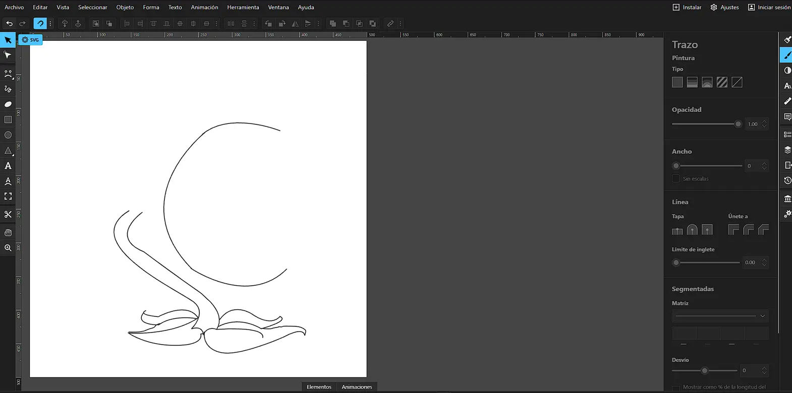
Freehand Drawing in Inkscape (Final Project Test)
I used Inkscape to create a freehand vector sketch of my final project concept. This drawing was made as an early visual test to explore the shape, articulation, and proportions of the robotic tentacle before moving to parametric and 3D modeling.
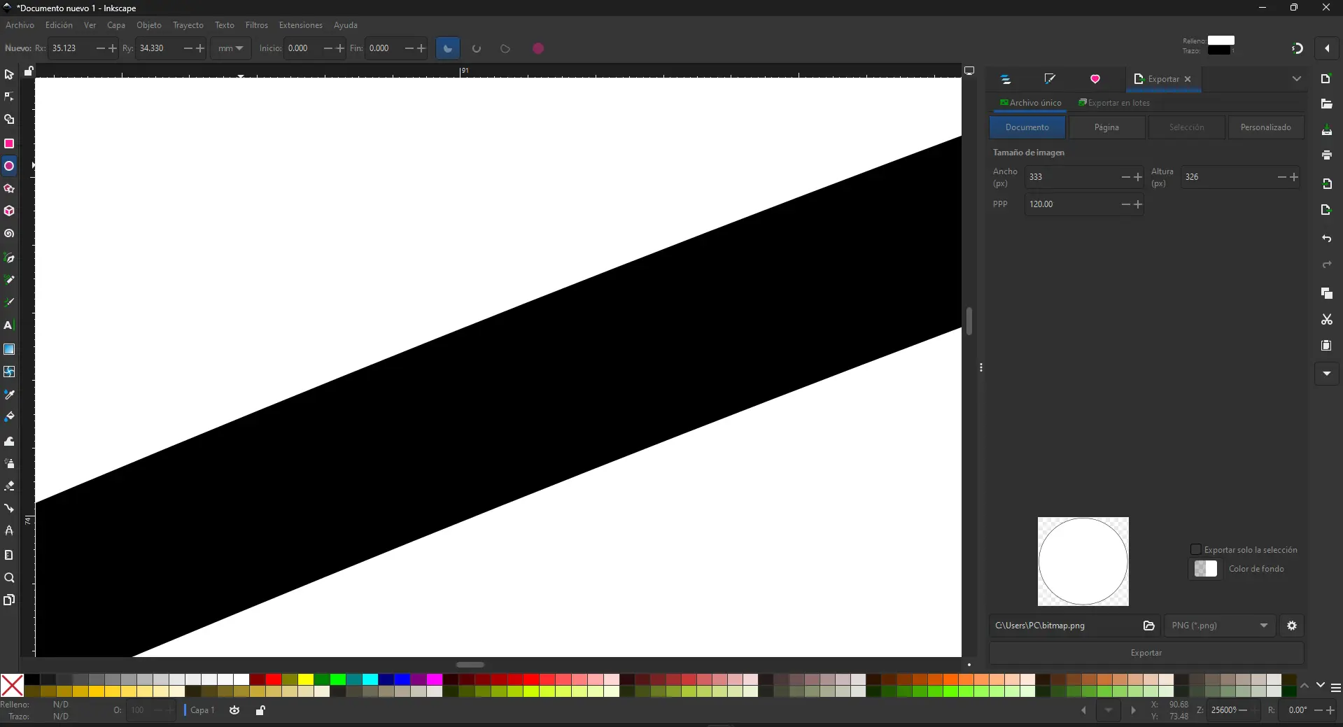
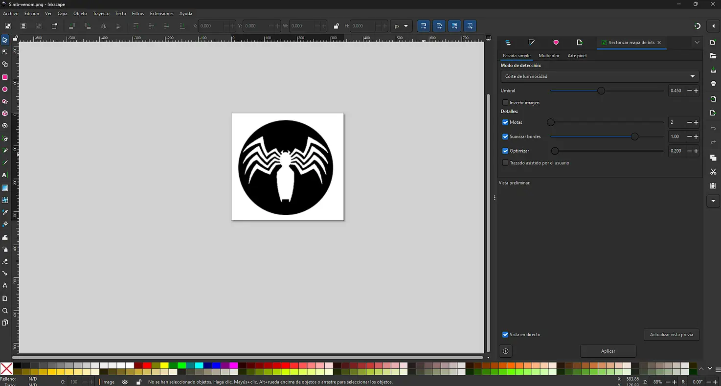
Vectorizing an Image (Trace Bitmap)
In Inkscape, I used the Trace Bitmap feature to convert a raster image into an editable vector. This is useful to create clean outlines for fabrication (laser/vinyl) and to scale graphics without losing quality.
Process
- I imported the raster image into Inkscape (File → Import) and selected it.
- Then, I opened the vectorization tool: Path → Trace Bitmap. Depending on the image, I used Single scan for black-and-white silhouettes.
- After clicking Apply, Inkscape generated a new vector object on top of the original image. I moved the vector aside to compare both results, and deleted the raster version.
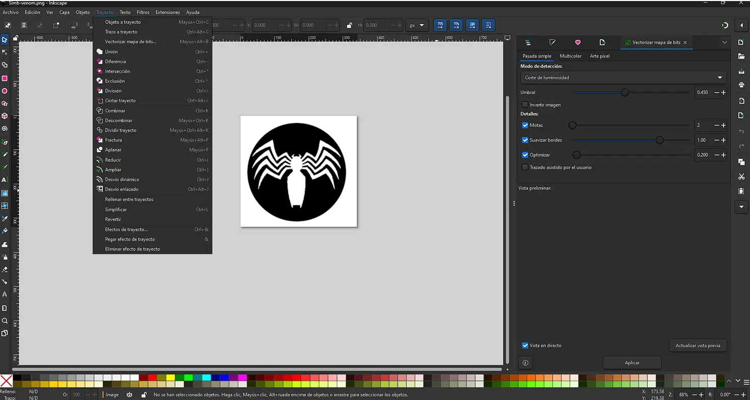
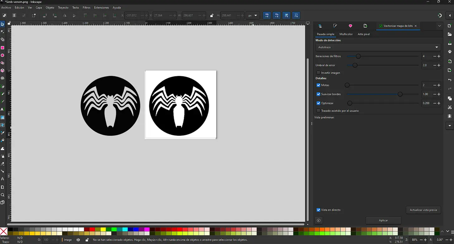
Finally, I refined the vector by editing nodes with the Node tool and removing any unwanted shapes.
Boxy SVG
Boxy SVG is a vector graphics editor focused on working directly with the SVG (Scalable Vector Graphics) format. It allows creating and editing vector illustrations using paths, strokes, and fills, making it suitable for web graphics, laser cutting, and digital fabrication workflows.
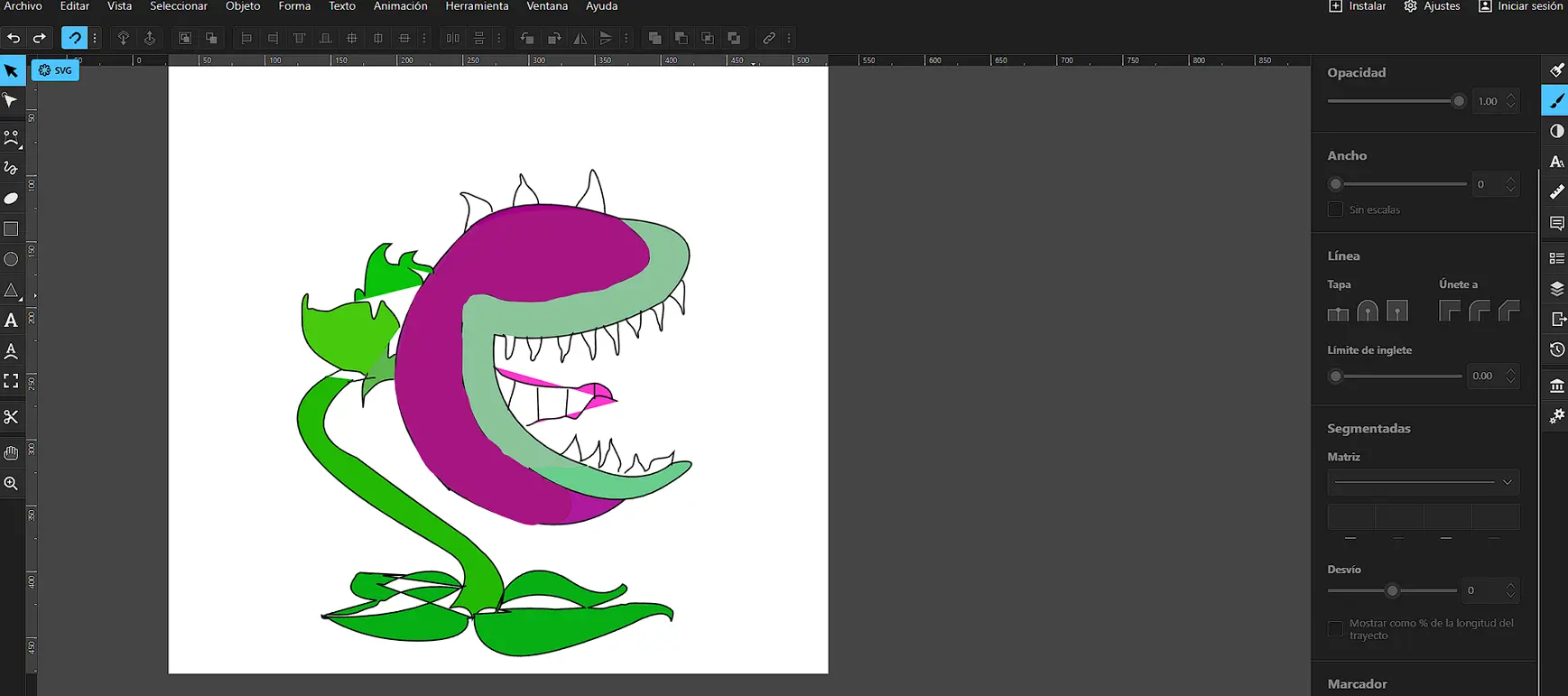
My experience using Boxy SVG was initially stressful. I was not familiar with the software and did not follow tutorials or guides. I started drawing only with the knowledge I already had, exploring the interface through trial and error.
As I continued working, I became more comfortable with the drawing mechanics. I focused on completing the outline and understanding how strokes and paths behaved while building the character shape.
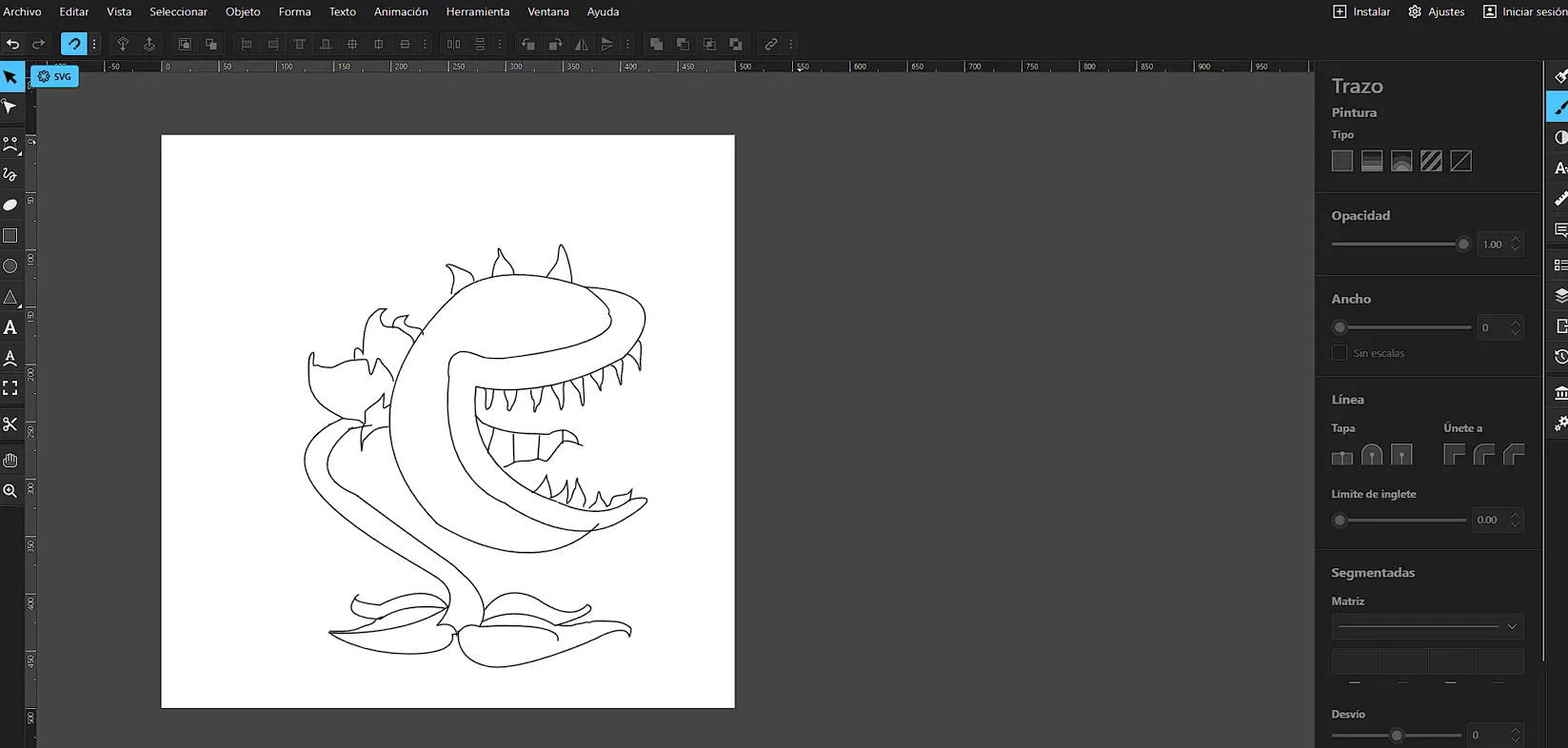
When I started painting the illustration, I noticed that only certain areas could be filled. Boxy SVG detected only some parts as closed shapes, while other areas were not fully closed paths and therefore could not be filled automatically.
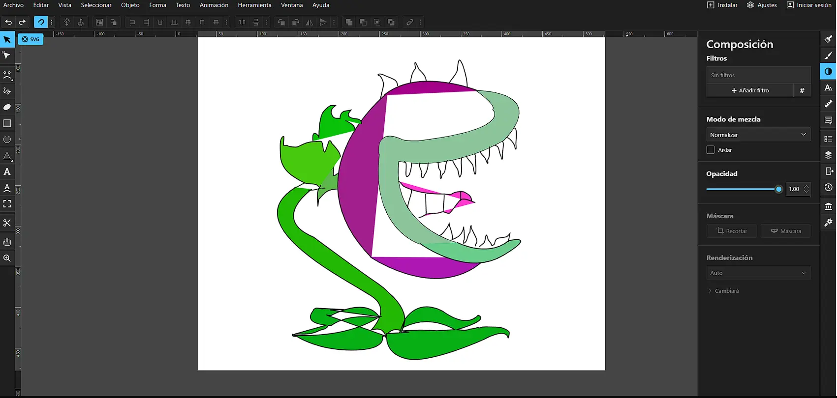
Because of this limitation, I decided to paint the drawing manually. Although this process was slower, it helped me better understand how vector software interprets geometry and the importance of properly closed paths.
3D – Modeling
3D modeling is the process of creating digital objects with width, height, and depth. It allows visualizing, modifying, and testing designs before fabrication.
Autodesk Inventor
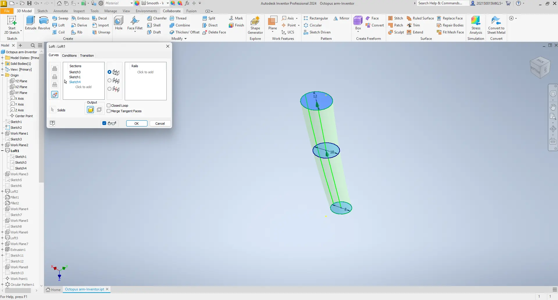
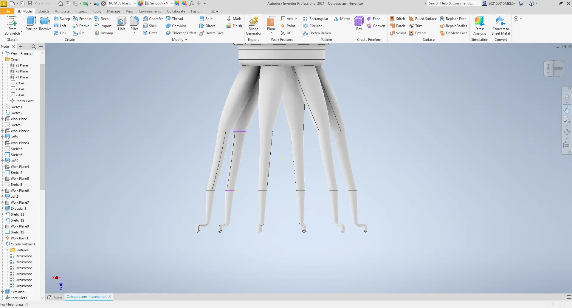
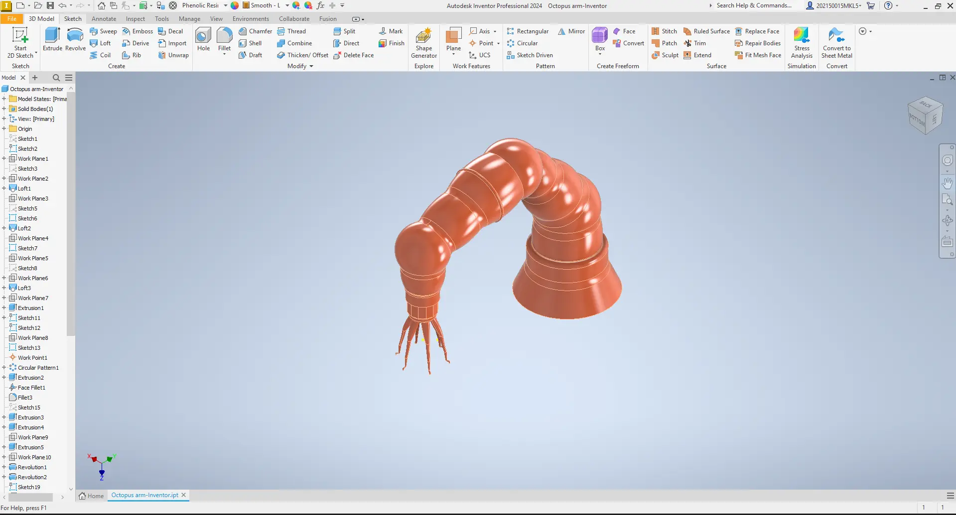
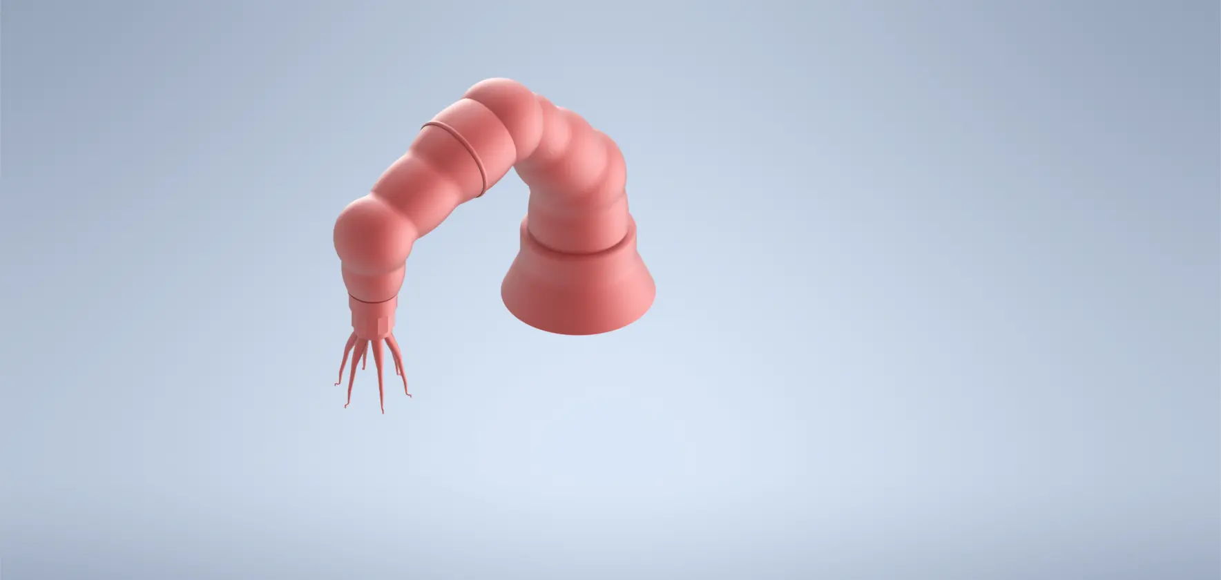
Autodesk Inventor was used to create parametric 3D models of my final project, focusing on the tentacle structure.
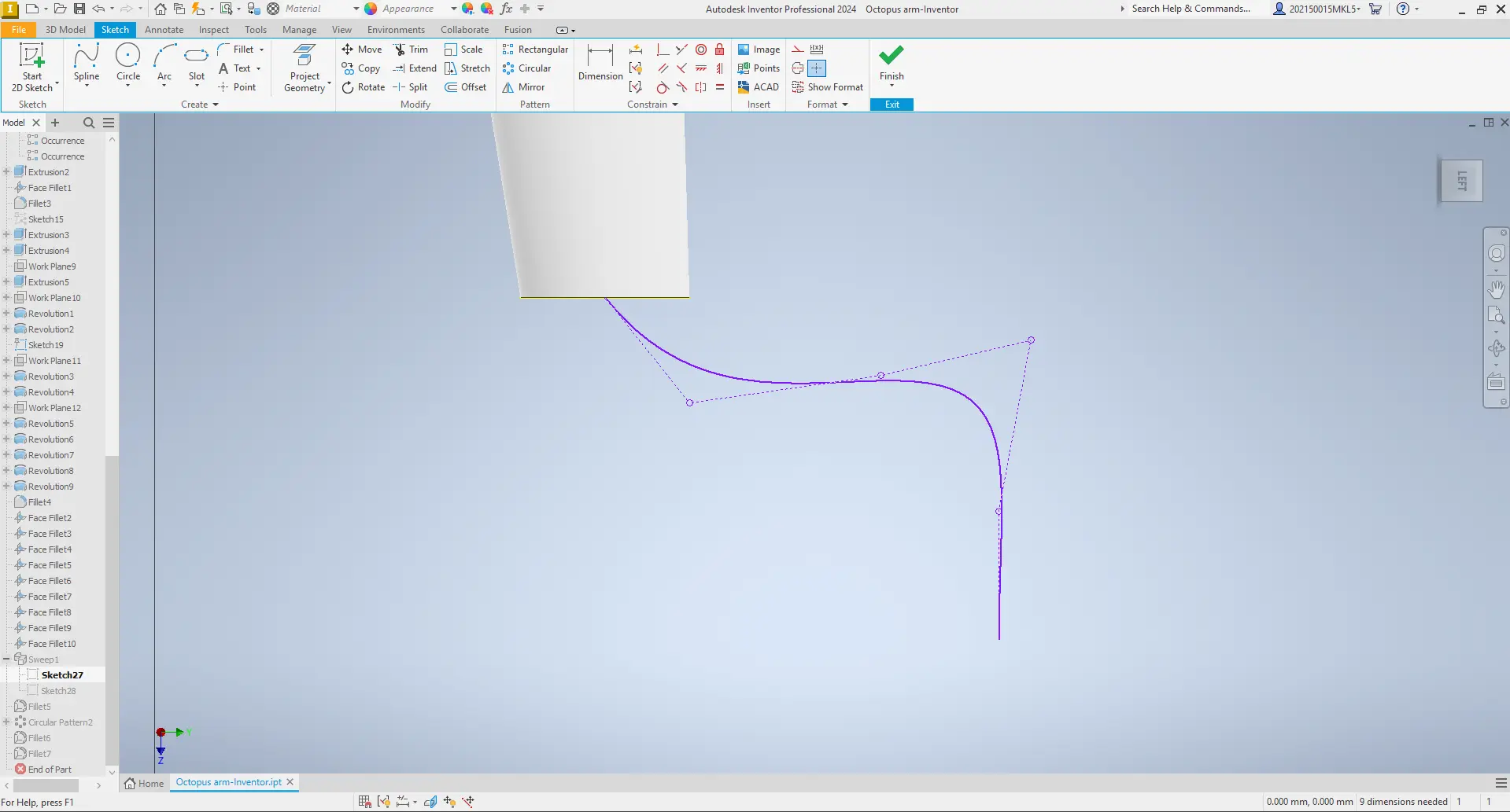
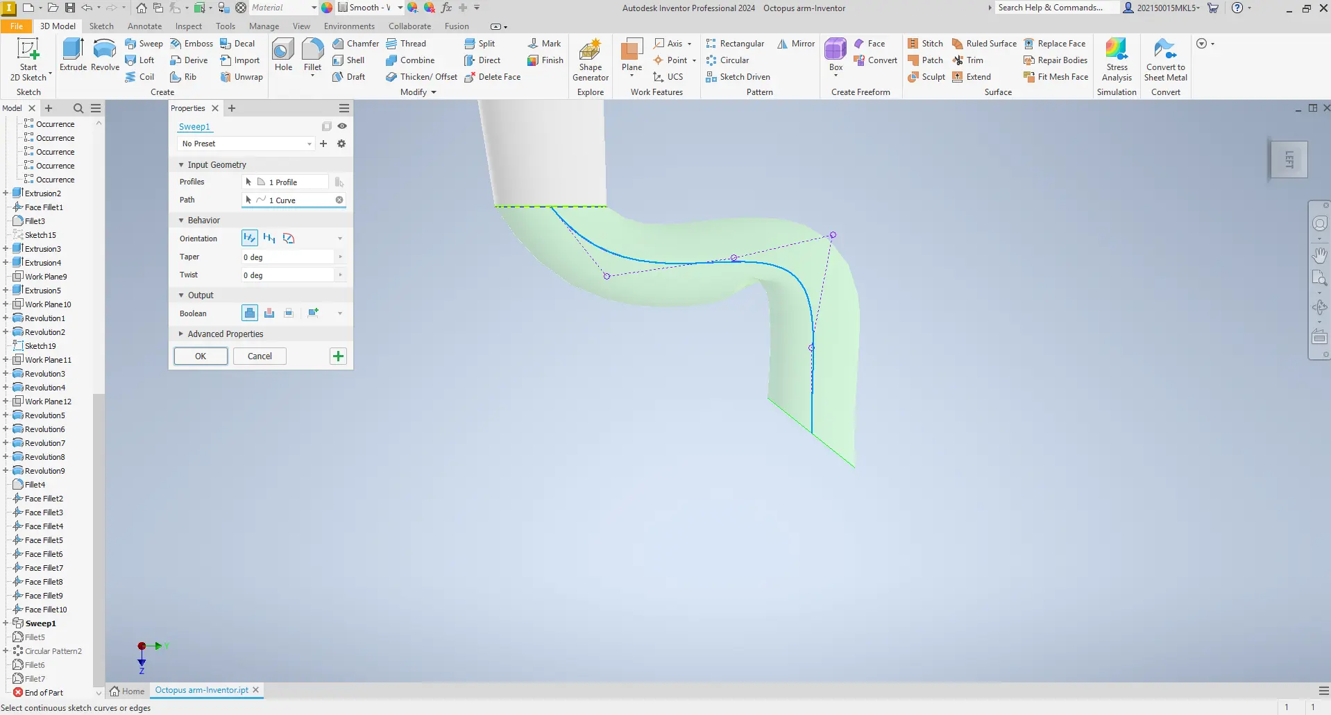
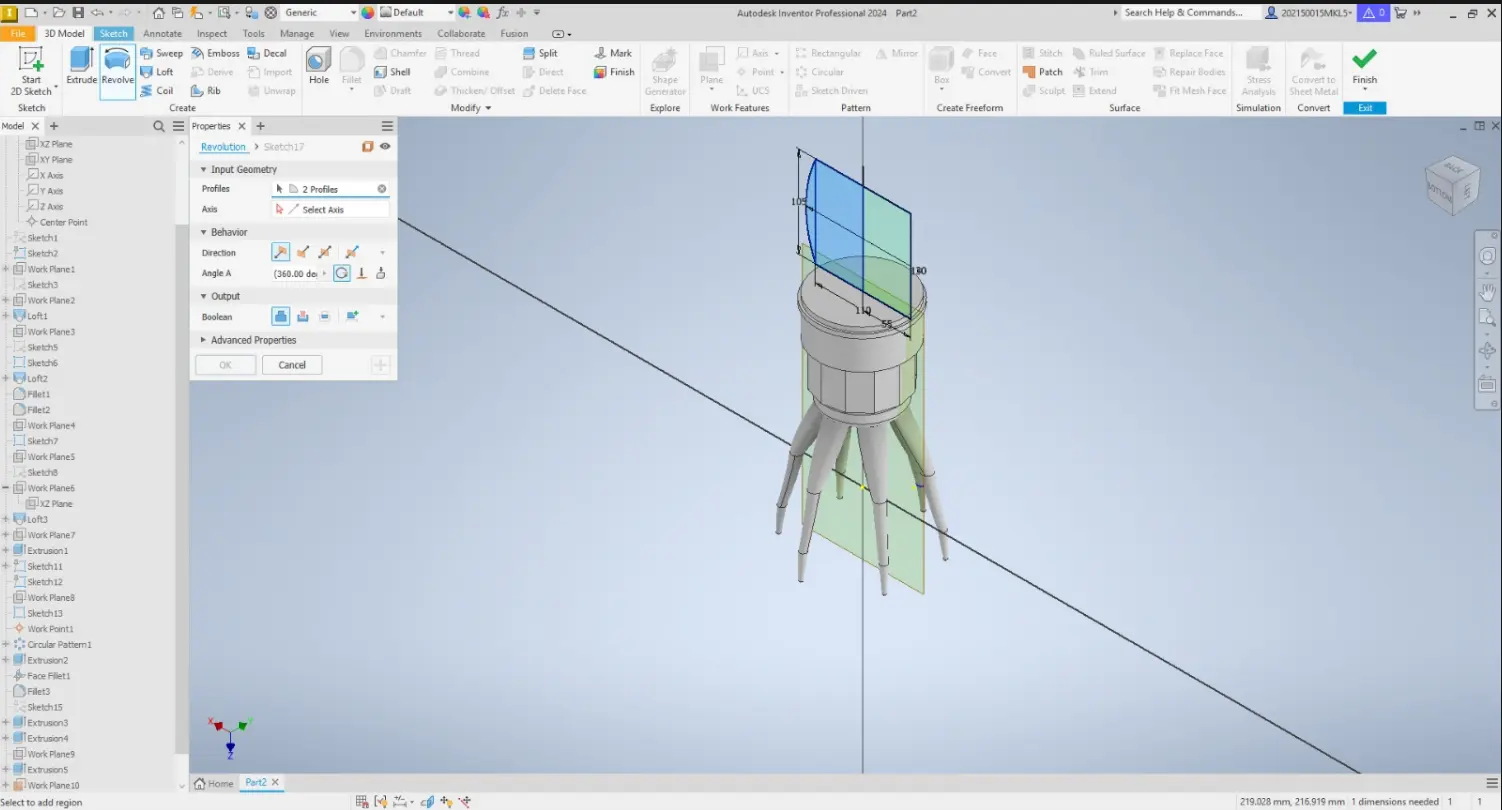
Inventor allowed me to adjust dimensions easily and create new reference planes to modify different parts of the octopus arm. I also used tools such as Loft and Sweep to generate organic shapes for the tentacle.
Through this workflow, I learned to combine sketches, planes, Sweep, Loft, and basic parametric tools. Most of the process involved trial and error, adjusting curves and dimensions until the tentacle achieved the desired flexibility and shape.
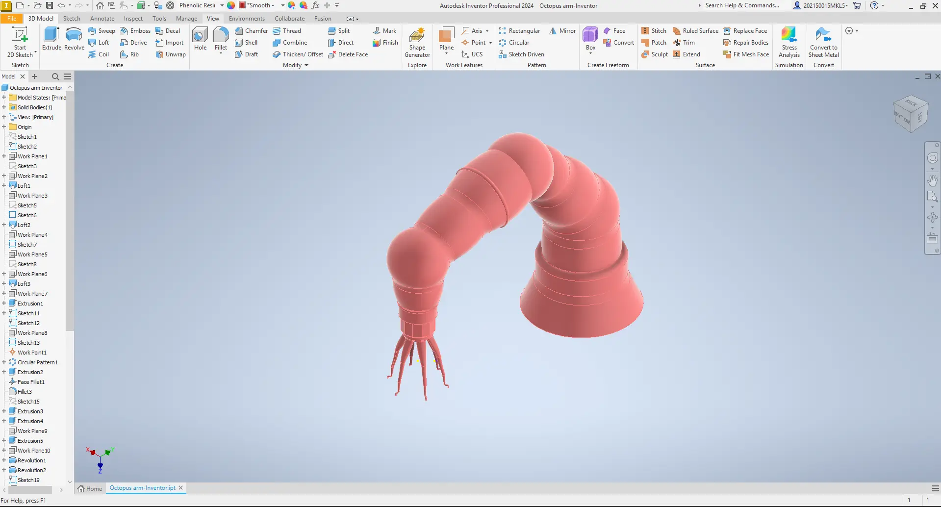
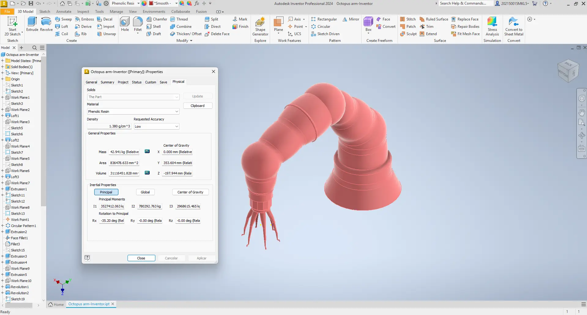
Applying Materials and Textures
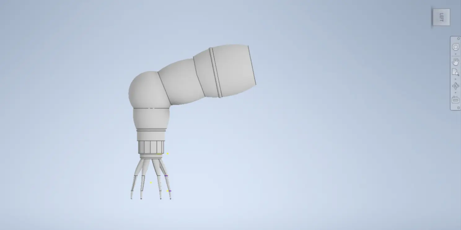
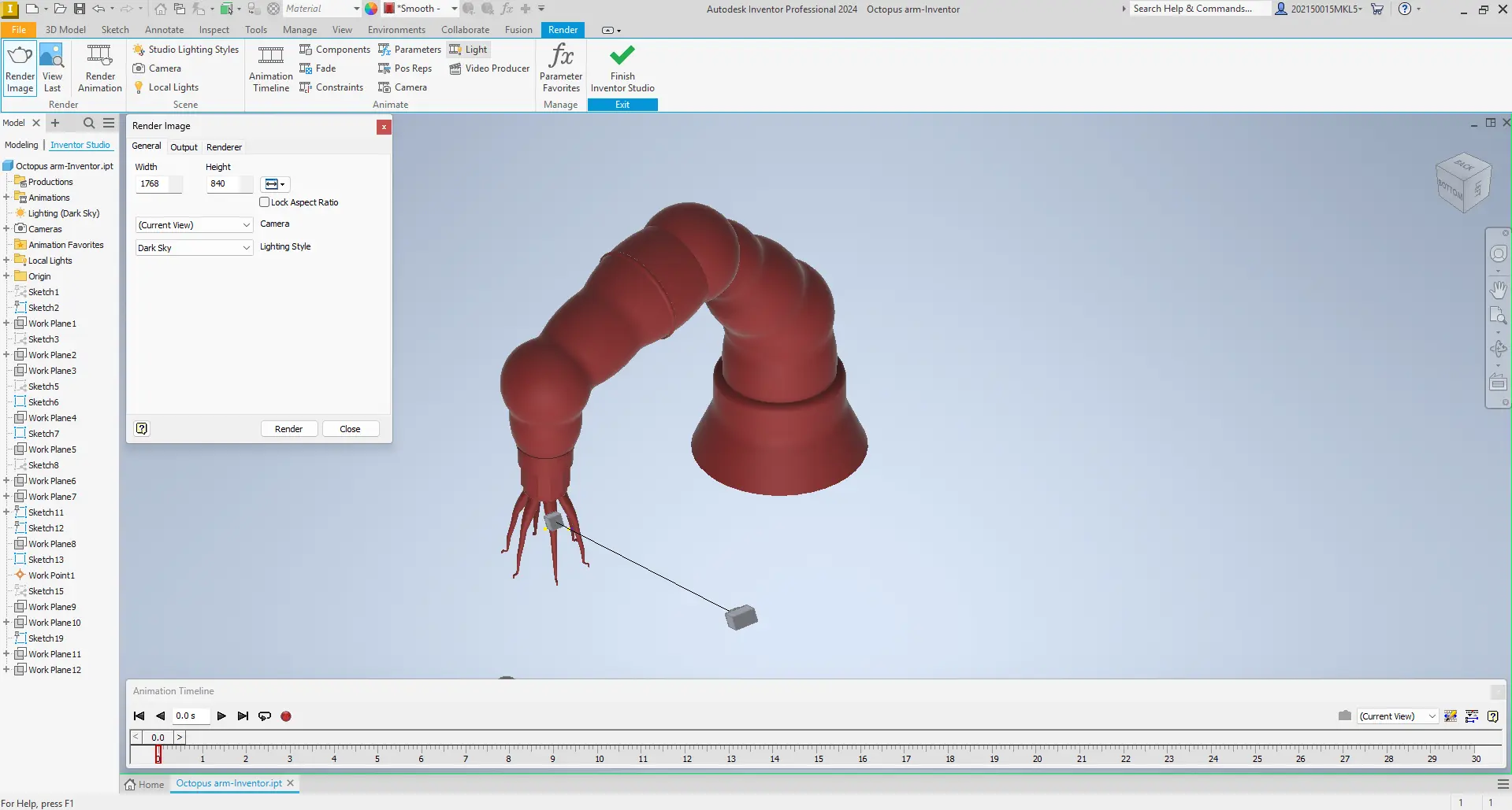
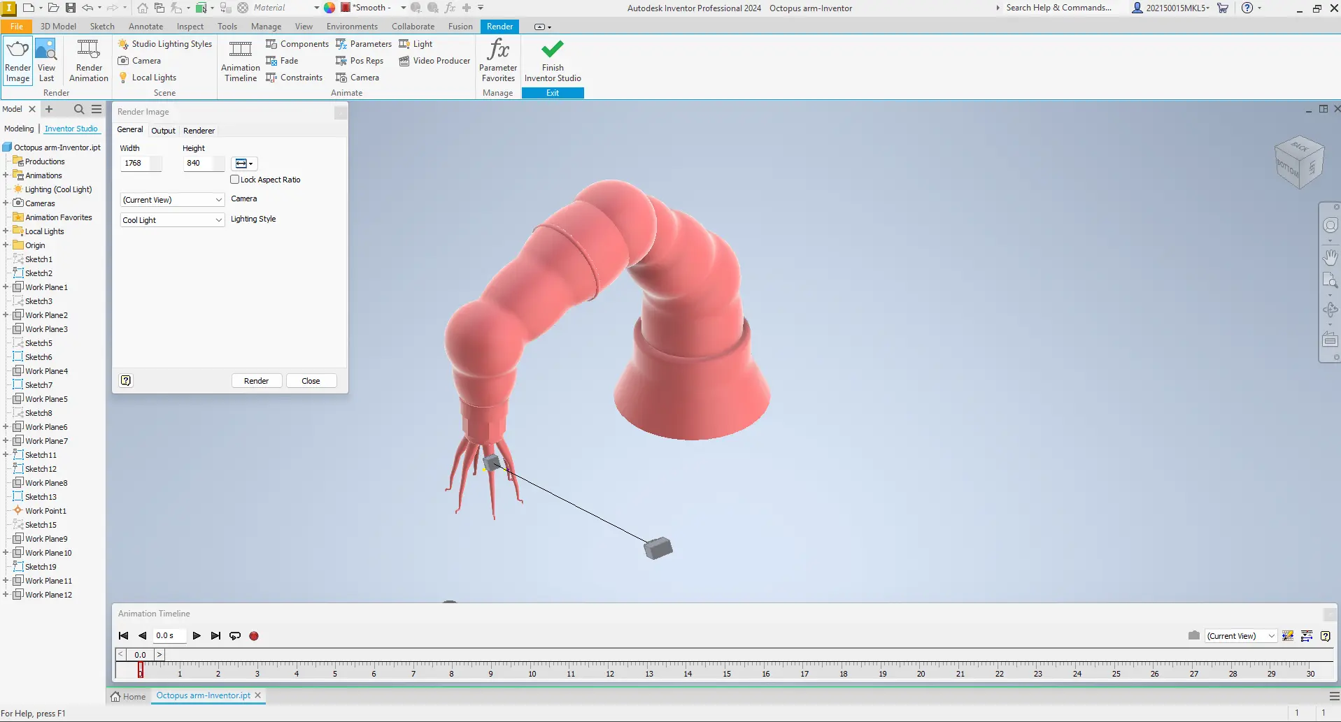
At this stage, I experimented with different materials and surface appearances in Autodesk Inventor to visualize how the tentacle could look in real life. I explored the built-in material library, testing several smooth and colored finishes to better understand how surface properties affect the perception of form and volume.
By applying different materials directly to the model, I could quickly compare visual results and see how light interacts with curved surfaces. This helped me choose a better visual finish for my final project.
This process also helped me learn how to assign materials to individual parts through trial and error until achieving a more consistent look.
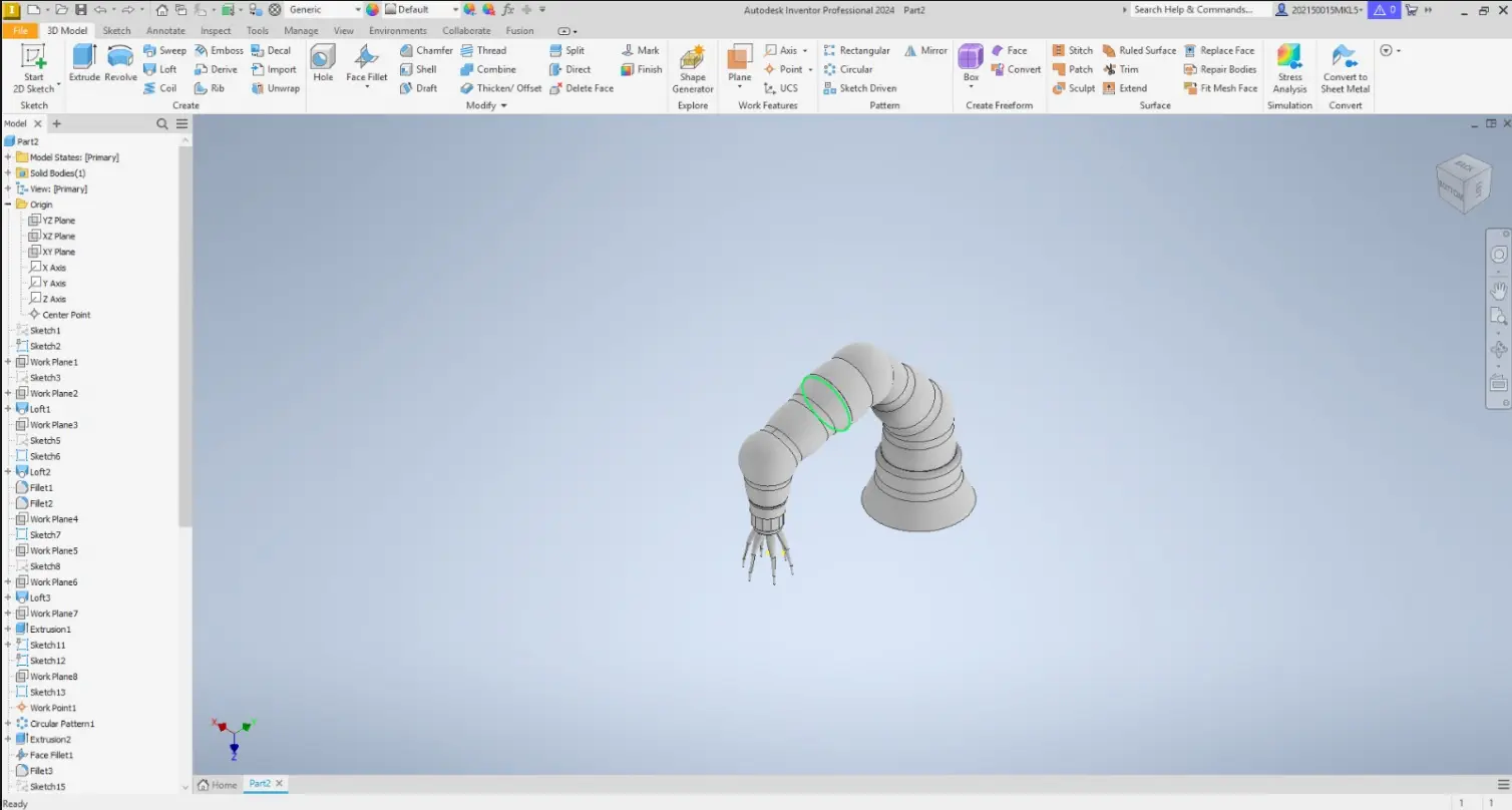
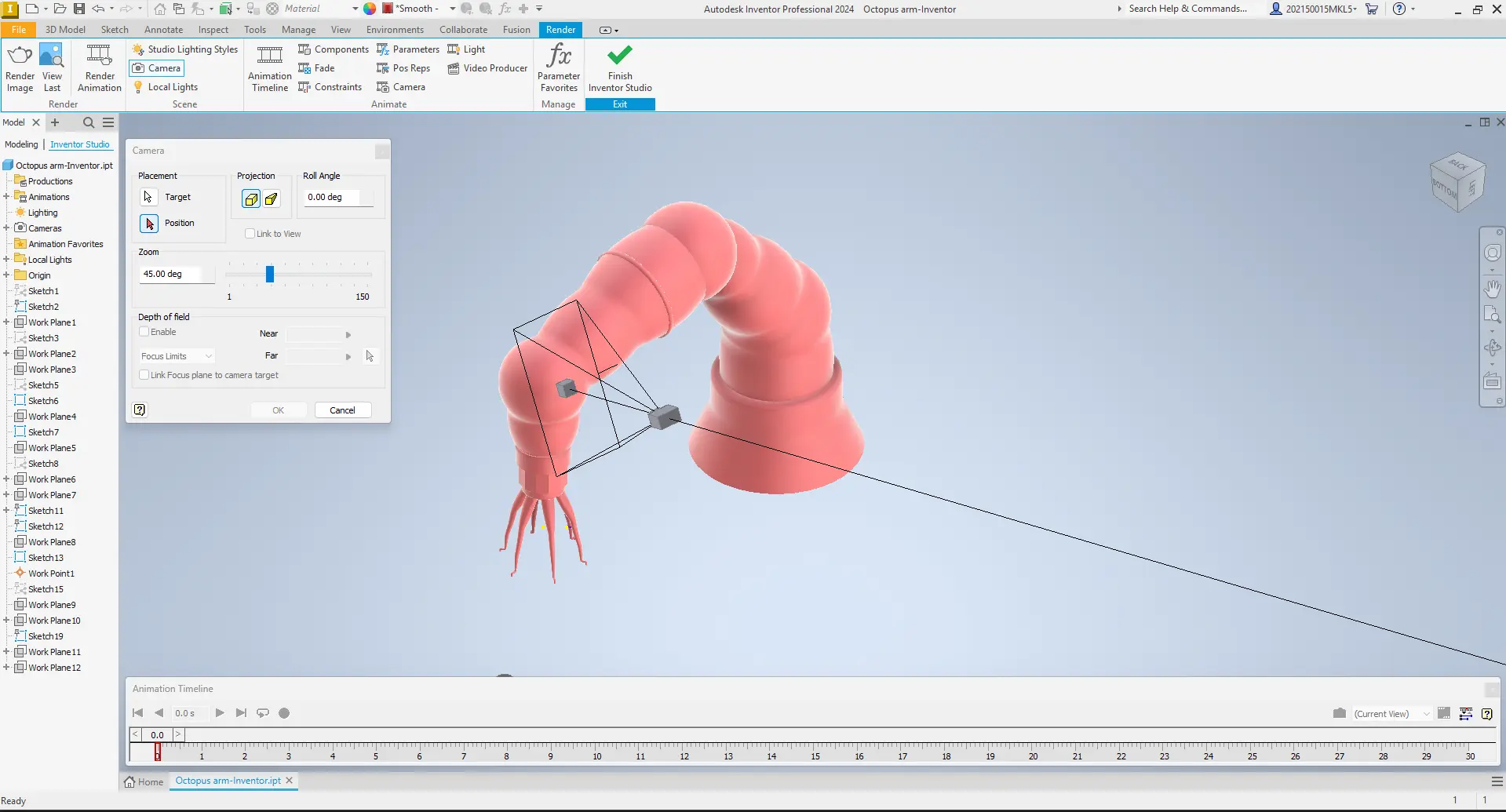
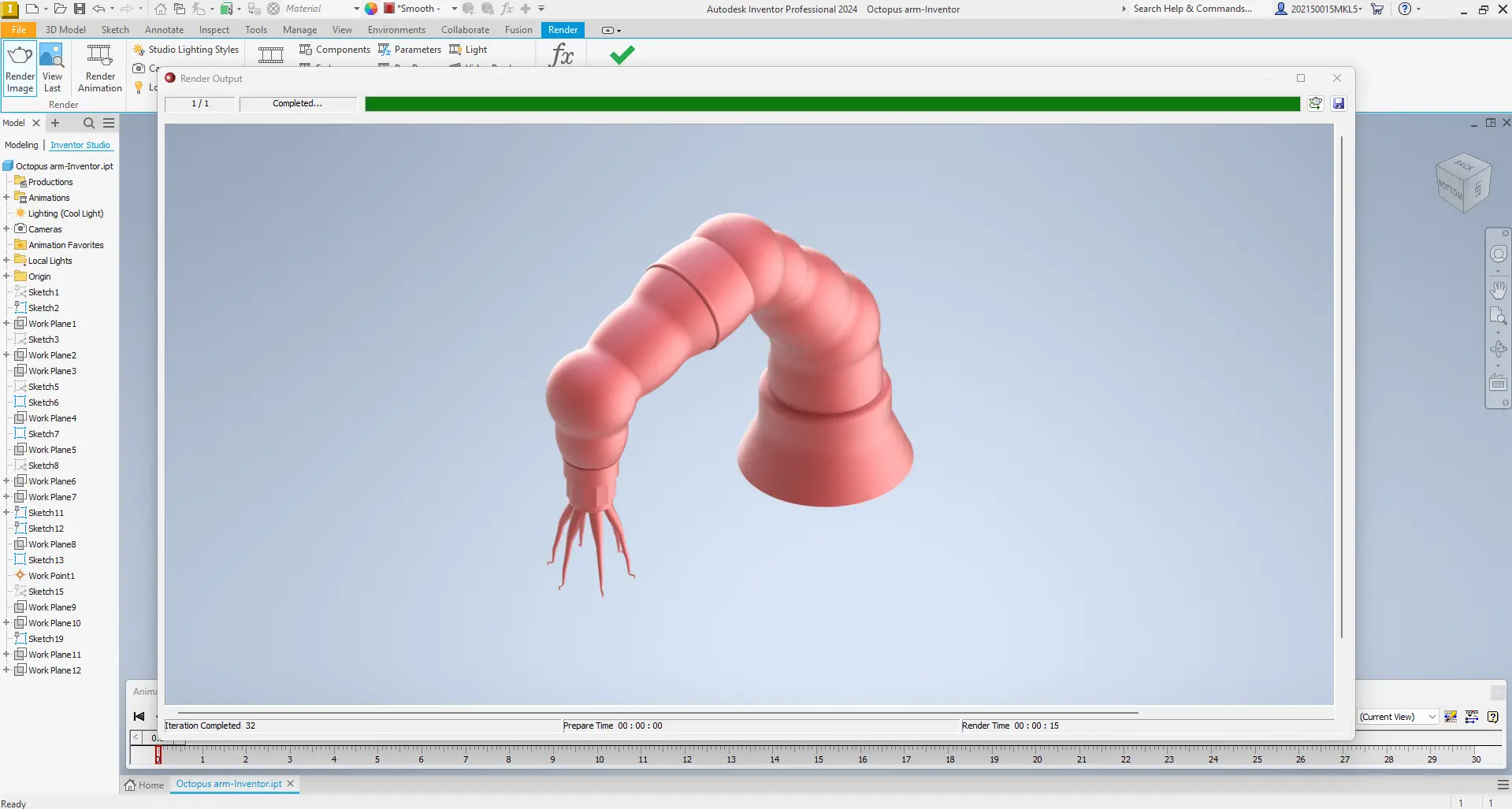
Rendering and Visualization in Autodesk Inventor
At this stage, I used Autodesk Inventor’s rendering and visualization tools to preview how my tentacle design would look in a realistic environment. I experimented with lighting, materials, and camera angles, and tested simple movements to better understand proportions and flexibility.
Fusion 360
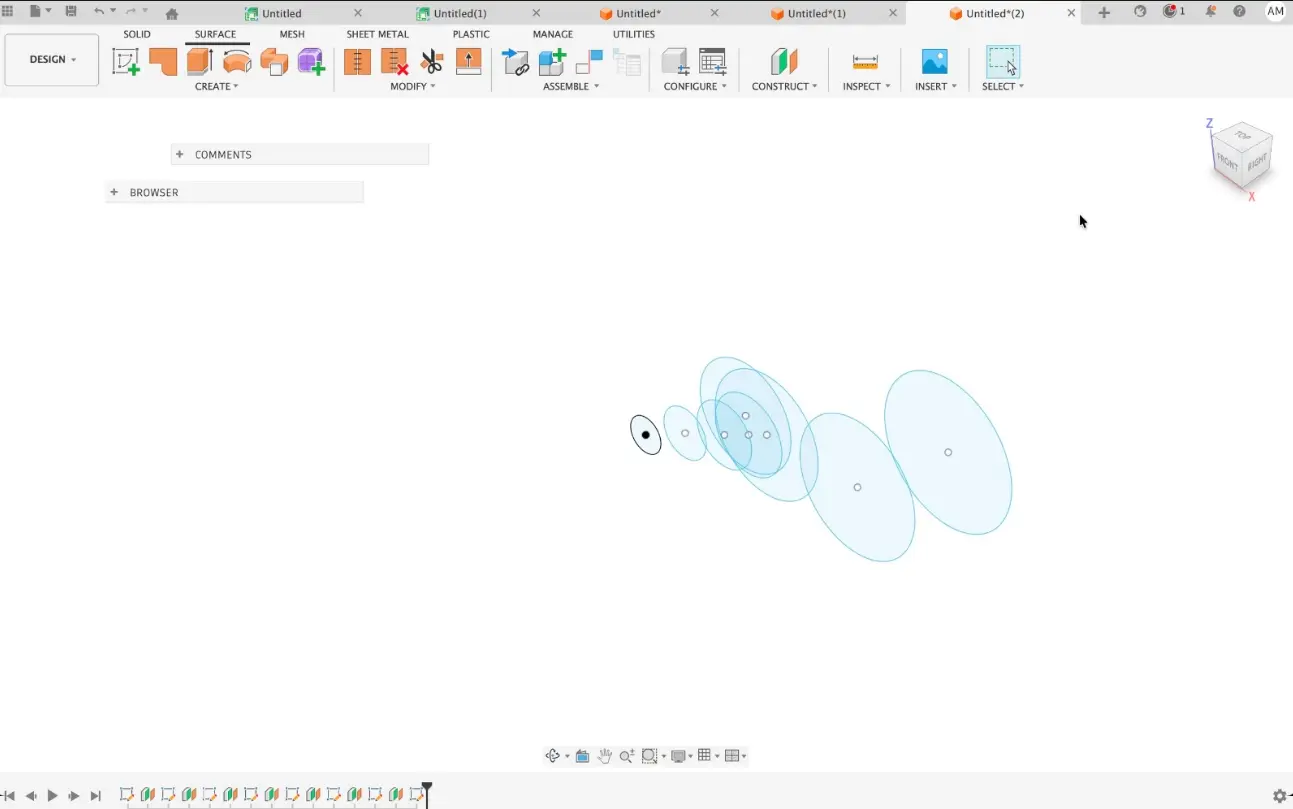
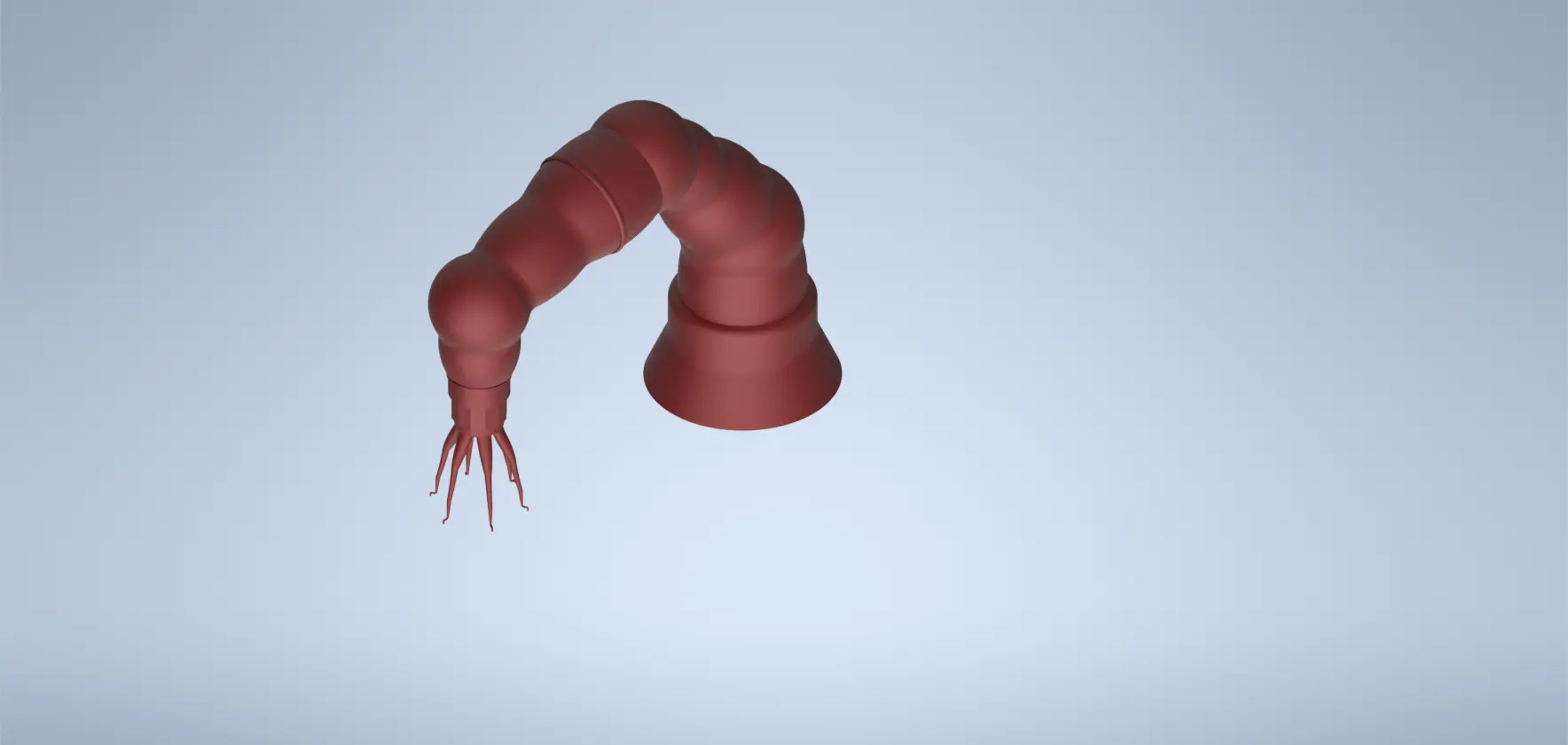
For this stage of the assignment, I had to use a different software, in this case Autodesk Fusion 360. I decided to model the tentacle by creating several sketches on different planes to achieve a smoother and more organic shape.
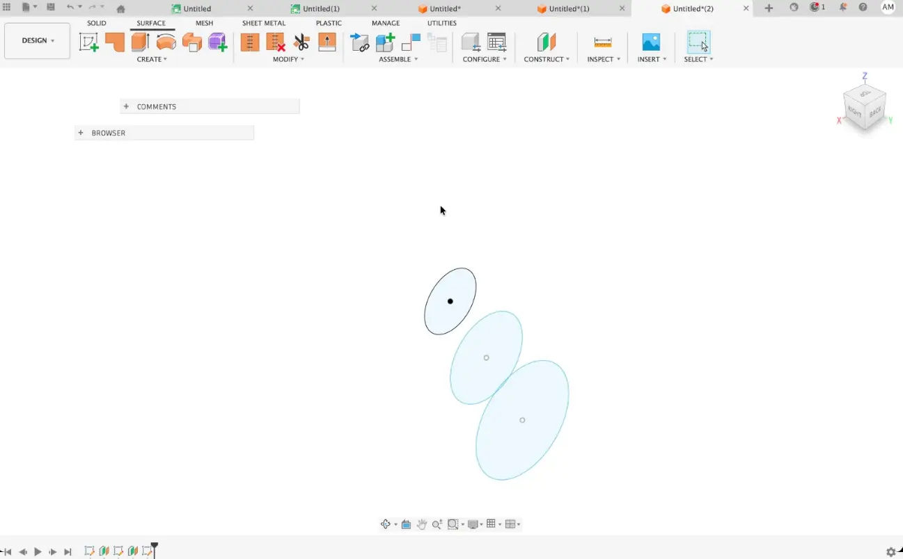
I progressively added more circular profiles, placing them plane by plane. This approach allowed me to better control the deformation of the geometry and gave the tentacle a more natural transition between sections.
After defining the profiles, I attempted to generate the geometry using the Sweep tool. However, I encountered an error because the axis I had defined intersected the circular profile at one point, which caused the sweep to fail.
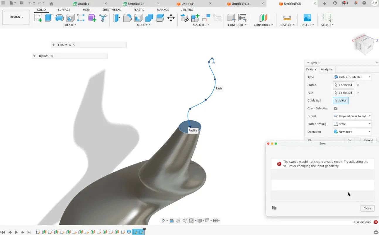
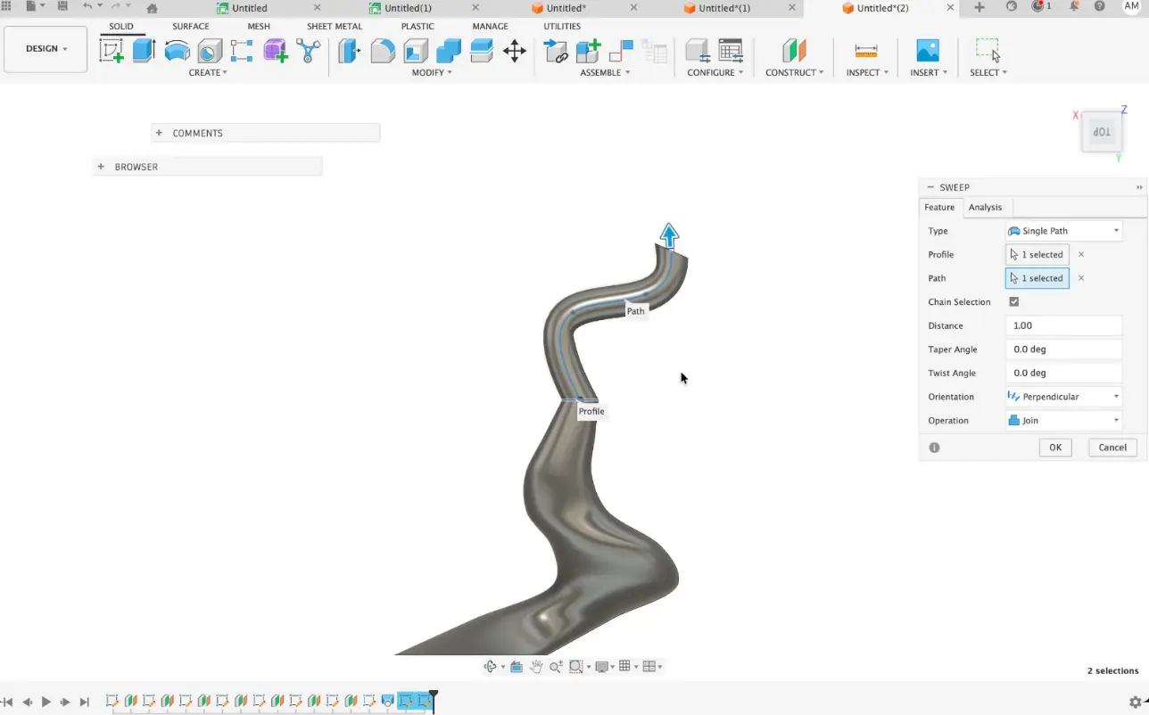
To solve this issue, I modified the reference path and adjusted the axis position so it no longer collided with the profile. Once corrected, the Sweep operation was generated successfully.
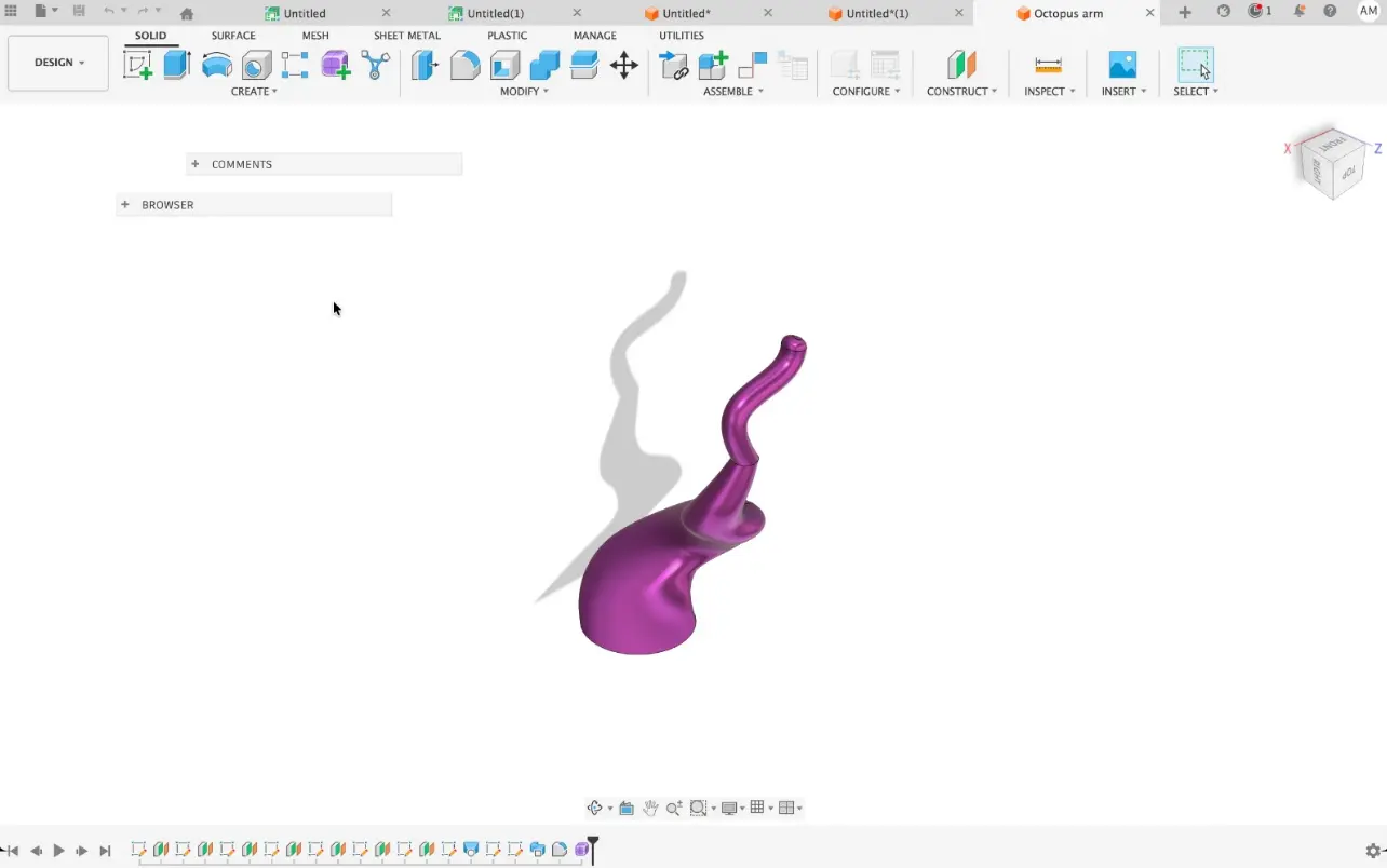
Finally, I applied a material and texture to the model to better visualize the final appearance of the tentacle. This helped me evaluate the surface continuity and overall form of the design.
3D Model (Fusion 360 Viewer)
3D Software Conclusion
During this assignment I worked with Autodesk Inventor and Fusion 360. I usually use Inventor for mechanical design, so this was one of my first experiences using Fusion 360. I found Fusion very intuitive for parametric modeling, allowing quick modifications of sketches and features while maintaining the design relationships.
Although Inventor is very powerful for complex assemblies, Fusion 360 felt more flexible and practical for rapid prototyping and digital fabrication workflows, which makes it very suitable for Fab Academy projects.
Squoosh (Image Optimization)
Squoosh is a web-based tool that I use to optimize images for my website due to its efficiency and ease of use. It reduces file size without significantly affecting visual quality.
One of the main reasons I use Squoosh is its ability to convert images to the WebP format, which reduced my images from around 3 MB to 400 KB (approximately 85% compression), improving loading times and website performance.
.webp)