What is Soft Robotics?
What got me about this was the air. Compressed air sounds like the simplest thing in the world, but push it into the right geometry and it generates enough force to grip objects of completely different shapes, sizes, and textures without crushing any of them. No motors, no gears, no torque calculations, just pressure and a well-designed cavity.
The other thing that hooked me was how these systems take direct inspiration from animals, not just aesthetically but mechanically. An octopus tentacle doesn't have bones or joints. It moves through muscle geometry and pressure distribution. This week's actuator works on exactly the same principle, three arms arranged radially, internal ribbed channels, and the whole structure curls inward when pressurized, the same way a real tentacle wraps around something.That combination, compressed air as a force source and animal anatomy as a design reference, is what makes soft robotics genuinely interesting to me.
The entire actuation system here runs on a hand pump and a 2 mm medical tube. No motors, no drivers, no code. Just air pressure and geometry. The shape of the internal ribs determines where the silicone bends, change the rib spacing and you change the motion completely.
Caucho de Silicona with catalyst is flexible enough to deform under low pressure but stiff enough to snap back to its original shape. The wall thickness (2 mm here) and the silicone stiffness together define the force-displacement curve of the whole actuator, thinner walls bend more, thicker walls require higher pressure.
Project Overview
A three-legged pneumatic soft robotic tentacle fabricated using silicone casting with a custom 3D printed mold. The actuator has three flexible arms connected to a central chamber. Inside each arm, internal ribbed air channels distribute pneumatic pressure through the structure.
When air is injected through the tube into the central chamber, the channels inflate and generate deformation in the silicone body. Due to the wall geometry and rib spacing, the structure bends and contracts, creating soft, biological-like motion.
System components
- Central air chamber, connected to the pneumatic tube for air input and distribution
- Three tentacle legs, extending from the center, designed to bend and contract
- Internal ribbed channels, distribute pressure evenly along each tentacle (10 ribs per arm, 4 mm spacing)
- Flexible silicone walls, allow controlled deformation during inflation (Shore 60A)
- Cylindrical support + cap, airtight connection for syringe or tube input
Mold Design, Autodesk Inventor
The mold was designed from scratch in Autodesk Inventor. The process goes from a simple 2D circle to a complete three-arm cavity with internal ribbed air channels, all built through extrusions, patterns, and boolean operations.
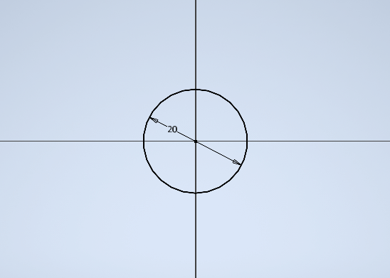
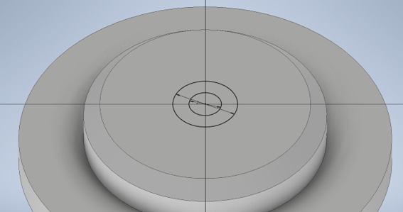
The sketch starts with a single circle of radius 20 mm centered at the origin. This circle becomes the central air distribution chamber where pressurized air enters before splitting into the three tentacle arms.
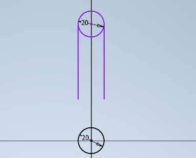
The first tentacle arm is drawn as two parallel lines extending from the central circle, capped at the end with another Ø20 mm circle. This creates the characteristic rounded-tip profile that avoids stress concentration points in the silicone during inflation.
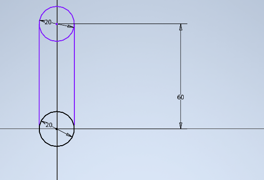
The total arm length is set to 60 mm from the center of the base circle to the center of the tip circle. This gives enough length for visible bending motion when pressurized, shorter arms would require higher pressure to produce the same deflection.
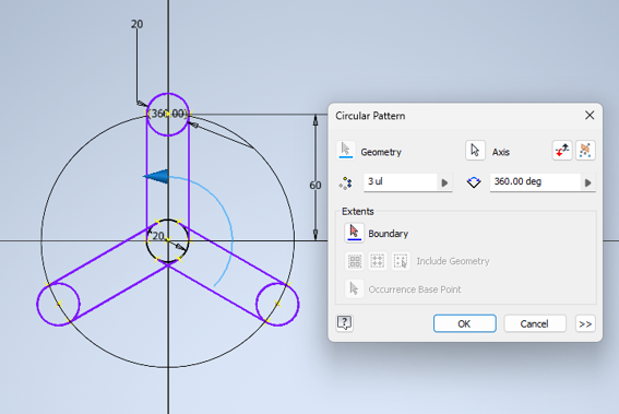
The Circular Pattern tool replicates the first arm into 3 occurrences over 360° around the center point. Each arm sits 120° apart. The result is the complete three-arm 2D profile, ready to extrude.
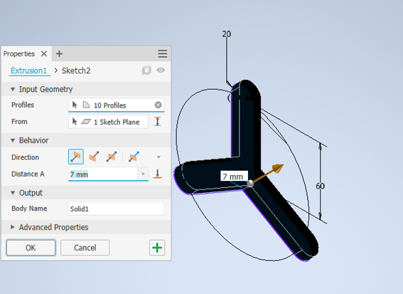
Extrusion 1 takes 10 profiles simultaneously and extrudes 7 mm to create the solid body of the mold. The 7 mm height is a balance between having enough depth for the silicone cavity and keeping the print time reasonable.
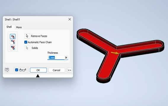
The Shell tool removes the top face and hollows the body to a 2 mm uniform wall thickness. This creates the open cavity where silicone is poured. The 2 mm wall is thin enough to allow flex in the final piece but thick enough to survive multiple casting cycles without cracking.
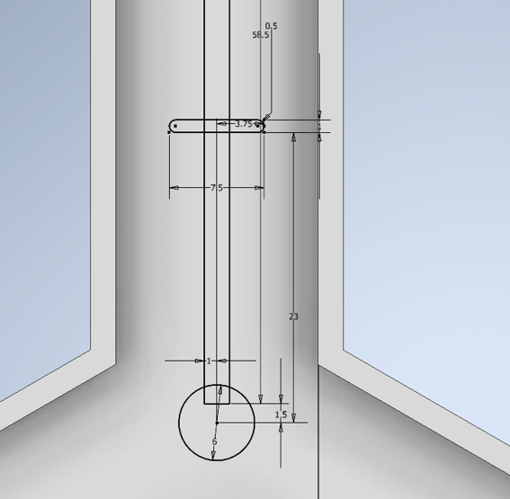
A new sketch is created inside the hollow cavity. The channel geometry: 6 mm entry circle connecting to the central chamber, ribs 7.5 mm wide × 3.75 mm tall with 1.5 mm gap between them, spanning 23 mm of the arm length. The 0.5 mm offset at the top positions the first rib at 58.5 mm from the base.
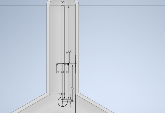
The internal sketch seen from inside the mold cavity. The rib profile and the Ø6 mm entry circle are positioned along the central axis of the tentacle arm, centered between the 2 mm walls.
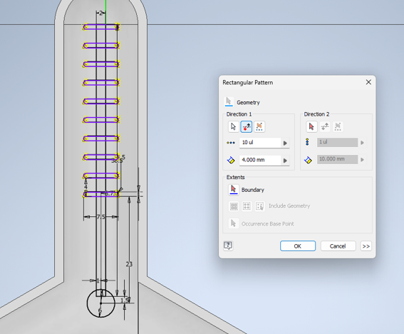
The Rectangular Pattern tool repeats the rib sketch 10 times with 4 mm spacing along the arm axis. This produces 10 evenly spaced chambers that will distribute air pressure uniformly when the silicone inflates.
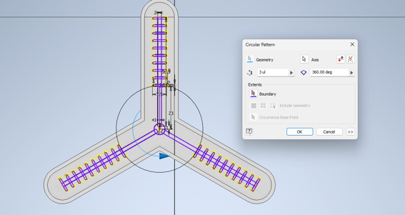
The complete ribbed channel system is replicated into the other two arms using the Circular Pattern tool again (3ul, 360°). All three tentacles now have identical internal pneumatic geometry and will inflate uniformly.
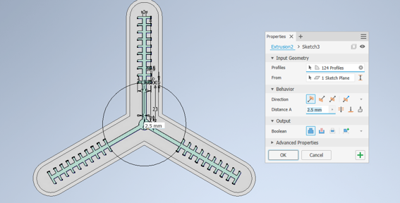
Extrusion 2 cuts all 124 rib profiles into the mold body with a 2.5 mm depth. This is a boolean cut operation, it removes material from the hollow cavity to create the physical rib geometry that will form the air chambers in the silicone.
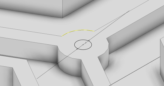
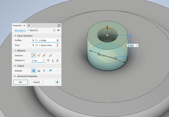
A new sketch at the center of the mold defines the Ø6 mm hole for the cylindrical support. This is where a nail is inserted during casting to create the air inlet duct, the only path connecting the external air source to the internal chamber network.
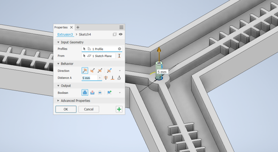
The cylindrical support post is extruded 5 mm upward from the center of the mold. This post will hold the air inlet tube in position during and after casting, creating the airtight connection between the external pump and the internal channel system.
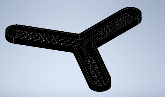
The complete mold: three-arm cavity with 10 ribs per arm (30 total), central air distribution chamber, and support post. Everything needed to cast the pneumatic actuator body in a single pour.
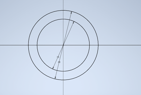
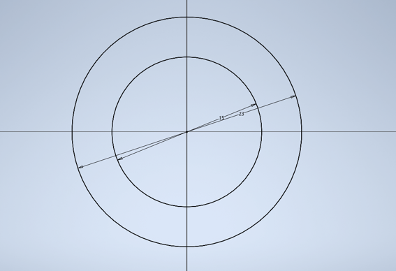
The cap sketch starts with two concentric circles centered at the origin: inner radius 15 mm and outer radius 23 mm. This annular profile defines the wall cross-section of the cylindrical cap that will press-fit onto the support post.
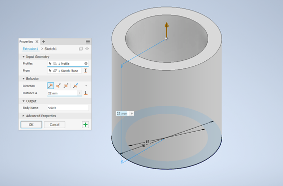
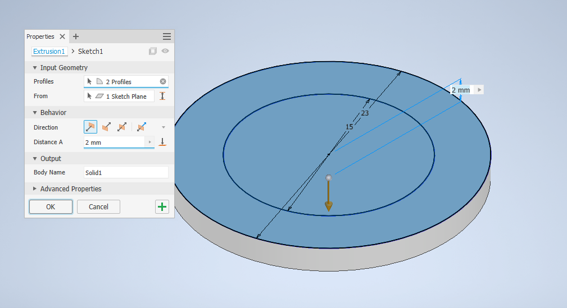
Both annular profiles are extruded 2 mm downward to create the base flange of the cap. This flat ring is the seating surface that contacts the top of the silicone actuator when the cap is installed.
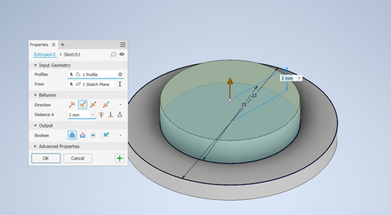
The outer annular profile (Ø23 mm) is extruded upward 3 mm to form the outer wall of the cap cylinder. The inner profile is left open at this stage, creating the hollow bore through which the air tube passes.
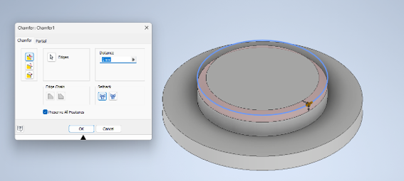
A 1 mm chamfer is applied to the upper outer edge of the cylinder. This bevel removes the sharp corner that would otherwise concentrate stress during insertion, and makes the cap easier to handle and install onto the support post.
A new sketch is created on the top face of the base flange, placing the inner circle geometry for the hollow center column. This sketch drives the next extrusion that forms the tube connection bore.
The inner annular profile is extruded upward 3 mm to form the hollow center column. This creates the concentric cylinder that slides over the support post of the mold, forming the airtight press-fit connection for the pneumatic tube.
A 1 mm boolean cut is made at the top of the inner column to create the seating rebate. This recessed lip locks the air tube in place and prevents it from slipping out under positive pressure during operation.
The finished cap: base flange (2 mm), outer cylinder with chamfered edge (3 mm), and inner hollow column with seating rebate (3 mm body + 1 mm cut). The cap slides over the mold support post and receives the pump tube, forming the only air path into the actuator's internal channel system.
Silicone Casting
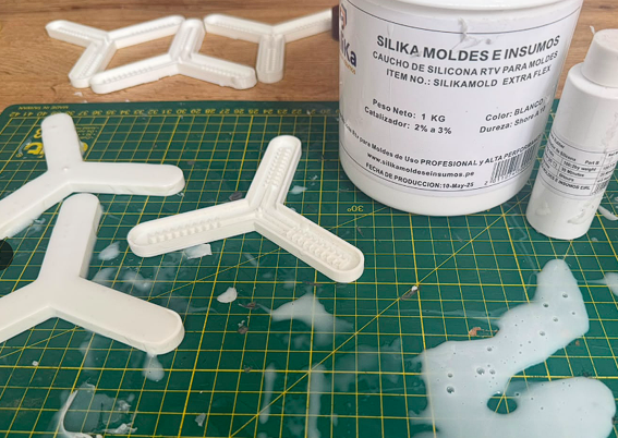
Material used: Silika Moldes e Insumos, Caucho de Silicona RTV SILIKAMOLD EXTRA FLEX, Shore A 10, with its catalyst at 2–3% by weight. This is a professional-grade flexible silicone designed for high-performance molds, the Shore A 10 rating means it deforms easily under low pressure, which is exactly what a pneumatic actuator needs. Catalyst ratio is critical: too little and the silicone stays tacky; too much and it gels before the pour is done.
Casting parameters
Process
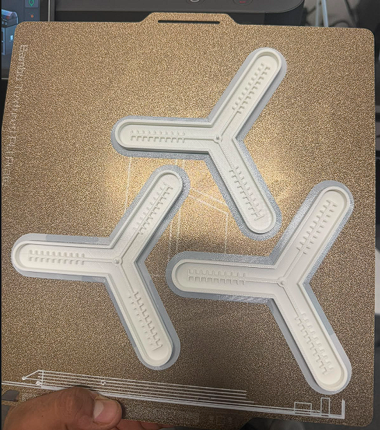
Three tentacle molds printed in PLA directly from the Autodesk Inventor design. The ribbed internal cavity detail is visible on the surface of each arm. Printing three at once ensured a backup in case one failed during demolding and gave material for the two-pour process.
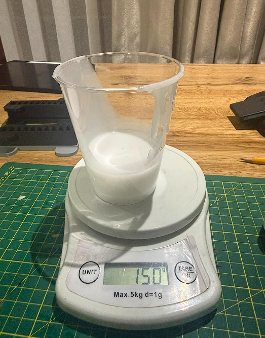
Measured 150 g of Silika EXTRA FLEX silicone base into a plastic mixing cup on a digital scale (tared). The white, paste-like consistency is typical before the catalyst is added. This amount was calculated to fill both the mold cavity and leave enough for the flexible sealing layer.
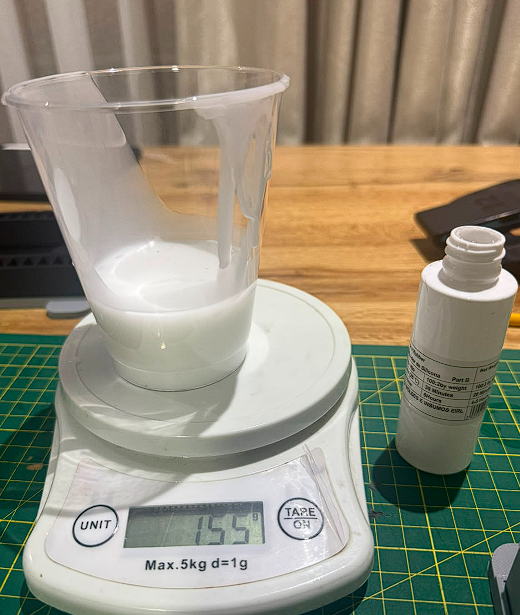
Catalyst (Part B) was added dropwise until the scale read 155 g, approximately 5 g of catalyst into 150 g of silicone, landing at 3.3% within the 2–3% specification window. The bottle label confirms compatibility: same Silika Moldes e Insumos supplier, 100:2 ratio by weight. Mixed thoroughly for 2–3 minutes scraping the cup walls to avoid unmixed pockets.
Poured the mixed silicone into the molds, working quickly within the 30-minute open time. The ribbed internal cavity requires careful filling, the mix was poured slowly along one wall to let it flow into the rib pockets without trapping air. After pouring, tapped each mold firmly on the table surface to drive bubbles upward. Silika EXTRA FLEX Shore A 10 is the softest formulation available at Fab Lab ULima, chosen specifically so the channels inflate at the lowest possible hand-pump pressure.
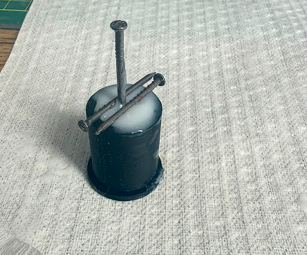
The cylindrical PLA support cap with two nails inserted through the bore. The nails create the hollow air tunnel: once the silicone cures and they are removed, the resulting channel is the only path connecting the external pump to the internal rib network. Two nails were tested to verify the alignment, only one is used in the final assembly. The cap was pressed onto the tentacle mold center post before the silicone set.
After 5 hours at room temperature, both tentacle bodies were released from their PLA molds. The silicone peels cleanly away from PLA without a mold release agent, a key advantage of RTV silicone. The smooth top surface is the face that will later bond to the flexible sealing layer. No tearing or warping in either piece.
Video, Demolding the octopus mold
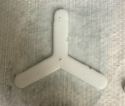
The internal channel side of the cured tentacle, this is the face that sits face-down when the flexible sealing layer is applied. Small surface bubbles are visible near the tip of one arm; these are cosmetic and don't affect the structural integrity or pneumatic performance since they don't penetrate the wall thickness.
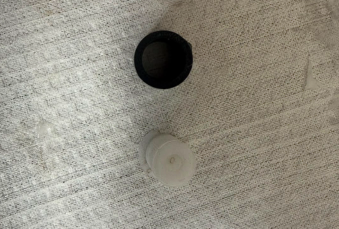
Two versions of the cap: the original black PLA 3D printed cap (top) and a silicone-cast white cap (bottom). The silicone cap was cast as an alternative to test whether a fully flexible interface would improve the airtight seal at the tube connection point. The PLA cap creates a rigid-to-flexible junction; the silicone cap creates a flexible-to-flexible bond with the tentacle body.
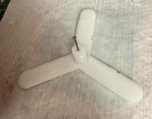
The cured tentacle body with the nail still inserted in the central support post, before it was pulled out to open the air duct. This view shows the correct geometry: the support post rises cleanly from the center junction, the three arms are level, and the overall shape matches the CAD design. Pulling the nail out straight (not at an angle) is important to avoid tearing the duct wall.
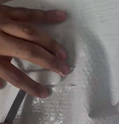
Fresh silicone is spread onto a sheet of paper/cloth as the base layer, then the tentacle body is pressed down channel-side first onto the wet silicone. The hand pressure ensures full contact between the tentacle's open channel faces and the new layer, bonding them together to seal all internal air chambers. The paper acts as a backing that peels away after the second cure, leaving only the silicone layer bonded to the tentacle.
Video, Applying the flexible sealing layer
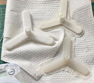
The two completed tentacle actuators after the second 5-hour cure. The flexible sealing layer has bonded fully to the channel faces, closing all internal air chambers. The central support post with its bore hole is visible on the upper piece. Both actuators are structurally identical and ready for pneumatic testing. The excess silicone flash around the perimeter was trimmed with a precision knife before final assembly.
Testing and Results
Air was supplied via a balloon pump and 2 mm diameter medical tube. When pressurized, the three tentacle arms curled inward in a coordinated hand-like configuration.