Assignments
Assignment
Individual assignment
- Define and apply system integration to your final project
Project Overview – Octopus Gripper
A soft robotic gripper inspired by octopus tentacles, designed as a modular end-effector for the UR3 robotic arm. The operator controls the gripper intuitively by bending their fingers while wearing a glove equipped with flex sensors. Bending a finger causes the corresponding tentacle to replicate the motion in real time via Bluetooth Low Energy, no cables between glove and gripper.
Each tentacle is printed in TPU 95A with 12 segmented vertebrae and a Dyneema tendon through the central channel. The servo pulls the tendon bending the tentacle up to 120°. Two independent microcontrollers: an XIAO ESP32-C6 on the glove (TX) and an XIAO ESP32-C6 on the gripper (RX). Both communicate exclusively via BLE.
TPU Tentacles
12 segmented vertebrae per tentacle. Dyneema tendon through central channel pulled by SG90 servo — bends up to 120°.
Flex Sensor Glove
3 flex sensors (10–40 kΩ) sewn onto the glove. Voltage divider → ESP32 12-bit ADC → 4096 resolution steps at 20 Hz.
BLE — 2 independent boards
XIAO ESP32-C6 (TX/glove) packs "A1,A2,A3". XIAO ESP32-C6 (RX/gripper) parses and drives the 3 servos. No physical cables.
UR3 Integration
3D-printed ISO 9283 adapter fixes the gripper to the UR3 flange. The arm positions in 3D; BLE handles grasping autonomously.
System Integration Diagram
The diagram below shows how every subsystem merges and interacts — from the flex sensors on the glove, through the BLE wireless link, to the servo-driven tentacles mounted on the UR3 arm.
System Diagrams
The project is divided into two independent systems that communicate wirelessly via BLE.
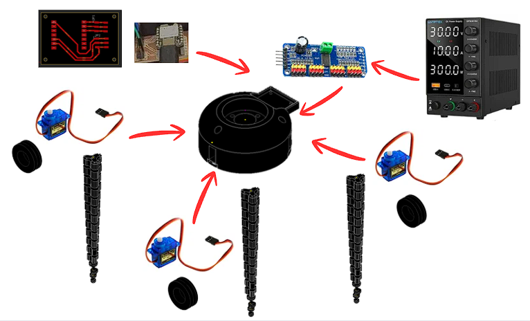
Gripper System
Glove System
Gripper — Components
- Custom PCB — XIAO ESP32-C6 (BLE RX)
- PCA9685 — 16-ch PWM servo driver (I2C)
- SG90 x3 — micro servo per tentacle
- TPU 95A tentacle x3 — 12 vertebrae + Dyneema
- Hub — 3D-printed servo mount + cable routing
- DC power supply — bench supply for development
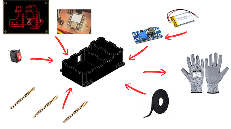
Glove — Components
- Custom PCB — XIAO ESP32-C6 (BLE TX)
- Flex sensors x3 — sewn onto glove fingers
- MT3608 boost converter — 3.7V to 5V step-up
- LiPo 3.7V 1000mAh — battery
- Rocker switch — power on/off
- 3D-printed enclosure — houses PCB + battery
- Velcro tape — attaches enclosure to glove
- Work glove — base for sensor mounting
Signal path — full system
How every subsystem connects, from flex sensors on the glove through BLE to the servo-driven tentacles on the UR3.
Voltage divider
0-3.3 V output
map 0-4095 → 0-120°
BLE GATT TX
JP1-JP3 connectors
LiPo battery
Packet: "A1,A2,A3"
50 ms interval · ~10 m
No cables glove to gripper
Parse "A1,A2,A3"
Gripper PCB board
500-2500 us range
0-120° rotation
Dyneema tendon
Bends to 120°
Custom 3D-printed adapter
Bayonet flange mount
Positions in 3D · gripper operates independently via BLE
UR3 Robotic Arm – Integration
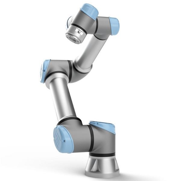
The Universal Robots UR3 is a 6-axis cobot with 3 kg payload and 500 mm reach. The arm handles 3D positioning while the BLE system independently manages gripper opening and closing.
- Payload: 3 kg · Reach: 500 mm
- Axes: 6 DOF
- Gripper mount: 3D-printed ISO 9283 adapter
- Gripper control: Wireless BLE, independent from arm controller
Tentacle CAD Design – Autodesk Inventor + TPU
The tentacle was modeled in Autodesk Inventor with 12 identical vertebrae linked by flexible hinges. After 12 print iterations the optimal parameters were found. The tapered profile replicates real cephalopod arm geometry and distributes stress evenly along the full length.
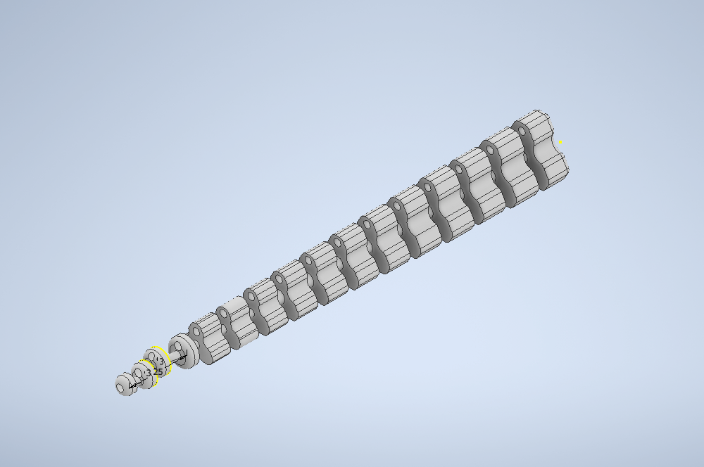
CAD design in Autodesk Inventor — TPU 95A tentacle, 12 vertebrae, central Dyneema channel.
Final print parameters – TPU 95A
Flex Sensor Glove – Electronics
How does the flex sensor work?
Flex sensors are variable resistors: at rest they measure ~10 kΩ and increase up to ~40 kΩ when bent. They are wired in a voltage divider with 10 kΩ to GND. The output reaches the XIAO ESP32-C6 ADC with 12-bit resolution (0–4095). The firmware maps each ADC value to the 0°–120° range and packs it as "A1,A2,A3" for BLE.
- Range: 10 kΩ (flat) → 40 kΩ (bent 90°)
- Supply: 3.3 V from XIAO ESP32-C6
- Pull-down: 10 kΩ voltage divider
- ADC Resolution: 12 bits = 4096 steps/channel
- Sampling: 20 Hz — 50 ms cycle
- Pins: A0, A1, A2 on XIAO ESP32-C6
My PCBs – Glove & Gripper Boards
Two custom boards designed in Fusion 360 Electronics and milled on a Roland MDX-50. Each hosts a microcontroller and communicates via BLE, no shared wiring between glove and gripper.
SMD Assembly with solder paste
SMD resistive components are soldered using solder paste. Process: apply paste through stencil, place components with tweezers, cure with heat gun. Ensures more reliable and compact connections than hand soldering.
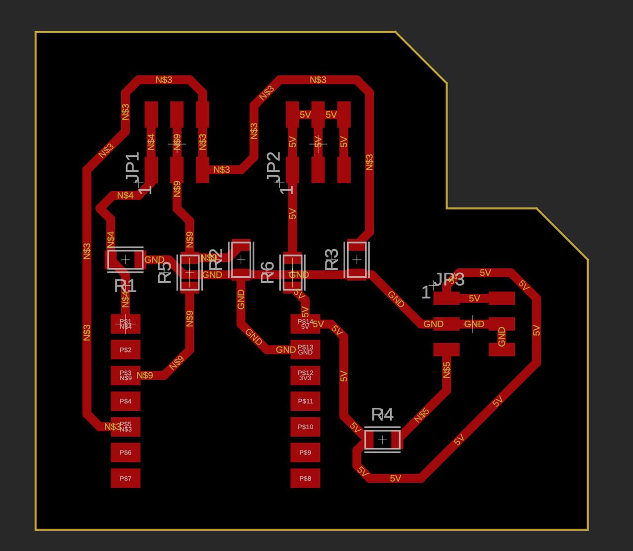
Glove PCB – TX (XIAO ESP32-C6)
JP1, JP2, JP3 connectors for the three flex sensors. Six SMD resistors form the voltage dividers. Runs BLE GATT TX firmware.
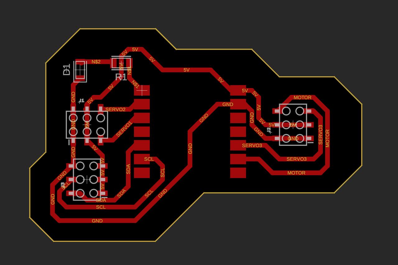
Gripper PCB – RX (XIAO ESP32-C6)
Three servo headers (Signal/5V/GND). BLE status LED. XIAO ESP32-C6 with high-efficiency BLE 5.0.
Interactive System Nodes
Click each node to see detailed information about that subsystem.
3× Flex Sensors · Voltage divider
XIAO ESP32-C6
XIAO ESP32-C6
ISO 9283 Adapter
3 axes · Dyneema Tendon
3× SG90 · PWM 50 Hz
1. Wearable Glove – Flex Sensors
Three flex sensors sewn onto the glove fingers. Each sensor changes resistance from 10 kΩ (flat) to 40 kΩ (bent). A voltage divider converts to 0–3.3 V, read by the ESP32 12-bit ADC at 4096 resolution steps and 20 Hz sampling rate.
BLE Packet Visualizer
Every 50 milliseconds, the glove reads the three flex sensors and packs the angles into a single text string, for example "30,60,90". Move the sliders to simulate bending your fingers.
A1: --°
A2: --°
T2: --°
T3: --°
Firmware – BLE Transmitter (Glove)
// BLE Transmitter — Wearable Glove
// XIAO ESP32-C6 | Fab Academy W15
#include <BLEDevice.h>
#define SERVICE_UUID "4fafc201-1fb5-459e-8fcc-c5c9c331914b"
#define CHAR_UUID    "beb5483e-36e1-4688-b7f5-ea07361b26a8"
#define FLEX1 A0
#define FLEX2 A1
#define FLEX3 A2
BLECharacteristic *pChar;

void setup() {
  BLEDevice::init("OctopusGlove");
  BLEServer *srv = BLEDevice::createServer();
  BLEService *svc = srv->createService(SERVICE_UUID);
  pChar = svc->createCharacteristic(
    CHAR_UUID, BLECharacteristic::PROPERTY_NOTIFY);
  svc->start(); BLEDevice::startAdvertising();
}

void loop() {
  int a1 = map(analogRead(FLEX1), 0, 4095, 0, 120);
  int a2 = map(analogRead(FLEX2), 0, 4095, 0, 120);
  int a3 = map(analogRead(FLEX3), 0, 4095, 0, 120);
  String pkt = String(a1)+","+String(a2)+","+String(a3);
  pChar->setValue(pkt.c_str()); pChar->notify();
  delay(50);
}
Firmware – BLE Receiver (Gripper)
// BLE Receiver — Gripper Controller
// XIAO ESP32-C6 | Fab Academy W15
#include <BLEDevice.h>
#include <ESP32Servo.h>
Servo s1, s2, s3;
int angles[3] = {0,0,0};

class CB: public BLECharacteristicCallbacks {
  void onWrite(BLECharacteristic *p) {
    String v = p->getValue().c_str();
    int i1=v.indexOf(','), i2=v.indexOf(',',i1+1);
    angles[0]=v.substring(0,i1).toInt();
    angles[1]=v.substring(i1+1,i2).toInt();
    angles[2]=v.substring(i2+1).toInt();
  }
};

void setup() {
  s1.attach(3); s2.attach(4); s3.attach(5);
  BLEDevice::init("");
}

void loop() {
  s1.write(angles[0]);
  s2.write(angles[1]);
  s3.write(angles[2]);
  delay(20);
}
Communication Protocols
| Protocol | Speed | Range | Cables | Use |
|---|---|---|---|---|
| I2C | 400 kHz | On Board | 2 | Sensor bus |
| UART | 115200 baud | Short cable | 2 | Debug / serial |
| SPI | 8 MHz | On board | 4 | Display / peripherals |
| BLE ✓ | 1 Mbps | ~10 m | 0 | Gripper |
Why BLE and not WiFi, UART or I2C?
The XIAO ESP32-C6 in BLE mode consumes ~3 mA, ideal for battery-powered operation on the gripper.
Eliminates tangled cable issues during UR3 arm movement.
BLE GATT notifications deliver angles at 50 ms per cycle, sufficient for smooth servo control.
The gripper operates as an independent module — no need to connect to the UR3 controller.
Packaging and Finished Product
The Octopus Gripper is designed as a self-contained, modular end-effector. Every component fits within a compact form factor that mounts directly to the UR3 flange and operates independently over BLE.
Gripper Assembly
Three TPU 95A tentacles radially distributed around a central PLA hub. Gripper PCB (XIAO ESP32-C6) sits inside the hub cavity. Total diameter: ~120 mm. All tendons and servo cables routed internally — no exposed wiring.
Wearable Glove
Three flex sensors sewn onto a neoprene glove. Glove PCB (XIAO ESP32-C6) attaches to the back of the hand via velcro strap. LiPo battery tucked under the PCB. Fully wearable and wireless — no cables to the gripper.
UR3 Adapter
ISO 9283-compliant adapter printed in PLA, bolts directly to the UR3 tool flange with M4 screws. Gripper locks into adapter via quarter-turn bayonet for fast swap without tools.
Cable management
All Dyneema tendons are routed through printed channels internal to the hub structure. Servo cables are short and tucked inside the same housing, giving the gripper a clean finished appearance with no loose wires on the outer surface.
Project Timeline – Gantt
| Task | Week 1 | Week 2 | Week 3 | Week 4 | Week 5 | Week 6 |
|---|---|---|---|---|---|---|
| CAD Autodesk Inventor | ||||||
| TPU Printing | ||||||
| PCB + Milling | ||||||
| SMD Solder paste | ||||||
| Firmware BLE TX/RX | ||||||
| UR3 Integration | ||||||
| Testing & Demo | ✓ Demo |
Link to Final Project
The system integration documented in this week is part of the complete Octopus Gripper final project. Full documentation including CAD files, firmware, assembly guide, bill of materials, and video demonstration is on the final project page.