Assignments
Assignment
Group assignment
- Review the safety data sheets for each of your molding and casting materials, then make and compare test casts with each of them.
- Compare mold making processes (printing vs milling).
Individual assignment
- Design a mold around the process you'll be using, produce it with a smooth surface finish that does not show the production toolpath, and use it to cast parts.
Group Assignment
Safety Data Sheet Highlights
Before working with any molding or casting material, it is essential to review the Safety Data Sheet (SDS) for each product. Use the tabs below to explore the material properties, required equipment, and a visual comparison of each material.
Test Casts — Material Comparison
We made test casts with each available material to compare their behavior, surface quality, and ease of use. The brain figure was used as the test master for consistency across all materials.
Silicone Rubber — with catalyst
Mixed at 78g silicone + 2g catalyst. Very flexible result, good detail capture. Cure time 6–8 hours. Not food safe.
F20 Plus — two-part, no catalyst
Mixed 1:1 by weight. Slightly firmer, very good surface detail. Cure time 4–6 hours. Food safe.
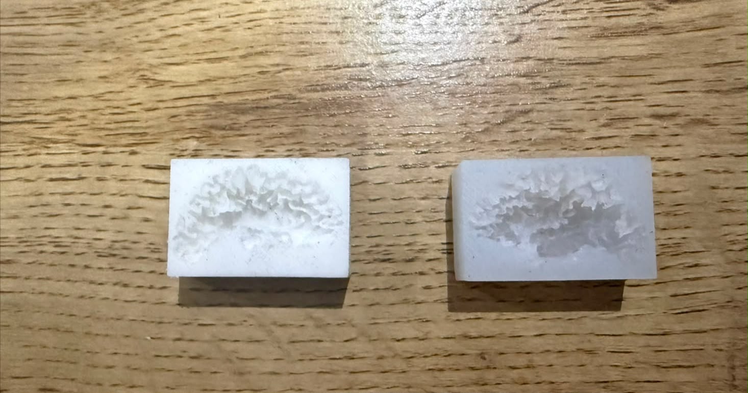
Both test casts side by side:
Material Comparison
| Property | Silicone Rubber | F20 Plus |
|---|---|---|
| Mix type | Base + catalyst | Two-part (A+B) |
| Ratio | 78g silicone + 2g catalyst | 1:1 by weight |
| Food safe | No | Yes |
| Flexibility | Very flexible | Slightly firmer |
| Surface detail | Good | Very good |
| Cure time | 6 to 8 hours | 4 to 6 hours |
| Ease of demolding | Good | Very good |
For more detail on the Group Assignment, visit the official Fab Academy page:
Visit Fab Academy ULima →Individual Assignment
For this assignment I designed a small dog figure and machined the mold out of a blue wax block using the Roland MDX-540. Then I made silicone molds from that master and cast the final piece in chocolate and resin. Below I'm documenting each step of the process.
3D Design in Autodesk Inventor
I designed the figure in Autodesk Inventor. I started from a reference image, created a sketch following the outline, extruded it with a slight taper angle so the silicone would release cleanly later, and added details with fillet and chamfer tools. The taper angle is important — if the walls are perfectly vertical, the silicone grips the inside and it's hard to pull out without tearing. Around 8 to 10 degrees works well.
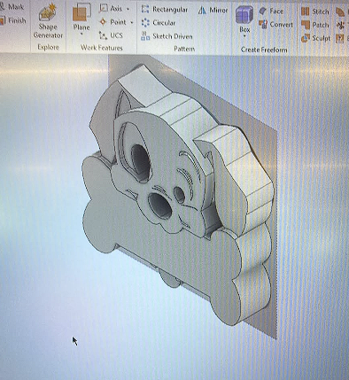
Dog figure in Autodesk Inventor
The dog figure modeled in Autodesk Inventor with draft angles applied to all vertical walls. The stepped sides show the taper that allows the silicone to release cleanly after curing. All details — eyes, nose, ears, bone — were built using extrude and fillet operations on a base sketch.
Materials
I used three different silicones. Click each one to compare their properties, mix ratios, and how I used them.
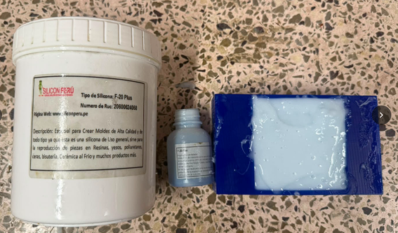
F-20 Plus Silicone — Silicon Perú
The F-20 Plus from Silicon Perú comes as a base (large white jar) and a small catalyst bottle. General-purpose silicone for high-quality mold making. The blue block is the freshly 3D-printed mold case ready to receive the wax master.
3D-Printed Mold Case
Before machining the wax block I designed and 3D printed a containment case to hold the block while the silicone is poured. The case has walls tall enough to cover the figure completely plus a few extra millimetres of silicone above it.
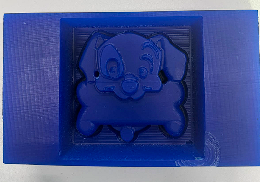
3D-printed blue case — top view
The blue PLA case printed on a FDM printer. The dog figure sits raised inside the cavity as a positive master. The rectangular outer walls form the containment box that will be filled with silicone.
Machining the Mold — Roland MDX-540
With the STL file ready I used SRP Player to set up the toolpaths for the Roland MDX-540. The material is a blue wax block. The process has two passes: roughing to remove most of the material fast, and finishing to get a smooth surface.
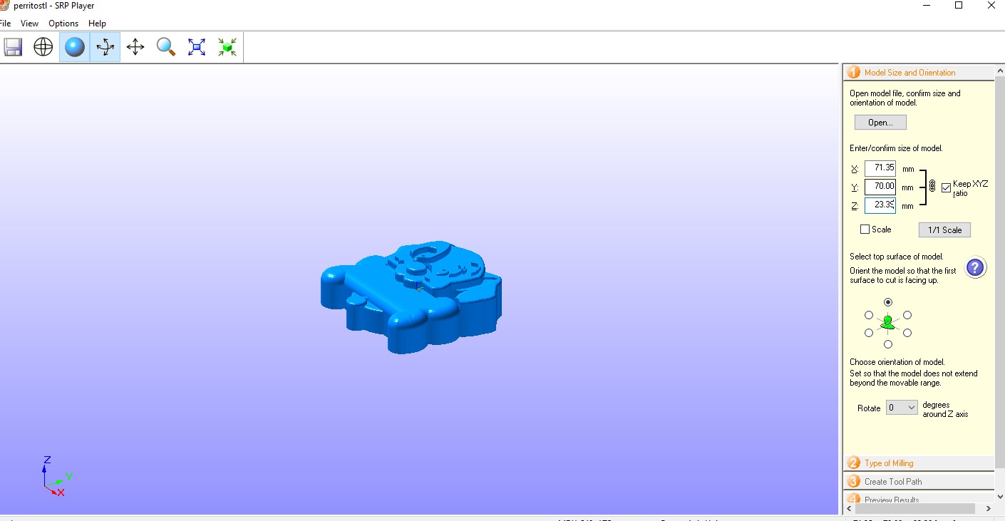
Model size — small version
71.35 × 70.00 × 23.35 mm. XYZ ratio locked, top surface set as the face to cut.
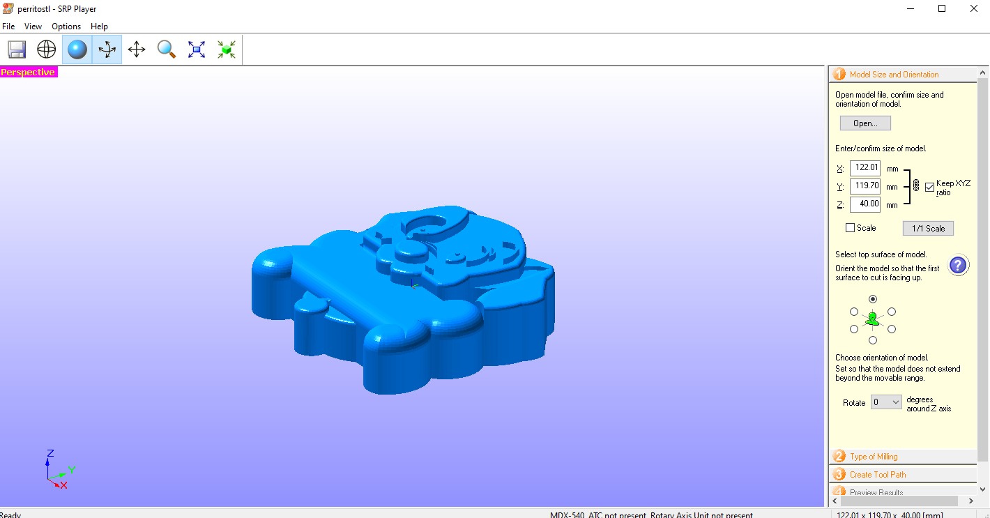
Model size — large version
122.01 × 119.70 × 40.00 mm. The final mold used the large block dimensions.
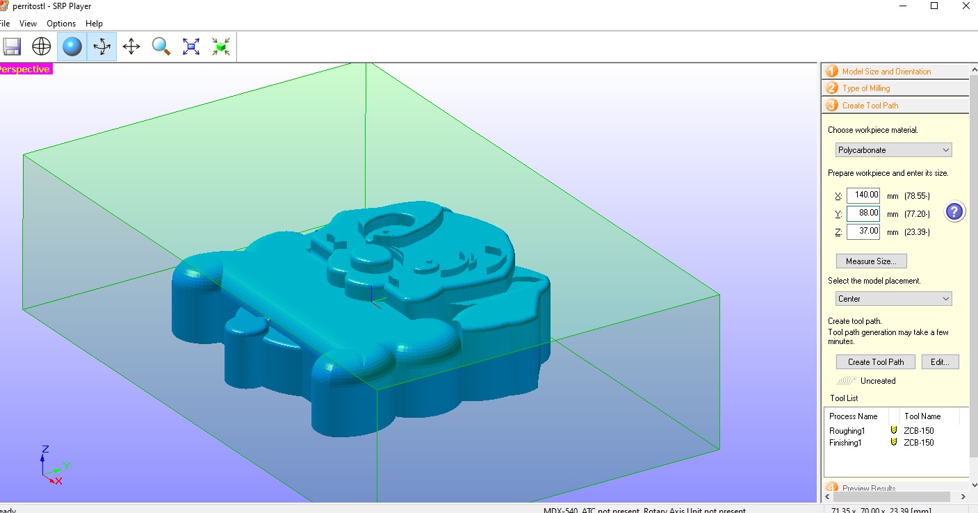
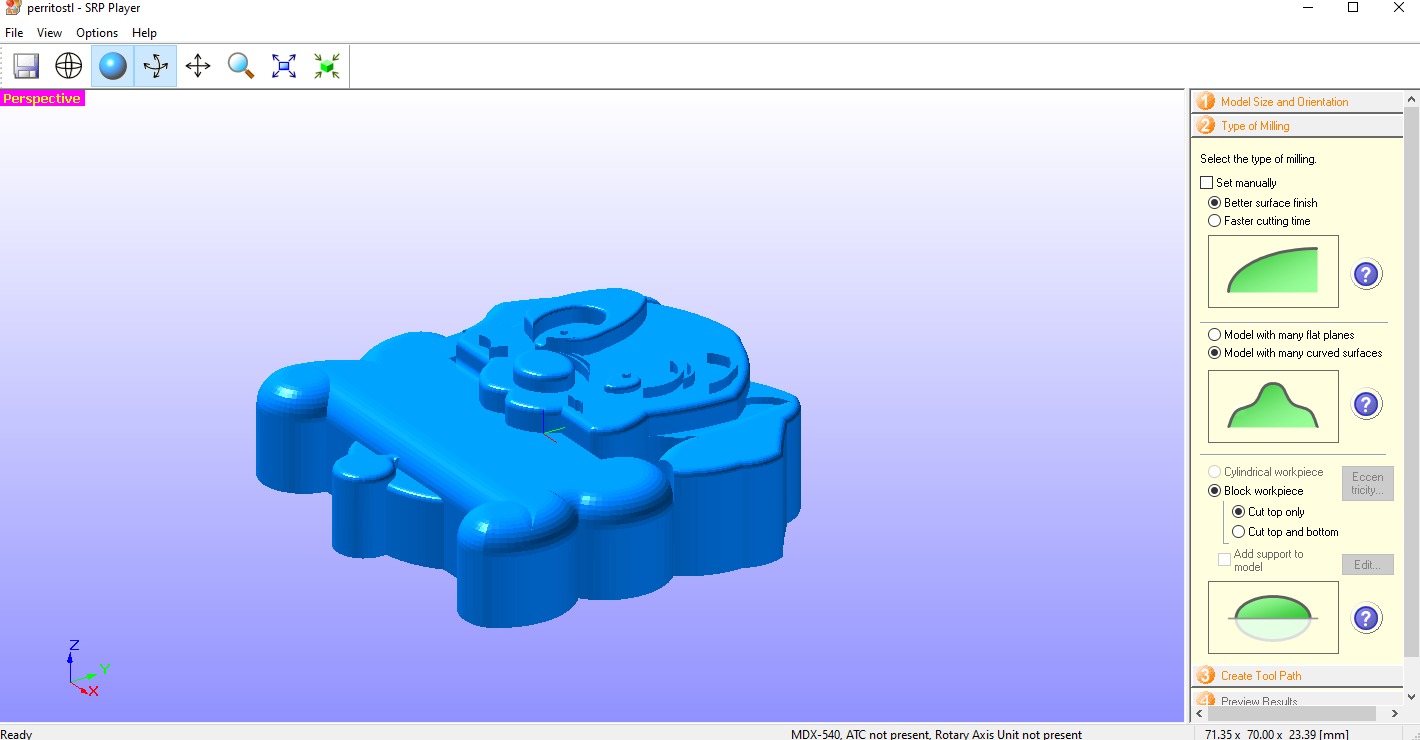
Type of milling
I chose "Better surface finish" and "Model with many curved surfaces". Cut top only — single-sided open mold.
Workpiece setup
Block dimensions: 140 × 88 × 37 mm. Material: Polycarbonate. Model placement: Center.
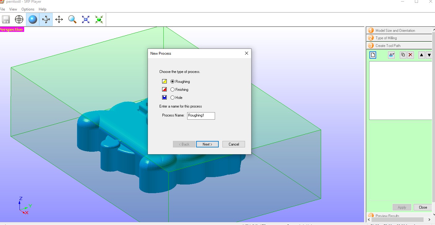
Creating the roughing process
Clicked "New Process" and selected Roughing to generate the first toolpath for material removal.
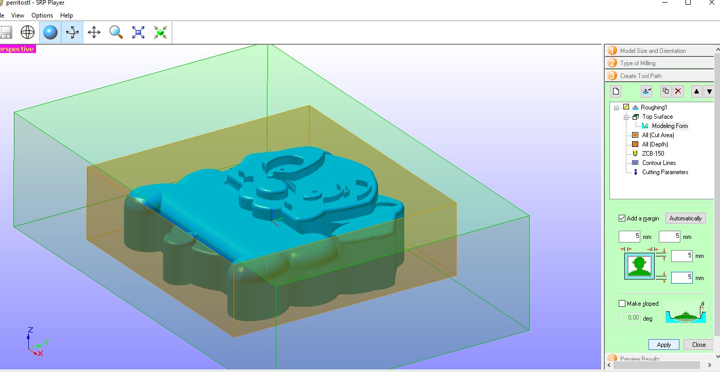
Roughing area and margins
5 mm margin on all sides. "Make sloped" unchecked — taper applied in finishing pass.

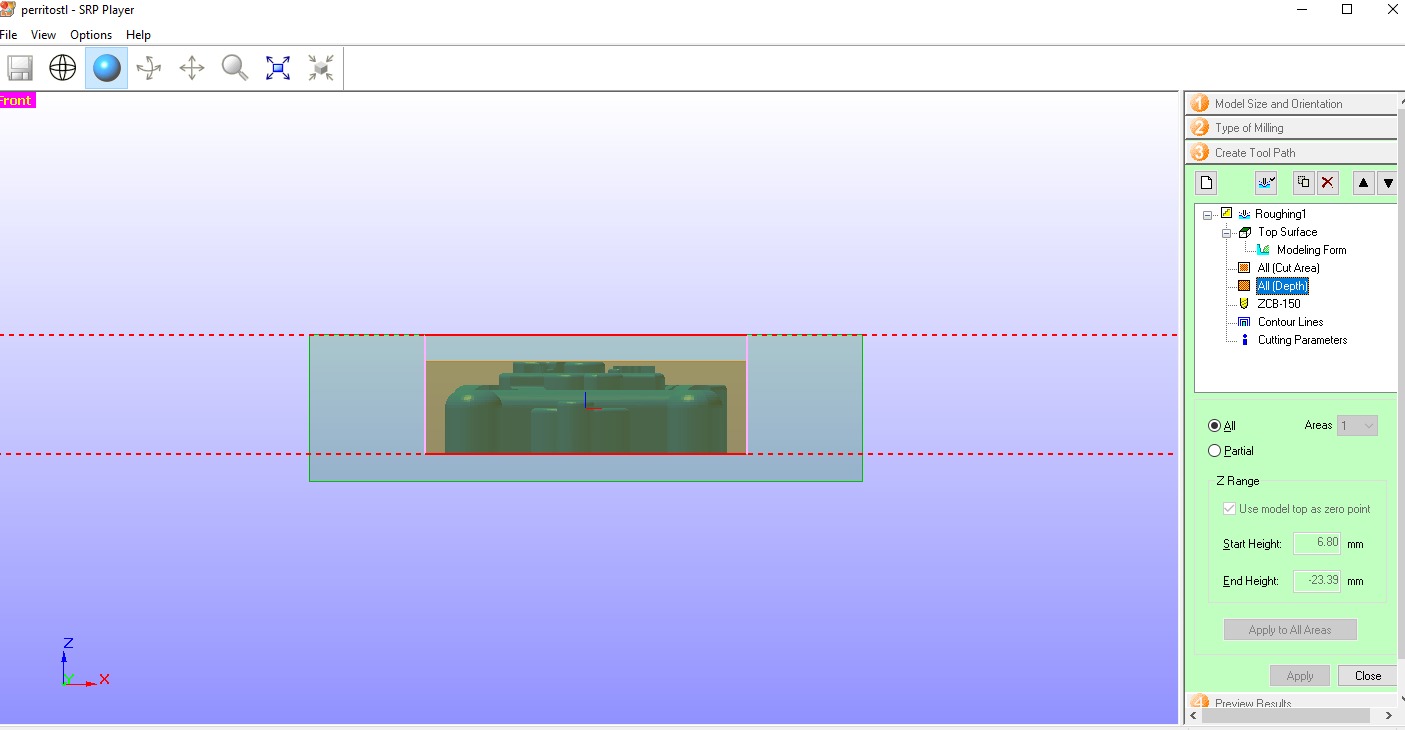
Z range / cut depth
Cutting depth set to All: Start 6.80 mm down to −23.39 mm, covering the full depth of the figure cavity.
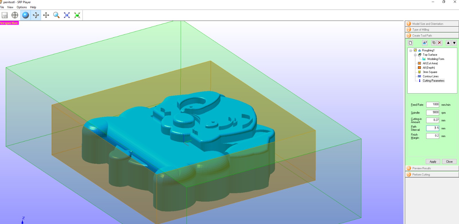
Roughing cutting parameters
Leaves a 0.20 mm finish margin. Surface looks rough and steppy — that is normal at this stage.
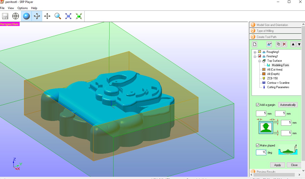
Finishing area & draft angle
5 mm margin, Contour + Scanline strategy. "Make sloped" at 10° — every wall tapers outward for clean silicone release.
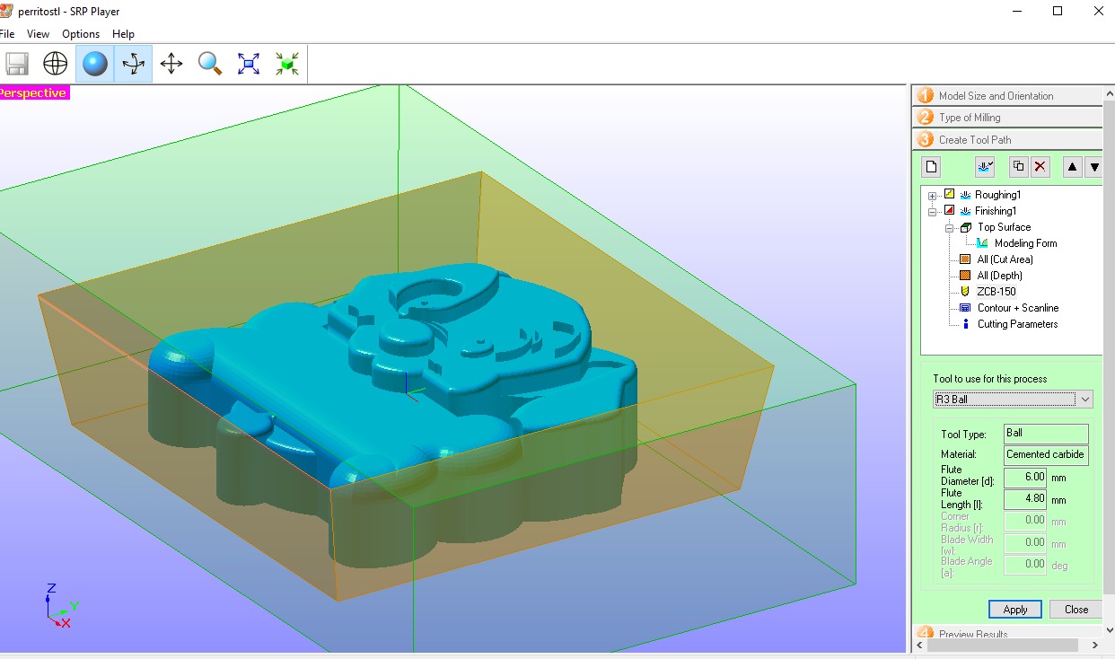
Tool: R3 Ball end mill
Ball end mill follows curved surfaces without leaving flat steps — essential for the smooth finish the mold needs.
Finishing parameters
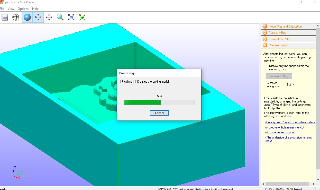
Generating the toolpath preview
SRP Player processing the finishing toolpath — shown at 52%, estimated total cutting time 9.3 hours.
Sending to the machine — Perform Cutting
Both Roughing1 (3mm Square) and Finishing1 (R3 Ball) confirmed in the Tool List. Clicked "Start Cutting".
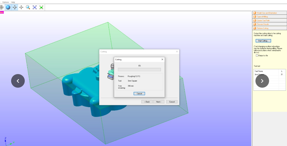
Cutting in progress
Roughing pass running — Process: Roughing1, Tool: 3mm Square, Time remaining: 256 min.
Physical Machine Setup — Roland MDX-540
Before starting the cut: fixing the block to the bed, zeroing the Z axis with the sensor, confirming READY state, and pressing ENTER to begin.
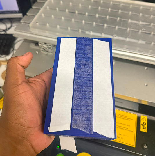
Double-sided tape fixturing
Two strips of double-sided tape on the underside of the blue wax block. Keeps the block from moving during the long roughing and finishing passes.
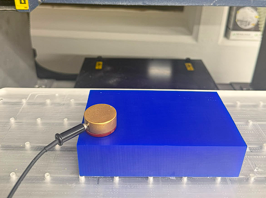
Z0 sensor — tool length sensing
Gold disk placed on top of the wax block. Z0 SENSE button brings the tool tip down until contact — sets Z zero reference on the material surface.
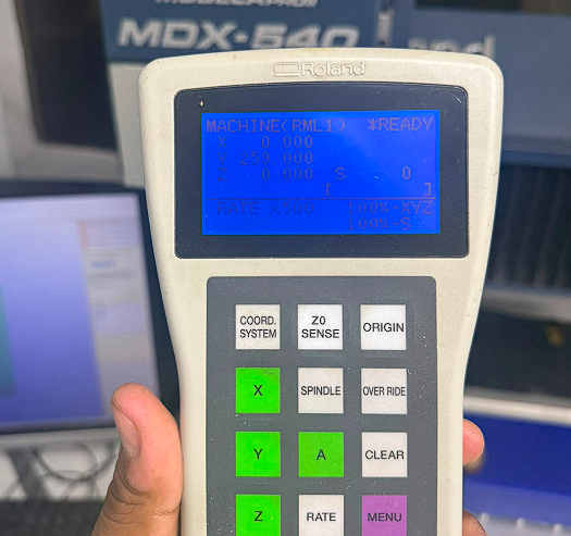
Controller — READY state
MACHINE(RML1) *READY with all axes zeroed. RATE ×500 at 100% XYZ and 100% S.
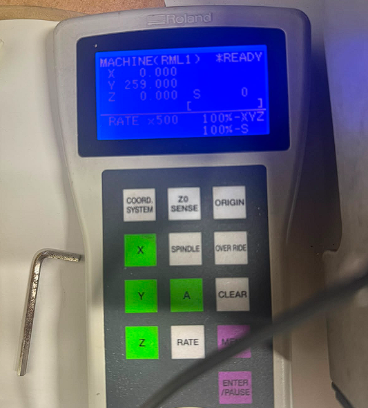
Controller on bench — READY confirmed
*READY status confirmed. Toolpath sent from SRP Player — waiting for ENTER to begin cutting.
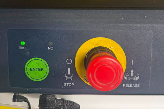
Front panel — ENTER to start
Green ENTER starts the cut. Red EMG STOP halts immediately. RML indicator green — machine communicating correctly.
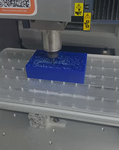
Roughing cut begins — MDX-540
3mm square end mill doing the roughing pass — fast parallel lines removing most waste material down to 0.20 mm above the final shape.
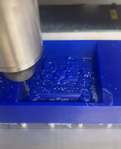
Roughing pass — close-up
Square end mill cutting through blue wax leaving the characteristic stepped surface. I vacuumed chips periodically to keep the cut area clean.
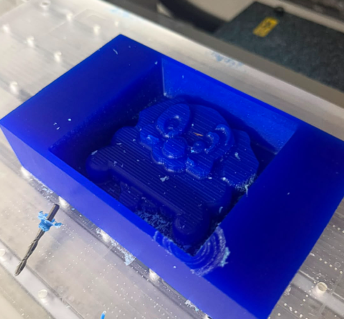
After roughing — figure emerging
Dog figure clearly visible but with step marks from the parallel toolpath — expected. The finishing pass with the ball end mill will smooth everything out.
Cleaning with compressed air
Compressed air blows all wax chips out of the cavities. The figure came out clean with all details sharp.
Making the Silicone Molds
Once the master mold was ready, I poured silicone into it to create the flexible molds for casting. The key steps: measure the correct ratio, pour slowly to avoid bubbles, and tap the mold on the table so bubbles rise to the surface before the silicone sets.
Measuring the correct amount — F-20 Plus
The photo shows the F-20 Plus base (large white jar) and its catalyst (small bottle) from Silicon Perú, alongside the blue wax block that will receive the silicone. Before pouring, I measured the exact quantity needed based on the mold volume.
The correct mix ratio for the F-20 Plus is:
- Base (Part A): 100 g
- Catalyst (Part B): 2–4 g (2–4% of base weight)
- Mix slowly until the color is fully uniform — avoid introducing air.
- Work time: ~20–30 minutes. Cure time: 4–6 hours at room temperature.
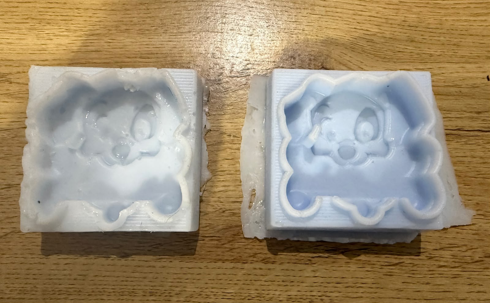
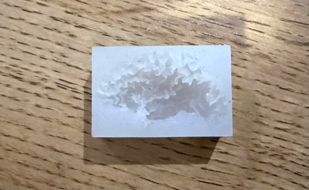
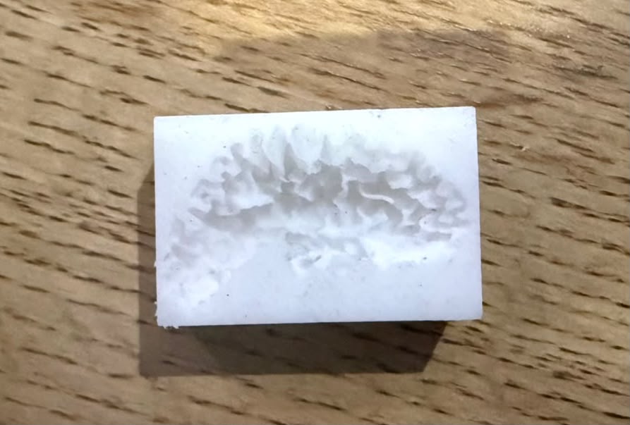
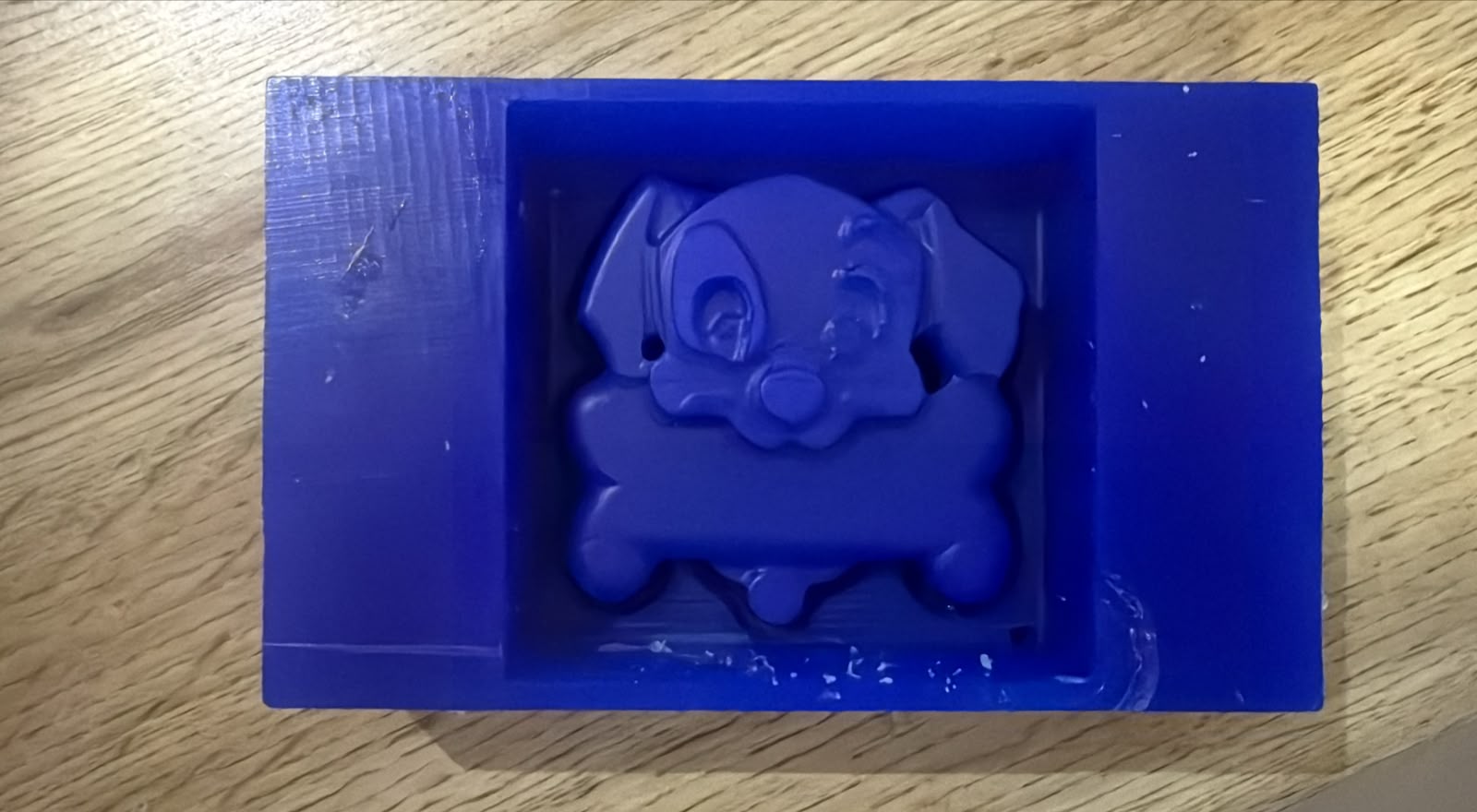
Left: no tapping — Right: tapped on the table
Both molds were poured from the same silicone batch. The difference is one technique applied after pouring:
- Left mold (no tapping): air bubbles remained trapped under the surface. The result shows pits, rough patches, and incomplete detail capture — especially visible around the dog's face and ears.
- Right mold (tapped): after pouring, I gave the mold several light taps on the table. The vibration brought bubbles up to the surface where they popped. The result is a clean, smooth cavity with all the detail from the wax master faithfully reproduced.
Takeaway: always tap the mold gently on the table for 30–60 seconds after pouring — it makes a significant difference in surface quality.
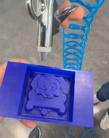
Video of the demolding process:
Peeling the cured silicone mold out of the wax master block.
Replace assets/MOLDING/demold_video.mp4 with your actual video filename.
Casting — Chocolate
I used the food-safe A-10 silicone mold for the chocolate cast. The chocolate was melted, poured, and left to cool before demolding.
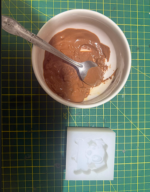
Melting the chocolate
Milk chocolate melted and stirred until fully smooth. The white A-10 silicone mold (food safe) placed ready beside it. Fully fluid chocolate avoids voids in the final piece.
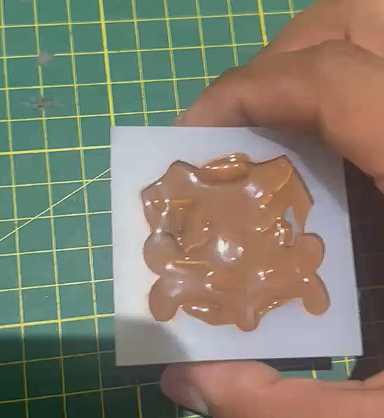
Pouring chocolate into the mold
Poured from a low height to avoid splashing. A spoon guided the pour into smaller detailed areas.
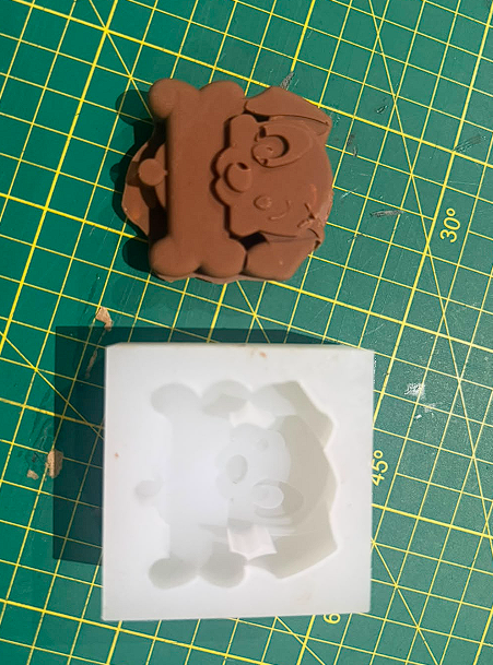
Demolded chocolate piece
Finished chocolate dog figure next to the A-10 mold. All details came out cleanly. No release agent needed for chocolate in food-safe silicone.
Results
Here are the final molds and cast pieces. The white silicone mold is A-10 (food safe). The brown piece is the chocolate cast.
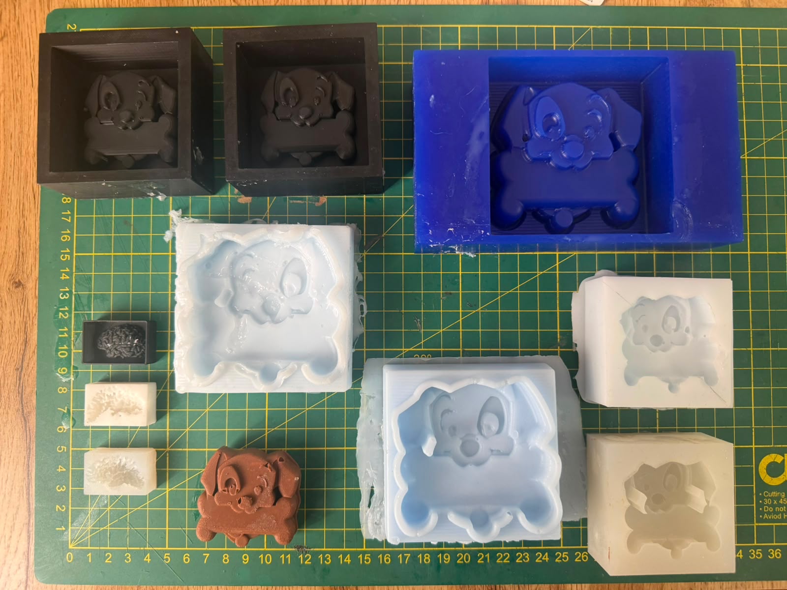
Final result: molds produced with different silicone materials and the cast chocolate piece.
Understanding Positive and Negative Molds
In molding and casting, positive and negative describe the relationship between the original form and the mold.
Problems and Solutions
Problem 01
Air bubbles got trapped in the silicone mixture while pouring.
Solution 01
Pour slowly in a thin stream from a height, tap the mold on the table after pouring to bring bubbles up.
Problem 02
First silicone mix came out too stiff — proportions weren't right.
Solution 02
Follow the exact ratio from the technical data sheet: 78g silicone + 2g catalyst.
Problem 03
Resin piece stuck to the silicone and came out damaged on demolding.
Solution 03
Always apply a release agent to the mold before pouring resin. Without it the resin bonds to the silicone surface.
Problem 04
Silicone was hard to remove from the master mold — walls too vertical.
Solution 04
Always add a taper angle (8–10°) to the walls in Inventor so the mold releases cleanly.
Project Downloads
All files related to the design and fabrication of this week's assignment: