Assignments
Assignment
Group assignment
- Design a machine that includes mechanism + actuation + automation + application.
- Build the mechanical parts and operate it manually.
- Actuate and automate your machine.
- Document the group project.
Individual assignment
- Document your individual contribution.
01. CNC Drawing Machine
02. Description
This week was dedicated to the design and construction of a complete machine as a group project. The challenge was to integrate four disciplines into a single functioning system: a mechanical structure, an actuation system (stepper motors), an electronic control layer (Arduino + GRBL firmware), and a software workflow (Inkscape, G-code, Universal Gcode Sender). We chose to build a three-axis CNC machine, a cartesian router capable of milling and engraving, motivated by its direct relevance to the tools and processes we work with daily in the Fab Lab.
The assignment required us to design every component digitally before fabricating it, manufacture the parts using the machines available in our lab (metal cutter, 3D printer, drill press), assemble the full structure, wire and configure the electronics, and document the complete process both individually and as a group. The machine structure uses aluminum profiles as side supports and vertical lateral reinforcements, with transparent acrylic panels at the front and back.
Andres Mamani
Contributed to the 3D modeling of the CNC machine in Inventor and prepared the technical drawings. Supported the assembly process and contributed to the development of the control code. Guided key decisions based on experience with the tools, materials, and machines used.
Micaela Córdova
Contributed to the design of parts and adapted models based on material measurements. Supported manufacturing and assembly, especially in fabricating metal components. Performed physical testing, ensured proper fitting, and prepared presentation materials including slides, video, and documentation.
Project Schedule
Planned sequence of activities across the two weeks, from initial research through final documentation. Tasks are colour-coded by discipline.
| Task | Week 1 | Week 2 | ||||||||
|---|---|---|---|---|---|---|---|---|---|---|
| Mon | Tue | Wed | Thu | Fri | Mon | Tue | Wed | Thu | Fri | |
| Research & References | ||||||||||
| 3D Modeling (Inventor) | ||||||||||
| Technical Drawings (DXF) | ||||||||||
| Parts Procurement | ||||||||||
| Metal Cutting | ||||||||||
| Drilling & Finishing | ||||||||||
| Laser Cutting | ||||||||||
| Mechanical Assembly | ||||||||||
| Electronics Wiring | ||||||||||
| GRBL / G-code Setup | ||||||||||
| Testing & Calibration | ||||||||||
| Documentation & Presentation | ||||||||||
03. Project Idea & Inspiration
At the beginning, we were unsure about which machine project to develop. After researching different possibilities, including a delta robot, a plotter, and a pick-and-place system, we decided to build a CNC machine due to its versatility and relevance in digital fabrication. A CNC machine can mill, engrave, and cut, and it directly uses many of the tools and concepts we have studied throughout the course.
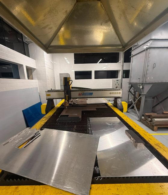
We were inspired by a small commercial CNC machine available in our laboratory, which helped us understand the basic structure and functionality of this type of system.
One of the most valuable resources was a series of video tutorials by Prof. García (CNC Fácil de Hacer en Casa). These covered the complete construction process, step-by-step assembly, motion system setup, and calibration considerations. Based on these references, we adapted the process to our own context, adjusting dimensions, materials, and fabrication methods according to the resources available in our lab.
System Workflow
The diagram below summarises the complete workflow of the CNC system, from vector design in software through to physical motion.
Vector Design
Create vector design, export as SVG or DXF.
Toolpaths
Convert design to toolpaths via Inkscape extension.
Stream
Stream G-code to Arduino over USB.
Firmware
Interprets G-code, outputs step/direction signals.
A4988
Convert step signals to stepper motor current.
Lead Screws
Stepper motors drive lead screws along X, Y, Z.
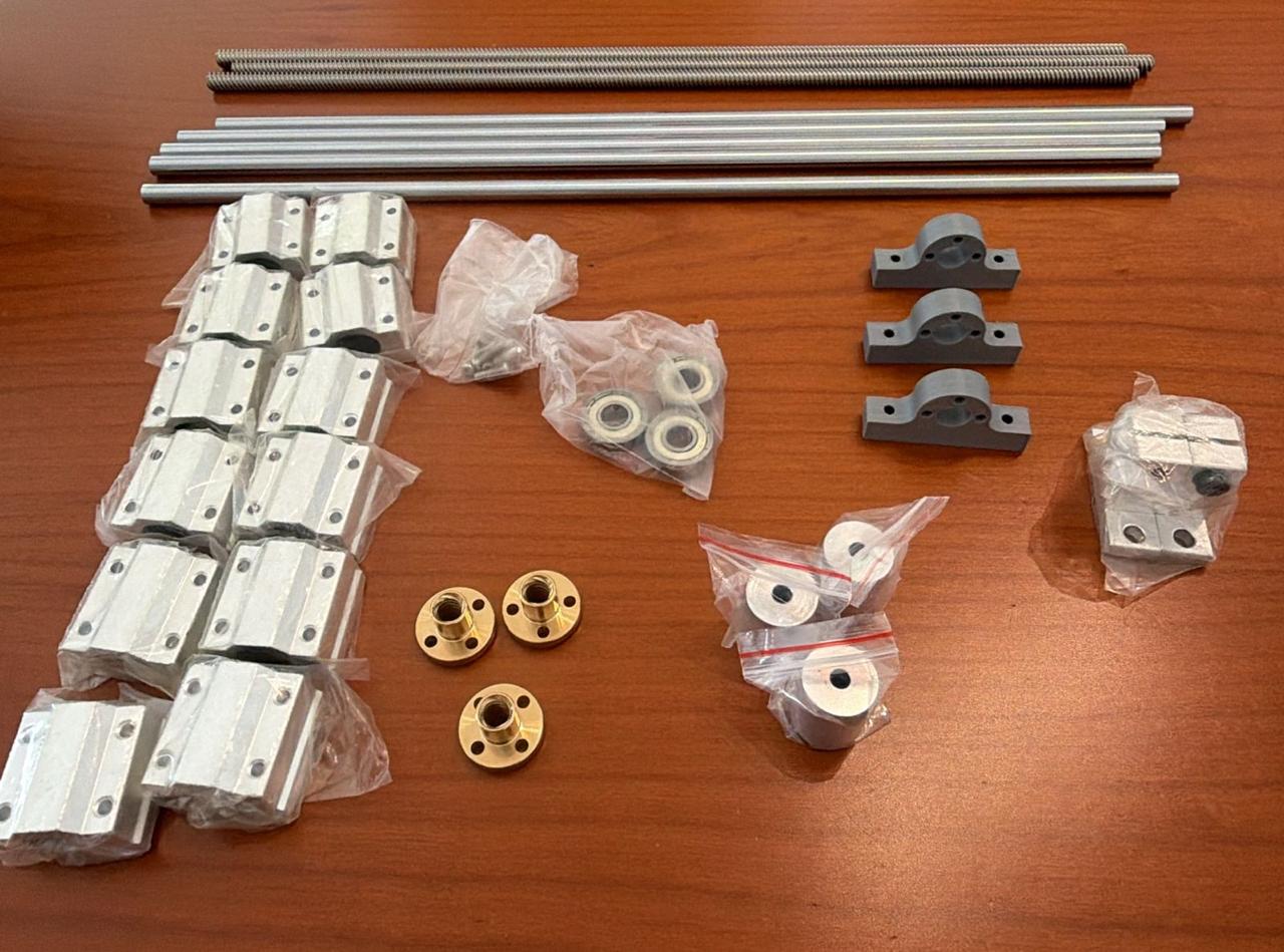
Main Components
Mechanycal
| Component | Qty | Spec | Function |
|---|---|---|---|
| Flexible shaft coupling | 3 | 8 mm bore | Connect motor shaft to lead screw |
| Lead screw + nut + sleeve | 3 | 8 mm Ø, ~40 cm | Convert rotation to linear motion |
| Linear ball bearings (LM8UU) | 12 | 8 mm | Smooth and precise linear guidance |
| Hardened steel shafts | 5 | 8 mm Ø, ~40 cm | Guide rails for each axis |
| Shaft supports | 2 | 8 mm | Align and stabilize shaft ends |
| Standard bearings | 3 | 608 ZZ | Support rotating lead screw ends |
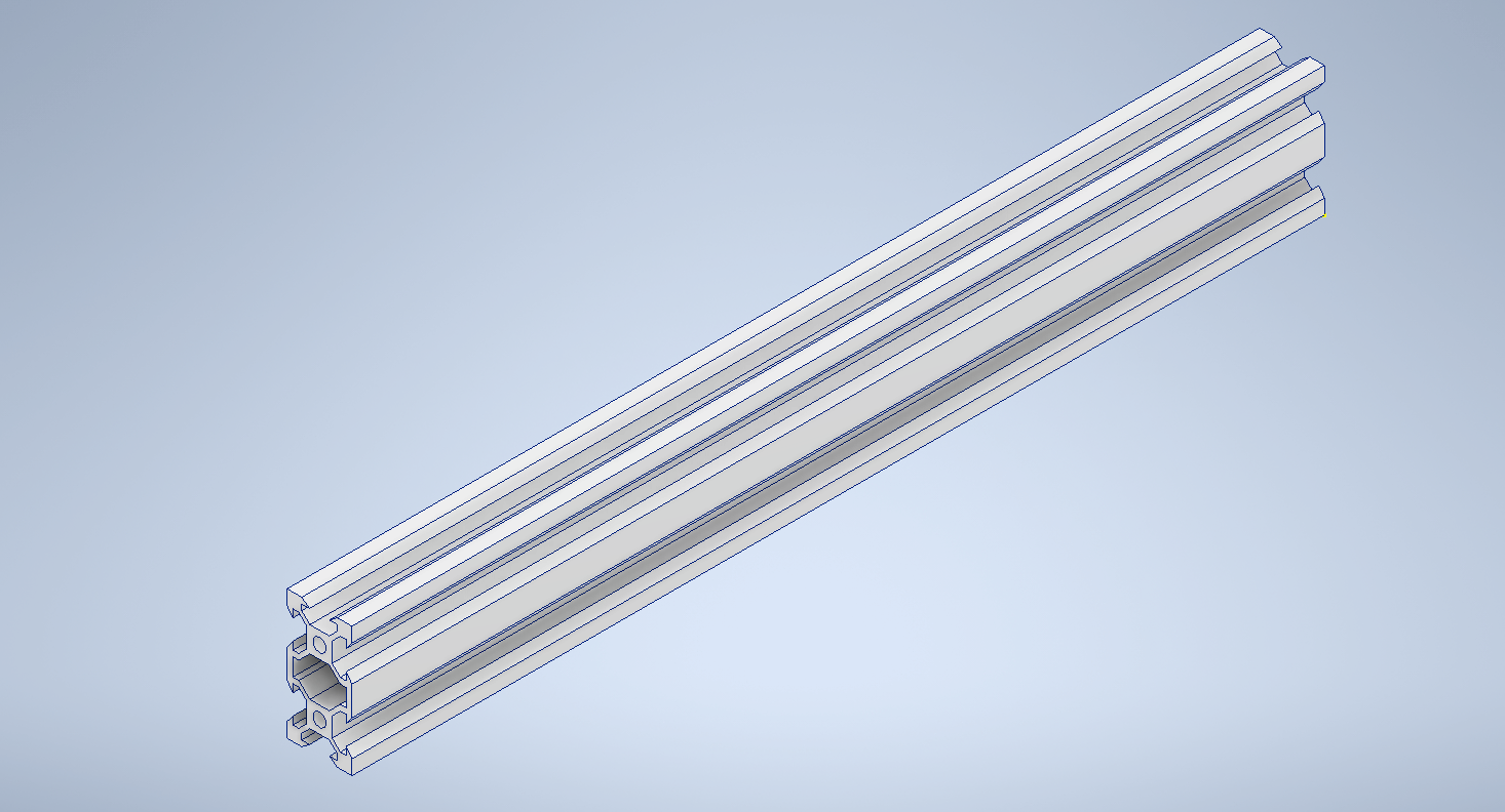
| Aluminum profiles (side supports) | — | 20×20 mm | Main structural frame, lateral vertical supports |
| Transparent acrylic panels | 2 | 3 mm | Front and back enclosure panels |
| Fasteners (M3 screws, nuts, spacers) | — | — | Assembly hardware |
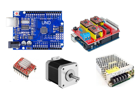
Electronics
| Component | Qty | Notes |
|---|---|---|
| Arduino Uno (running GRBL) | 1 | Main motion controller |
| CNC Shield v3 | 1 | Mounts on Arduino, routes signals to drivers |
| A4988 stepper drivers | 3 | Microstepping up to 1/16 |
| Stepper motors (NEMA 17) | 3 | X, Y and Z axes |
| Power supply 12V / 5A | 1 | Provides energy to the system |
Software
| Tool | Purpose |
|---|---|
| Inkscape | Create and vectorize designs; generate G-code toolpaths via extension |
| Universal Gcode Sender | Send G-code instructions to the machine via USB |
| GRBL firmware | Runs on Arduino; interprets G-code and outputs step/direction signals |
| Autodesk Inventor | 3D modeling and technical drawing export |
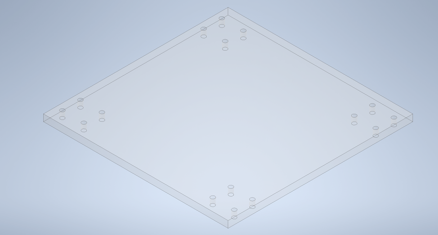
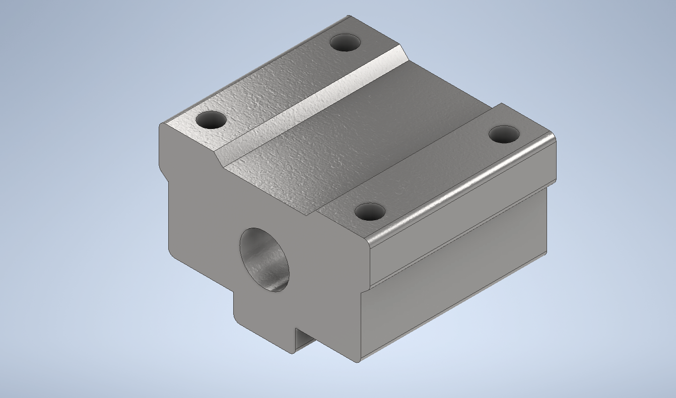
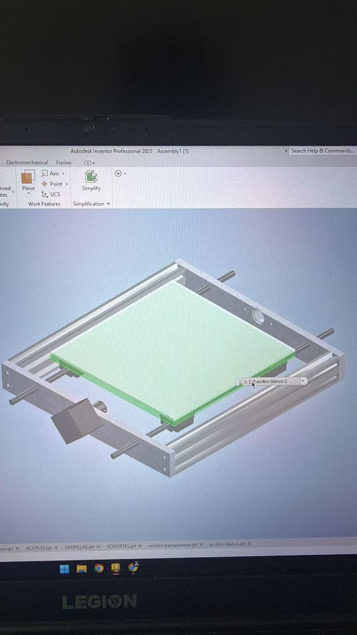
04. The Design
Before manufacturing any physical part, we modeled the entire machine in Autodesk Inventor. This step was essential: it allowed us to visualize the spatial relationships between all components, detect dimensional conflicts early, and generate precise 2D drawings ready for fabrication. The design uses aluminum profiles as the main lateral and vertical structural supports, with transparent acrylic panels at the front and back. Each component was modeled as a separate part file and then brought together in a master assembly file.
The 3D model also served as the reference for material and dimension decisions. Since hardware (lead screws, bearings, shafts) had to be sourced locally, some dimensions were adjusted after procurement to match the actual measured sizes of purchased parts.
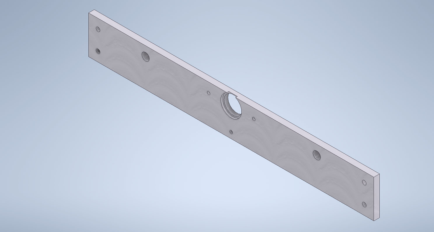
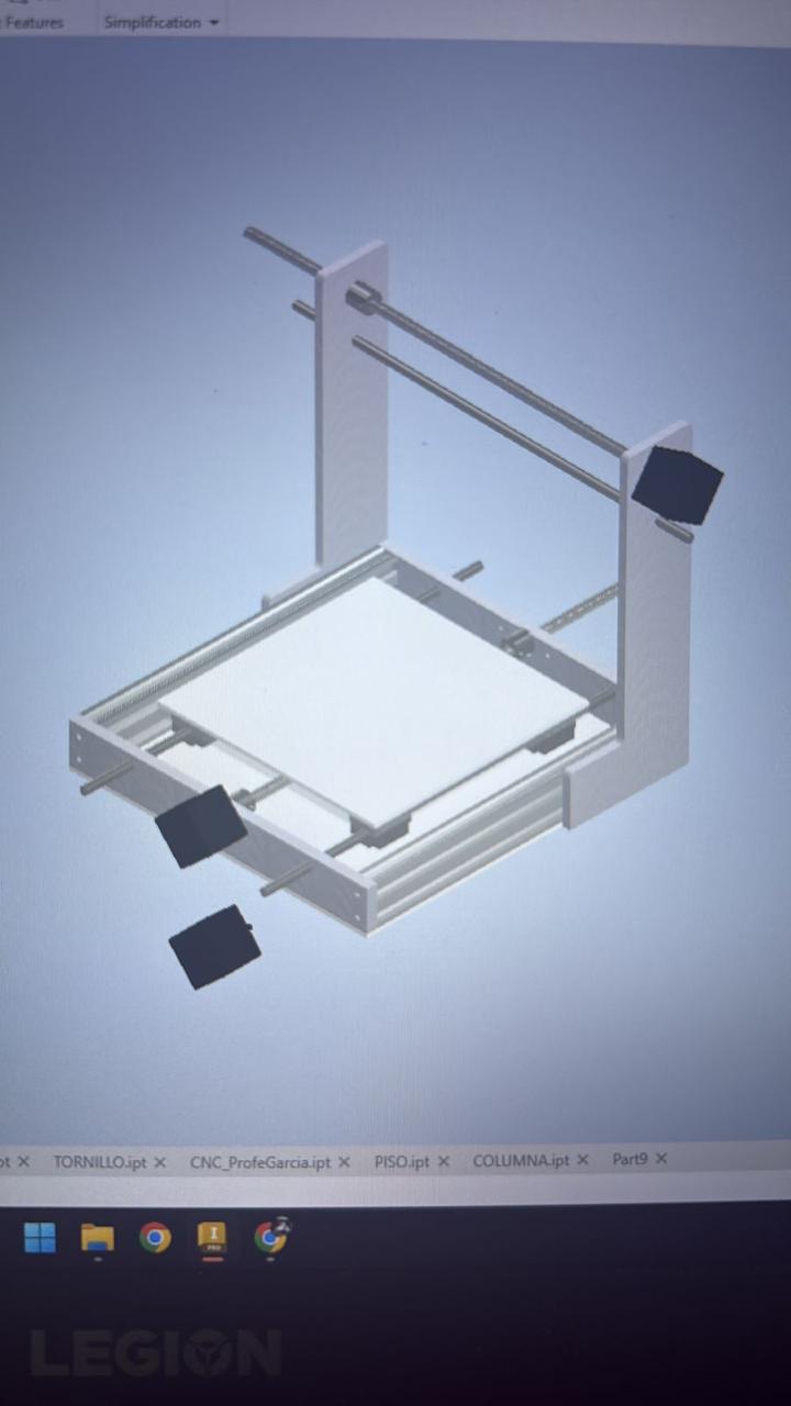
Inventor Modeling Process
Progressive stages of the model, from the first individual components through to the complete assembly.
Once the assembly was complete, we exported 2D technical drawings in DXF format directly from Inventor. These files were used as cutting guides for both the laser cutter and the metal cutting machine.
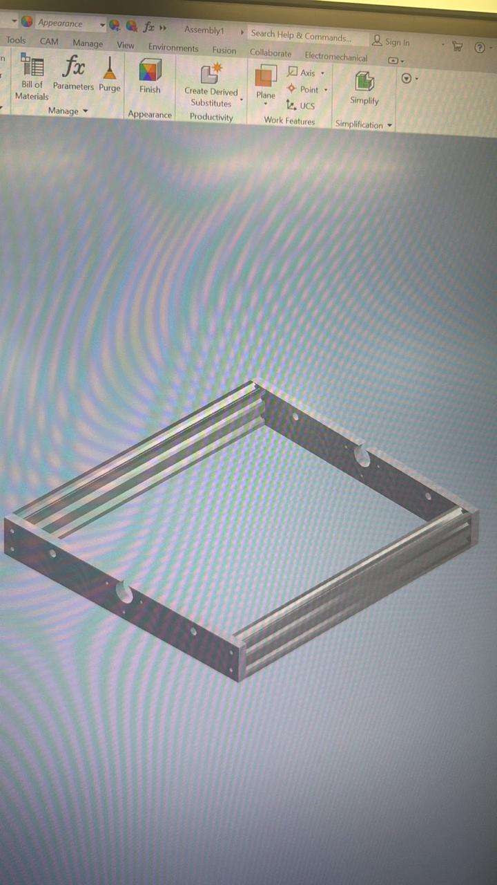
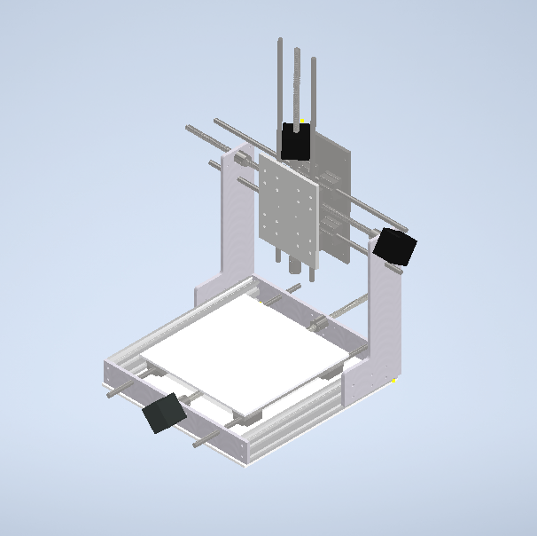
Assembly Views
The completed machine from different angles in Inventor, illustrating how each axis sub-system connects to the overall structure.
06. Mechanical Fabrication
With the 3D model finalized and all components verified, fabrication began. The structural plates were cut from aluminum flat stock using the metal cutting machine, following the DXF profiles exported from Inventor.
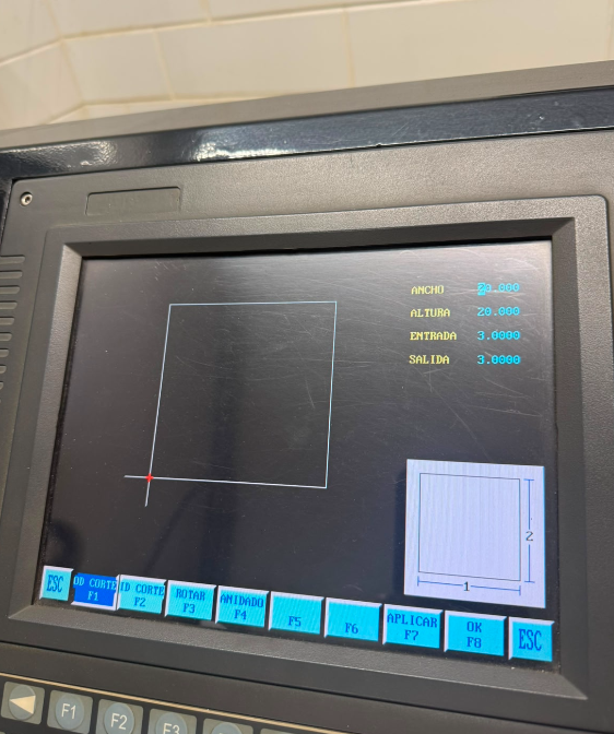
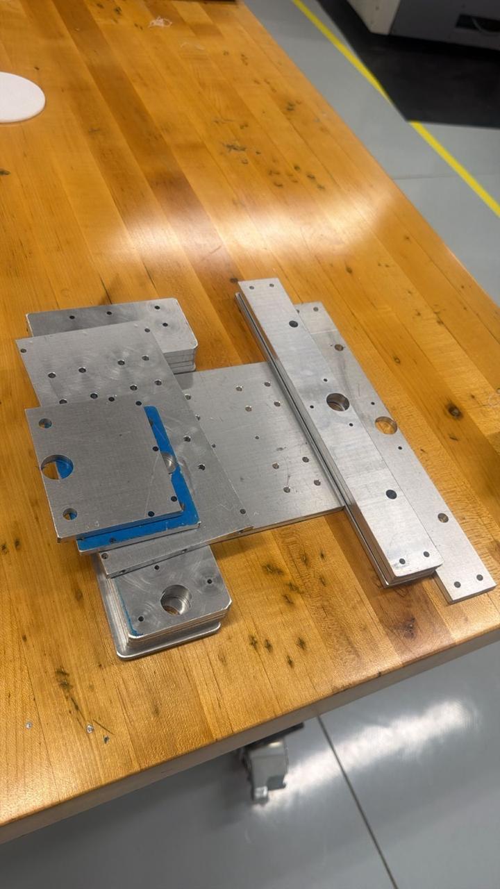
Metal Cutting
Base plates, axis carriages, and motor mounts cut from aluminum sheet. Multiple passes to maintain accuracy and reduce tool wear.
08. Results & Final Machine
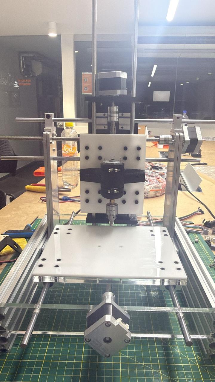
After assembly, we ran the first motion tests manually, moving each axis by hand to verify smooth travel and absence of binding. We then connected the electronics, flashed GRBL onto the Arduino, and configured the axis steps-per-mm values.
Early test
Final Machine
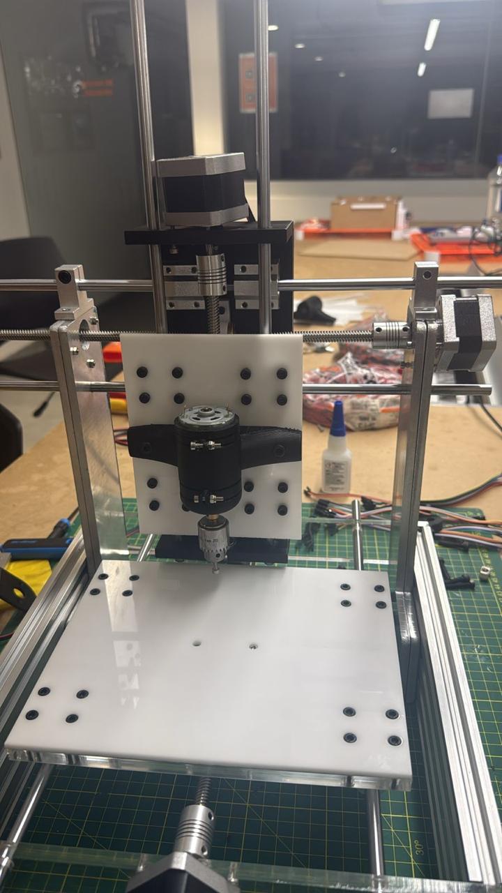
CNC Drawing Machine, final assembled machine.
Demo Video
Project Downloads
Download all files