Assignments
Assignment
Group assignment
- Measure the power consumption of an output device.
Individual assignment
- Add an output device to a microcontroller board you've designed, and program it to do something.
Summary - Group Assignment
During the group assignment, we tested a DC motor using different duty cycles and measured current, voltage, and power. We observed that higher duty cycles improve motor performance, while low values are not enough to start movement.
We measured the current, voltage, and power consumption at each duty cycle level. Through this process, we understood how the electrical behavior of a motor changes depending on the PWM signal and the mechanical load applied.
These experiments allowed us to analyze the relationship between control signals and real energy consumption, which is essential when designing systems that depend on motor-driven actuators.
Visit Group Assignment Page →
Simulation Before Physical Testing
Before building the physical circuit, I first tested the system in a simulation environment to validate the behavior of the motor and the LED. This allowed me to confirm that the code logic was correct and that both elements responded properly before working with real components.

In the simulation, the motor was controlled using PWM through pin 9, while the LED on pin 7 acted as an indicator. When the motor was active, the LED turned on, and when the motor stopped, the LED turned off. This helped visualize the system behavior clearly.
Code Used
int motorPin = 9;
int ledPin = 7;

void setup() {
  pinMode(motorPin, OUTPUT);
  pinMode(ledPin, OUTPUT);
}

void loop() {
  analogWrite(motorPin, 200);
  digitalWrite(ledPin, HIGH);
  delay(3000);

  analogWrite(motorPin, 0);
  digitalWrite(ledPin, LOW);
  delay(3000);
}
The motor (pin 9) is controlled using PWM and the LED (pin 7) acts as an indicator. When the motor turns on, the LED also turns on, and both turn off after 3 seconds. This cycle repeats continuously.
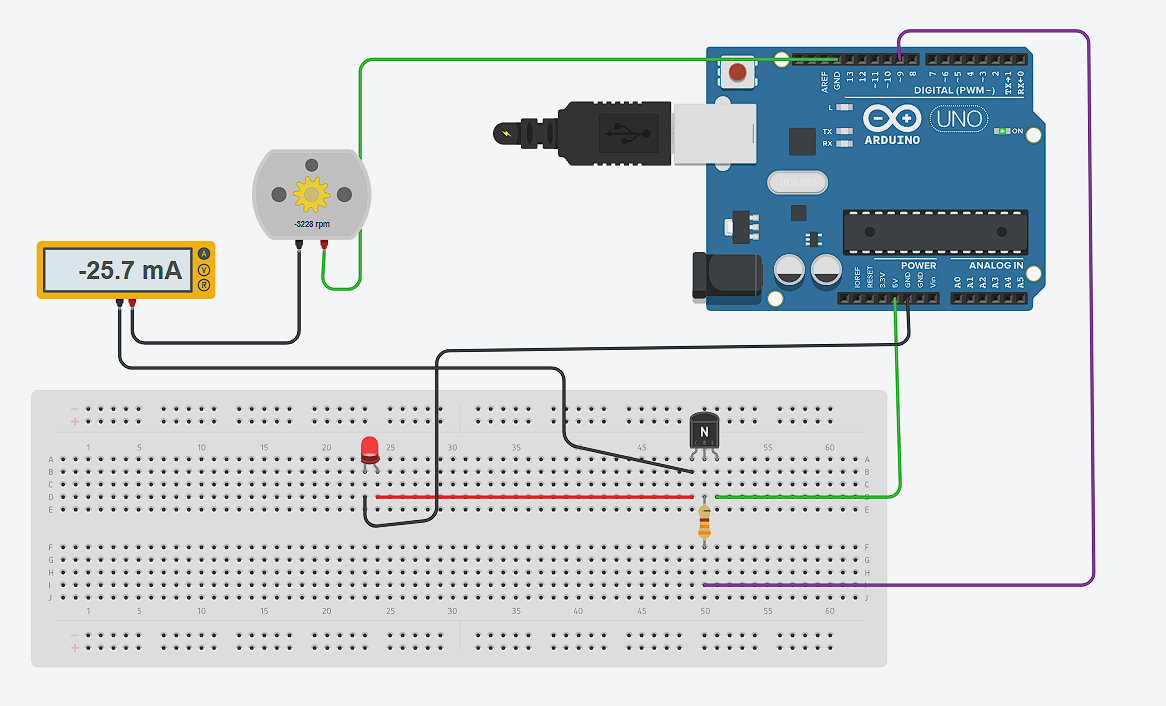
Electrical Measurements
During the simulation, I also reviewed how to correctly measure electrical values. To measure current, the ammeter must be connected in series, meaning it becomes part of the current path. This ensures that all the current flowing to the motor passes through the measuring device.
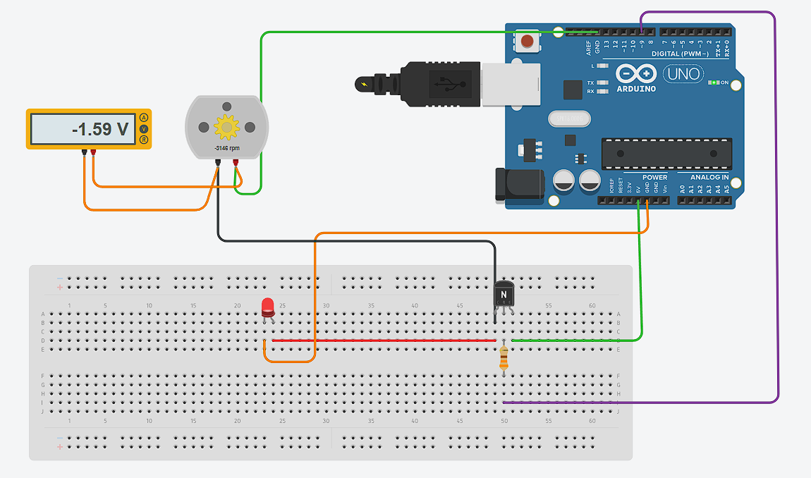
To measure voltage, the voltmeter must be connected in parallel across the motor terminals. This allows measuring the potential difference without interrupting the circuit.
Duty Cycle vs Motor Performance
| Duty Cycle | Current (A) | Voltage (V) | Power (W) | Observation |
|---|---|---|---|---|
| 50% | 0.042 | - | - | Not enough to move the motor |
| 65% (Minimum) | 0.084 | 1.389 | 0.1167 | Motor starts moving |
| 75% | 0.120 | 1.38 | 0.1656 | Stable operation |
| 82.5% (Average) | 0.122 | 4.2 | 0.5124 | Smoother and stronger performance |
| 100% | 0.150 | 7.15 | 1.0725 | Maximum power |
Load and Motor Behavior
During testing, it was also observed that when applying physical pressure or load to the motor, the current consumption increased. This happens because the motor needs to generate more torque to overcome the external resistance. As a result, the driver supplies more current from the power source to maintain the rotation.
This behavior shows that the motor does not consume a fixed amount of current. Instead, it dynamically adjusts depending on the mechanical load. When the load increases, the motor demands more energy, which is reflected as an increase in current and power consumption.
Individual Assignment – Actuator Selection and Testing
For this week, I initially planned to use a servomotor as the main actuator, since I wanted to generate controlled movement for the tentacles of my project. Servomotors provide precise angular control, which seemed suitable for articulated motion.
The microcontroller board used throughout this assignment was designed and fabricated in previous weeks — see Week 7 – Electronics Design for the design process and Week 8 – Electronics Production for the fabrication.
Output Device 1: Servo Motor Control with LED Indicator
In this test, a servo motor is controlled using pin D0, while an LED connected to pin D9 is used as a visual indicator. The servo moves between different angles (0°, 90°, and 180°), and the LED turns on while the movement is happening.
#include <Servo.h>

Servo miServo;

int servoPin = D0;
int ledPin = D9;

void setup() {
  miServo.attach(servoPin);
  pinMode(ledPin, OUTPUT);
}

void loop() {
  miServo.write(0);
  digitalWrite(ledPin, HIGH);
  delay(2000);

  miServo.write(90);
  delay(2000);

  miServo.write(180);
  delay(2000);

  digitalWrite(ledPin, LOW);
  delay(2000);
}
The servo motor position is controlled using angle values, while the LED provides feedback by indicating when the system is active. This helps visualize the actuator behavior during testing.
Output Device 2: Air Pump (Air Compressor) Control with LED Indicator
However, after analyzing the requirements of my design, I decided to change the approach. Instead of rigid movement, I opted for a pneumatic solution using an air pump. This allows generating softer and more organic motion by inflating flexible structures, which aligns better with the concept of soft robotics.
In this test, the air compressor is controlled through two digital pins, D0 and D1, while an LED connected to D9 is used as a visual indicator. The driver receives the control signals from the microcontroller, and the LED turns on when the compressor is active.
int motorPin1 = D0;
int motorPin2 = D1;
int ledPin = D9;

void setup() {
  pinMode(motorPin1, OUTPUT);
  pinMode(motorPin2, OUTPUT);
  pinMode(ledPin, OUTPUT);
}

void loop() {
  // Compressor ON
  digitalWrite(motorPin1, HIGH);
  digitalWrite(motorPin2, LOW);
  digitalWrite(ledPin, HIGH);
  delay(3000);

  // Compressor OFF
  digitalWrite(motorPin1, LOW);
  digitalWrite(motorPin2, LOW);
  digitalWrite(ledPin, LOW);
  delay(3000);
}
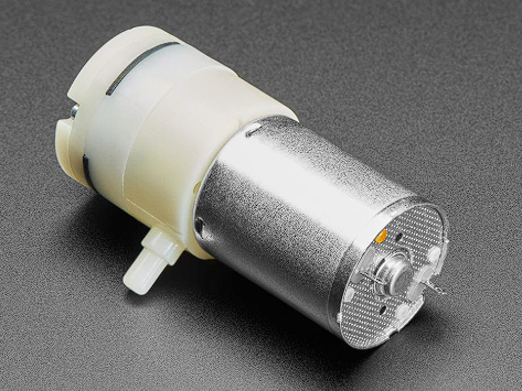
Air Pump – Physical Component
Below is the air pump used in this test. It is a small DC mini pump that generates enough pressure to inflate soft silicone structures. It was powered through the L298N motor driver using a 9V battery.
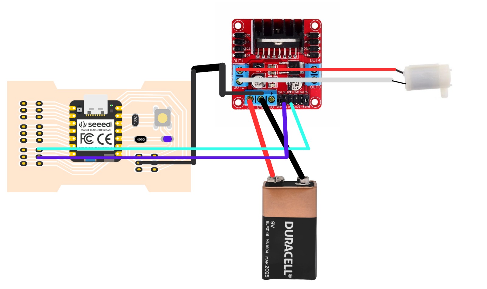
Wiring Connections
The diagram below shows the full connection between the XIAO nRF52840 microcontroller, the L298N motor driver, the air pump, and the 9V Duracell battery. The cyan wire connects D0 (IN1), the purple wire connects D1 (IN2), the red wire is the positive power line from the battery to the driver, and the black wire is the ground shared between all components.
Air Pump – Working Demo
The following video shows the air pump turning on and off, controlled by the XIAO nRF52840 through the L298N driver. The pump activates for 3 seconds and then stops, repeating the cycle continuously.
The compressor is activated by setting D0 HIGH and D1 LOW, which defines the motor direction through the driver. At the same time, the LED turns on to indicate that the actuator is working. After three seconds, both control pins are set LOW, stopping the compressor, and the LED turns off.
For this reason, I used an L298N motor driver to interface between the microcontroller and the air pump. The microcontroller sends control signals (digital or PWM), while the driver handles the power required by the actuator from an external power source. This ensures safe operation and proper performance of the system.
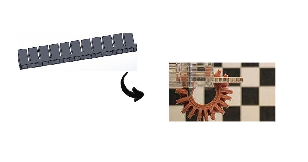
L298N Driver Components
Click each part to explore its function and structure.
1. L298N Chip
The main component of the module. It contains two H-bridges that allow bidirectional control of motors.
Through these tests, I confirmed that the driver supplies the necessary current depending on the load of the motor. This is especially important in my application, since the air pump behavior changes depending on the pressure and resistance of the system. Therefore, using a driver like the L298N allowed me to reliably control the actuator while protecting the microcontroller.
Problems Encountered
At the beginning, my goal was simply to activate the air pump without controlling its speed. For this reason, I only used the IN1 and IN2 pins of the driver to define the motor direction and basic ON/OFF behavior.
During this process, I learned an important detail about the L298N driver. If the ENA pin is not used for PWM control, it must be enabled manually using a jumper. Otherwise, the driver will not activate the motor outputs, and the system will not work.
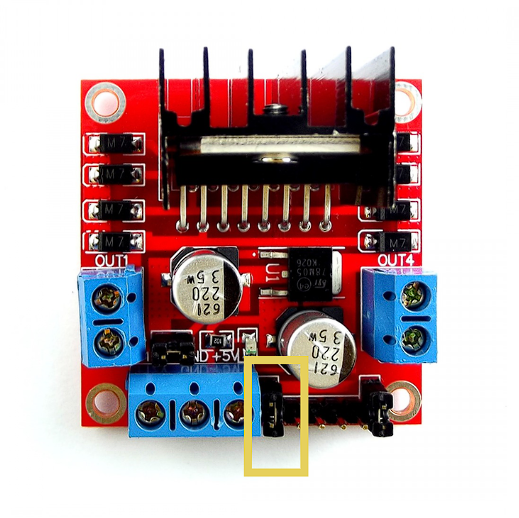
This means that ENA acts as an enable signal for the motor channel. Without it being HIGH (either through PWM or a jumper), the driver remains disabled even if IN1 and IN2 are correctly configured.
Project Downloads
Download all files