Week 3 Progress Checklist
| Status | Task |
|---|---|
| ✓ | Linked to the group assignment page |
| ✓ | Reflected on your individual page what you learned of your labs safety training |
| ✓ | Explained how you created your parametric design |
| ✓ | Documented how you made your press-fit construction kit |
| ✓ | Documented how you made something with the vinyl cutter |
| ✓ | Included your original design files |
| ✓ | Included hero shots of your results |
Computer-controlled cutting
Group Assignment
Laser Cutting
1. Equipment overview
Laser cutting technology uses a focused laser beam to cut and shape materials with high precision. The process enables clean edges, complex geometries, and efficient production, making it widely used across industrial and manufacturing applications.
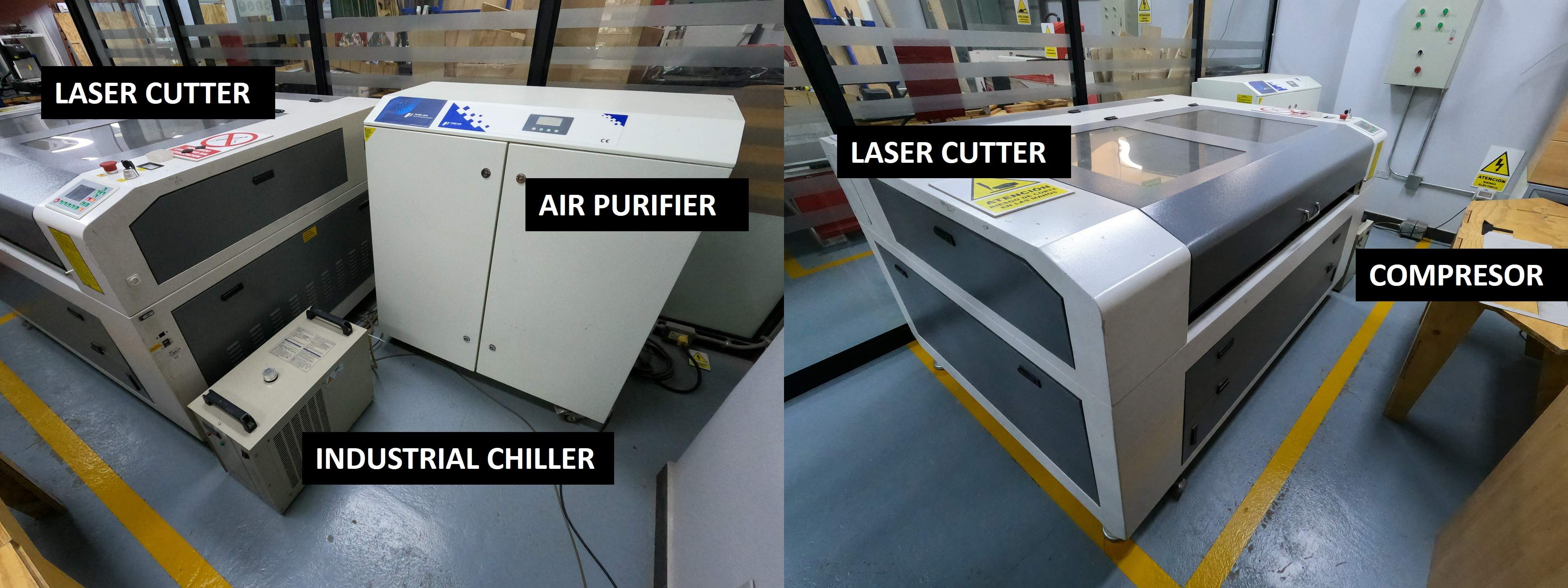
Laser Cutter Machine:
Supplier Link: KeyLand Laser
Model: KEYLAND LASER 1390
Working area: 1300x900 mm
Power:RECI W6 Tubo 130 W
2. Safety
When working with laser cutters, it is crucial to follow safety guidelines to prevent accidents and injuries. Always wear appropriate eye protection, ensure proper ventilation to avoid inhaling fumes, and never leave the machine unattended while it is operating.
- Never open the machine while it’s running.
- Do not bypass safety doors or interlocks.
- Don’t stare into the laser path or cutting area.
- Wear proper laser safety glasses only if instructed (usually for maintenance, not normal operation).
- Never leave the machine unattended while cutting.
- Know where the fire extinguisher is and how to use it..
3. Parameters
Key parameters for laser cutting include power, speed, and frequency. Adjusting these settings allows for precise control over the cutting process and material compatibility.
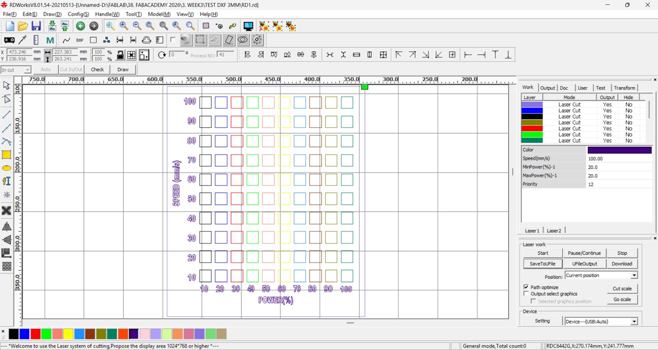
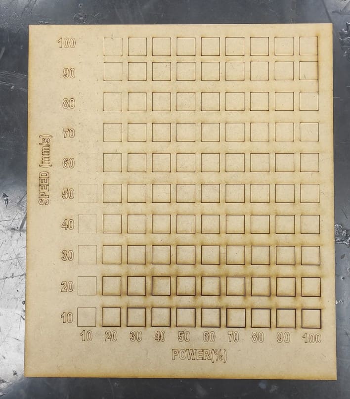
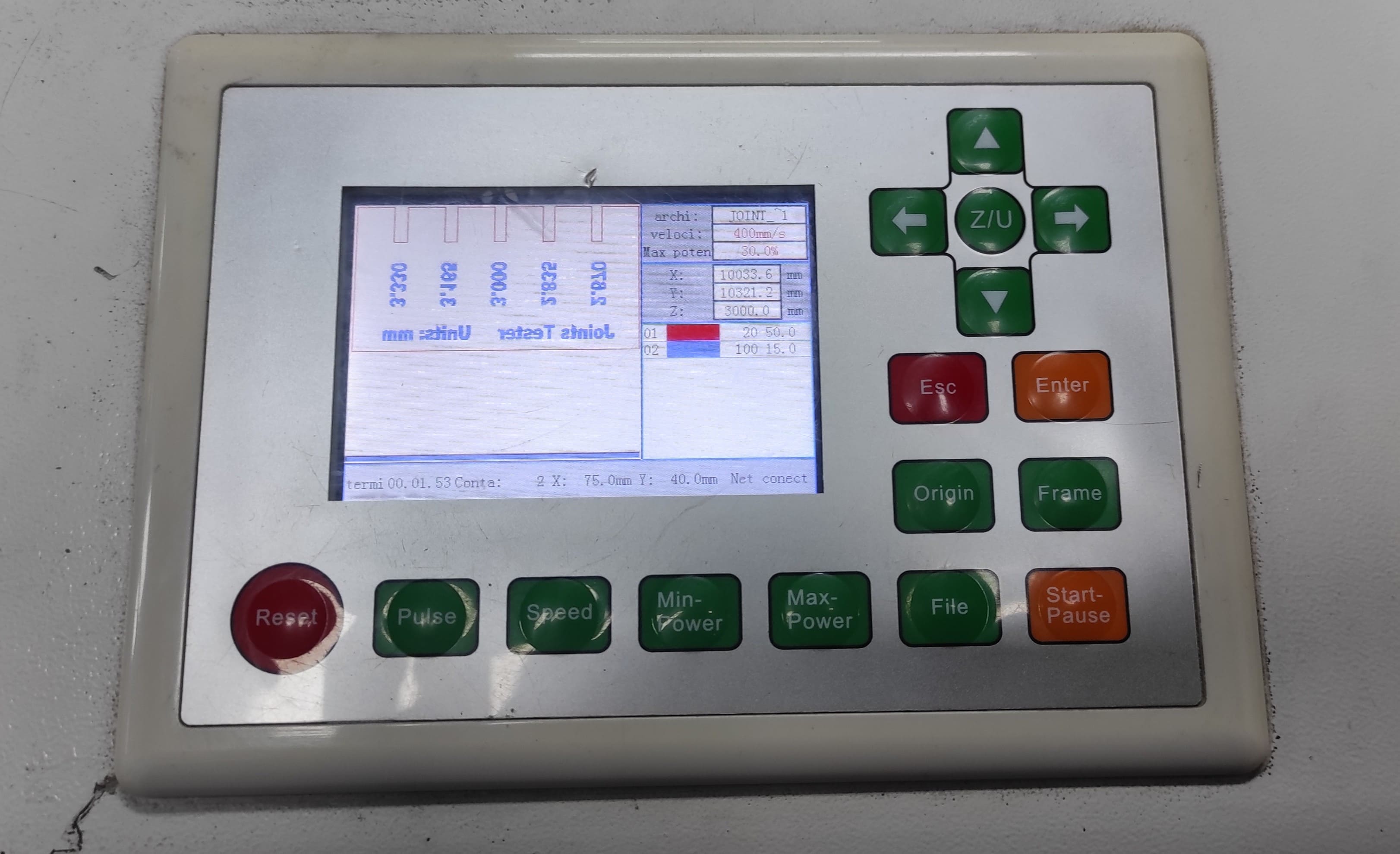
I prepared a table to test the values (power and speed) in order to determine the exact settings needed for 3 mm MDF. For that I used RDWorks to generate the cutting test table. For Power I considered values from 10% to 100% in increments of 10%, and for Speed I considered values from 10% to 100% in increments of 10%.
You can download RDWorks: Software RDWorks V8
Once I had the test table, I proceeded to use the laser machine to obtain the results.
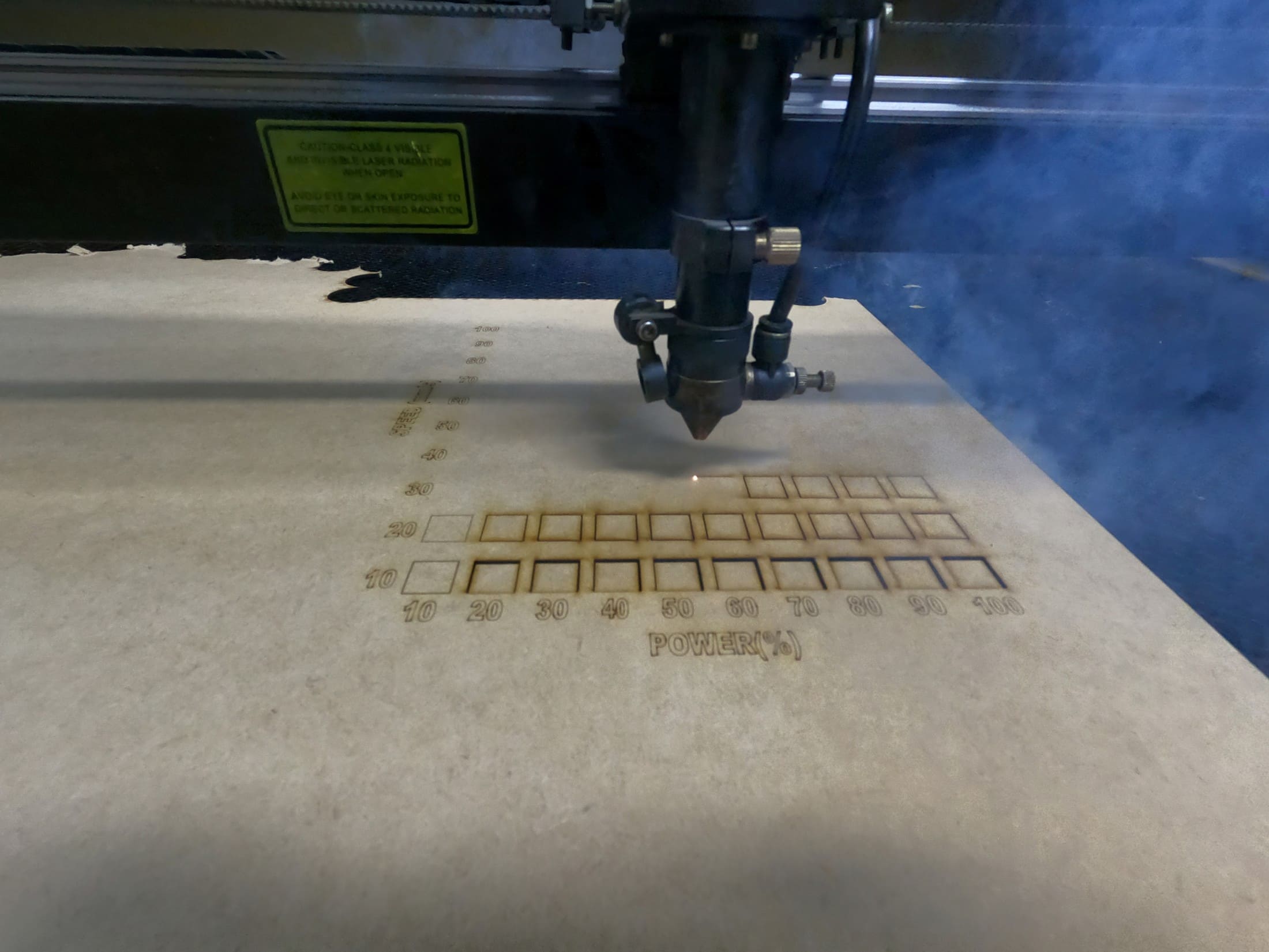
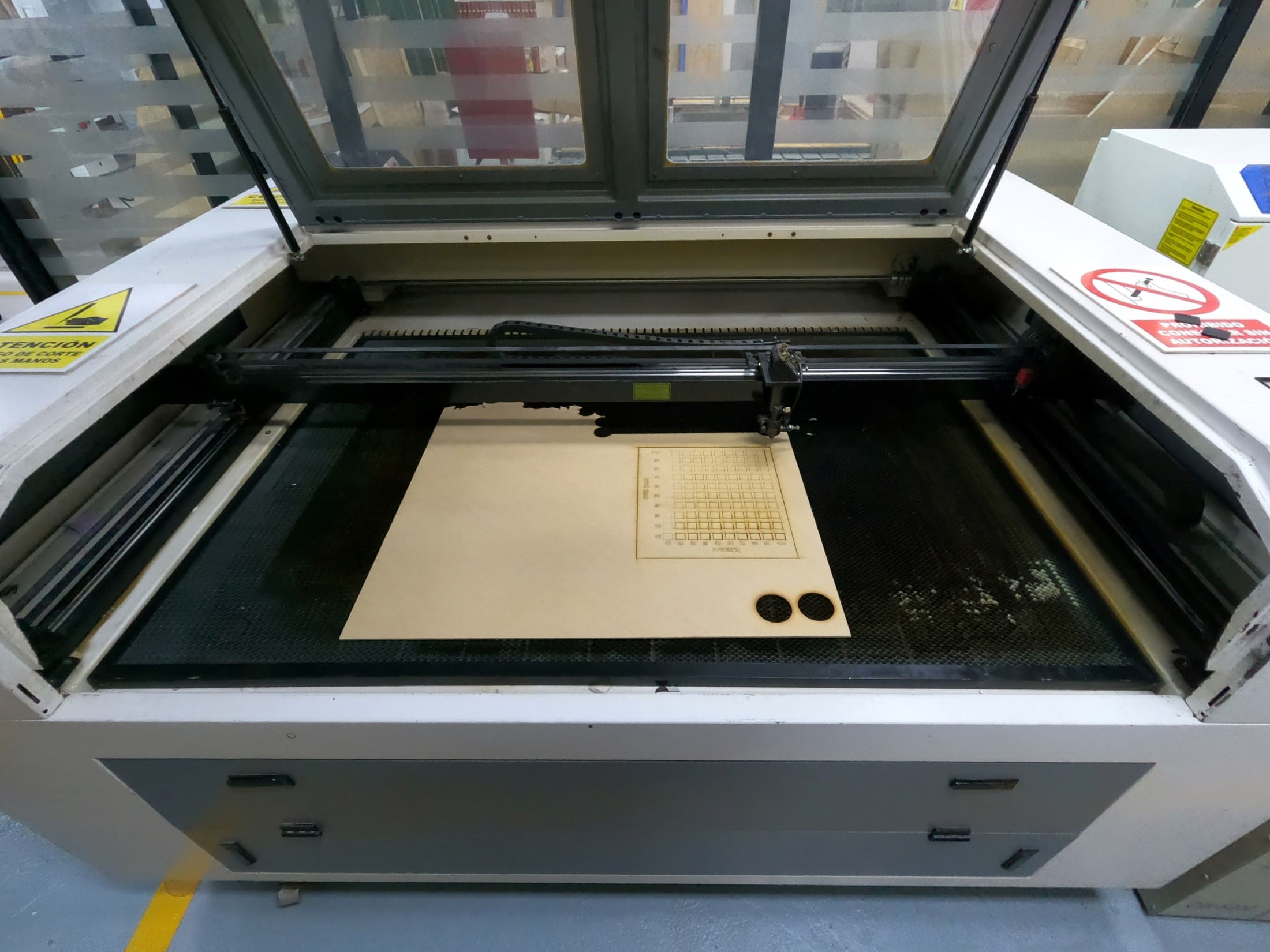
After testing different combinations of power and speed, I determined the optimal settings for cutting 3 mm MDF: Power at 50% and Speed at 20%.
4. Estimate for the notches
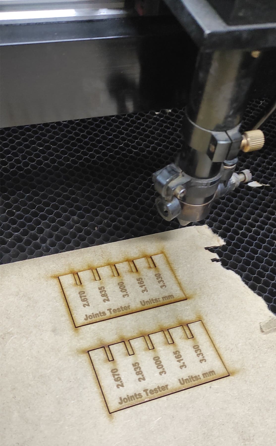
We recorded and saved the cutting parameters as a reference for cutting 3 mm MDF. Then, we measured the square and the hole using a vernier caliper.
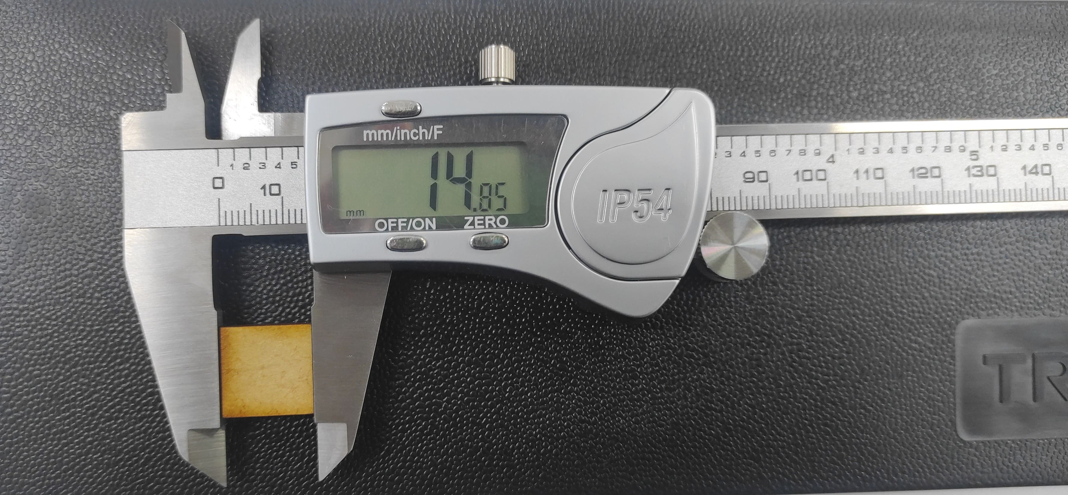
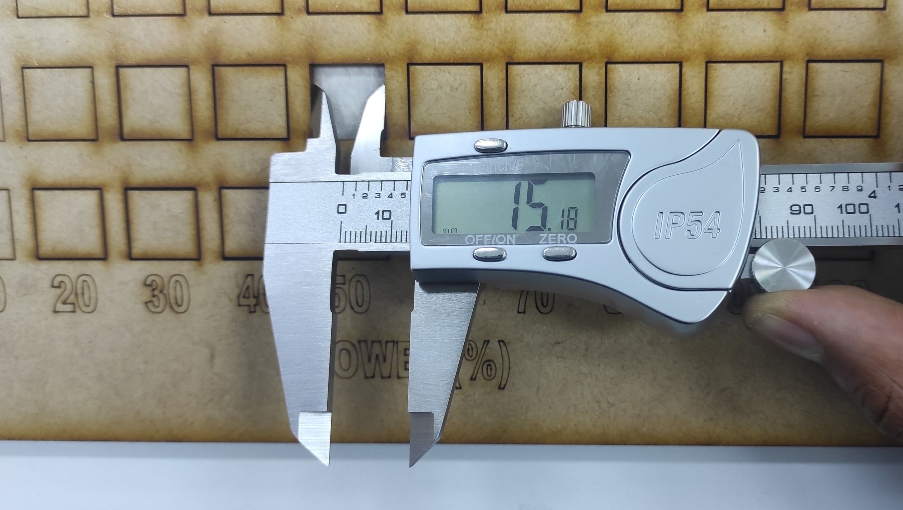
Subtract and divide by two, in my case it’s: (15.18-14.85)/2 = 0.165mm, I used these measurements to draw the estimate for the notches.
5. Press-fit notch
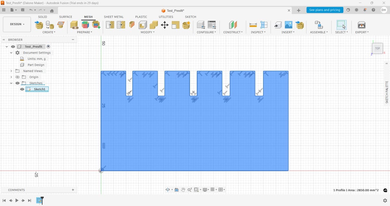
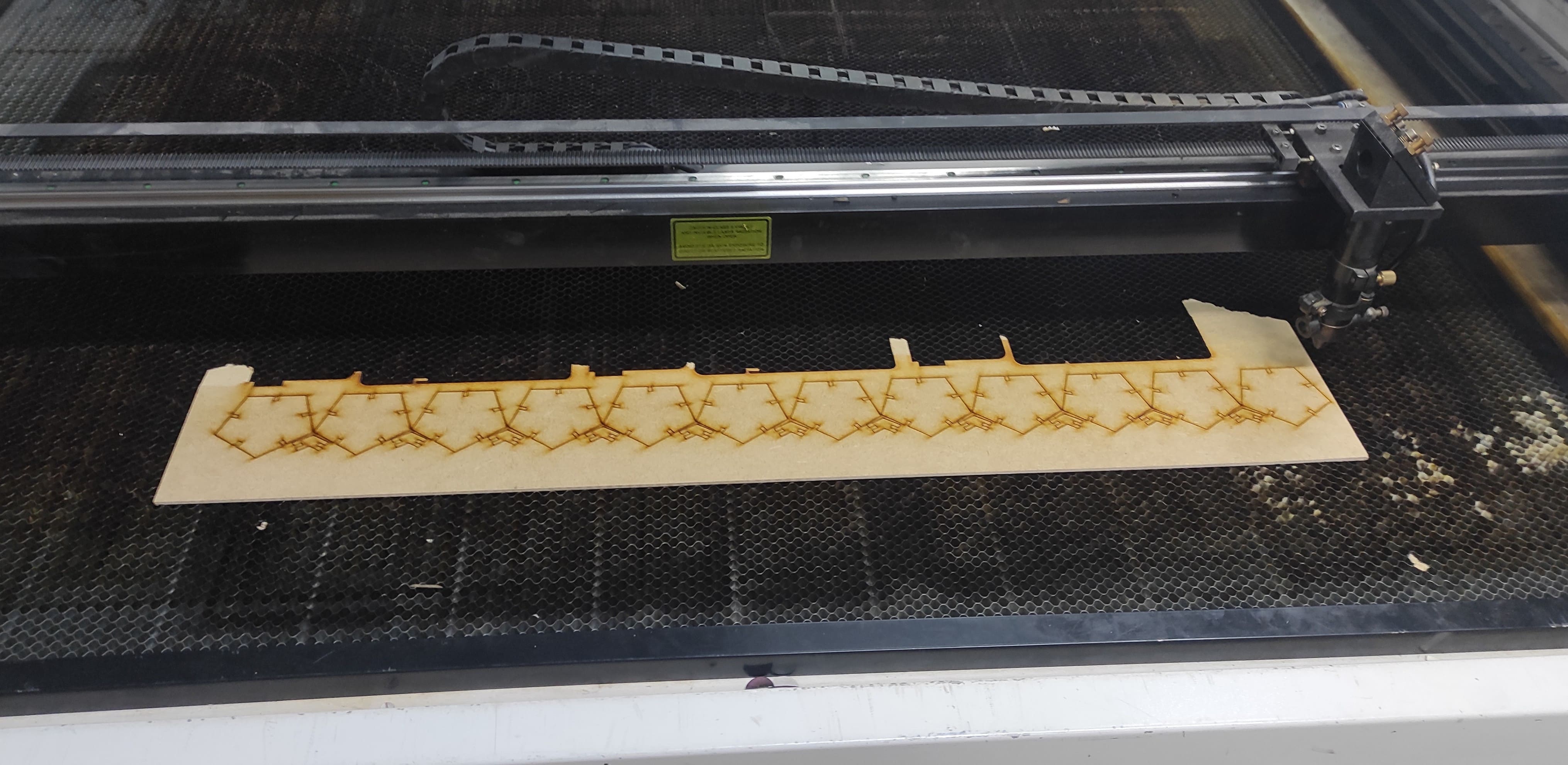
Now, we need to design our joint test. I used Fusion to create the design for several reasons: first, it allows easy handling of text and numbering; second, it is more practical for working with parametric geometry; third, the cutter is compatible with this software; and finally, it is always beneficial to learn how to use new software.
After that, I placed the text in RDWorks. I used two colors: red for cutting (50% power and 20 mm/s speed) and blue for rastering (20% power and 100 mm/s speed).

Next, we cut the piece using the laser machine and evaluated the results.
Joint inspection shows that a 3 mm measurement results in a loose fit, while a 2.835 mm measurement fits precisely.
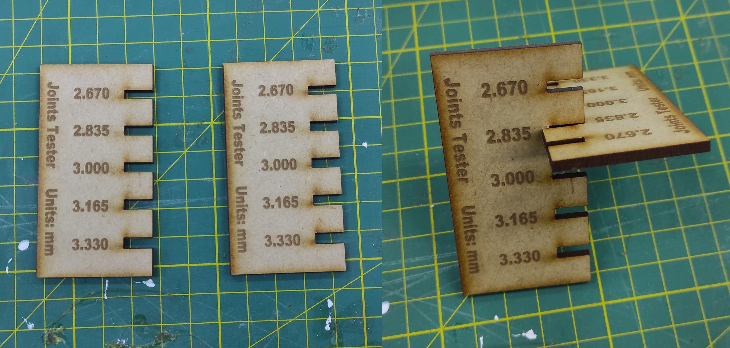
The 2.835 mm measurement will be essential for future manufacturing, ensuring precise joint fit in the final project components.
Individual Assignment
Parametric press-fit construction kit
6. Parametric Design in Practice
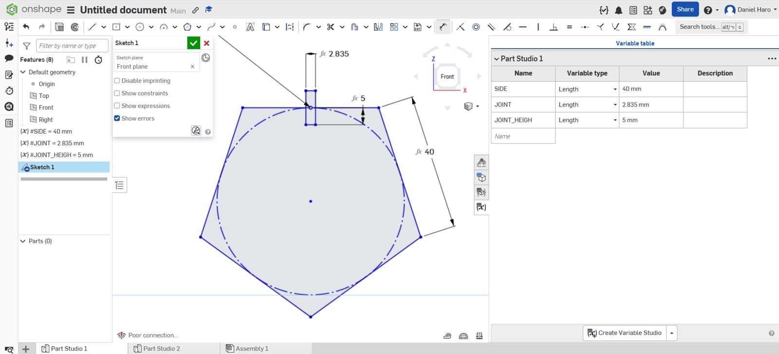
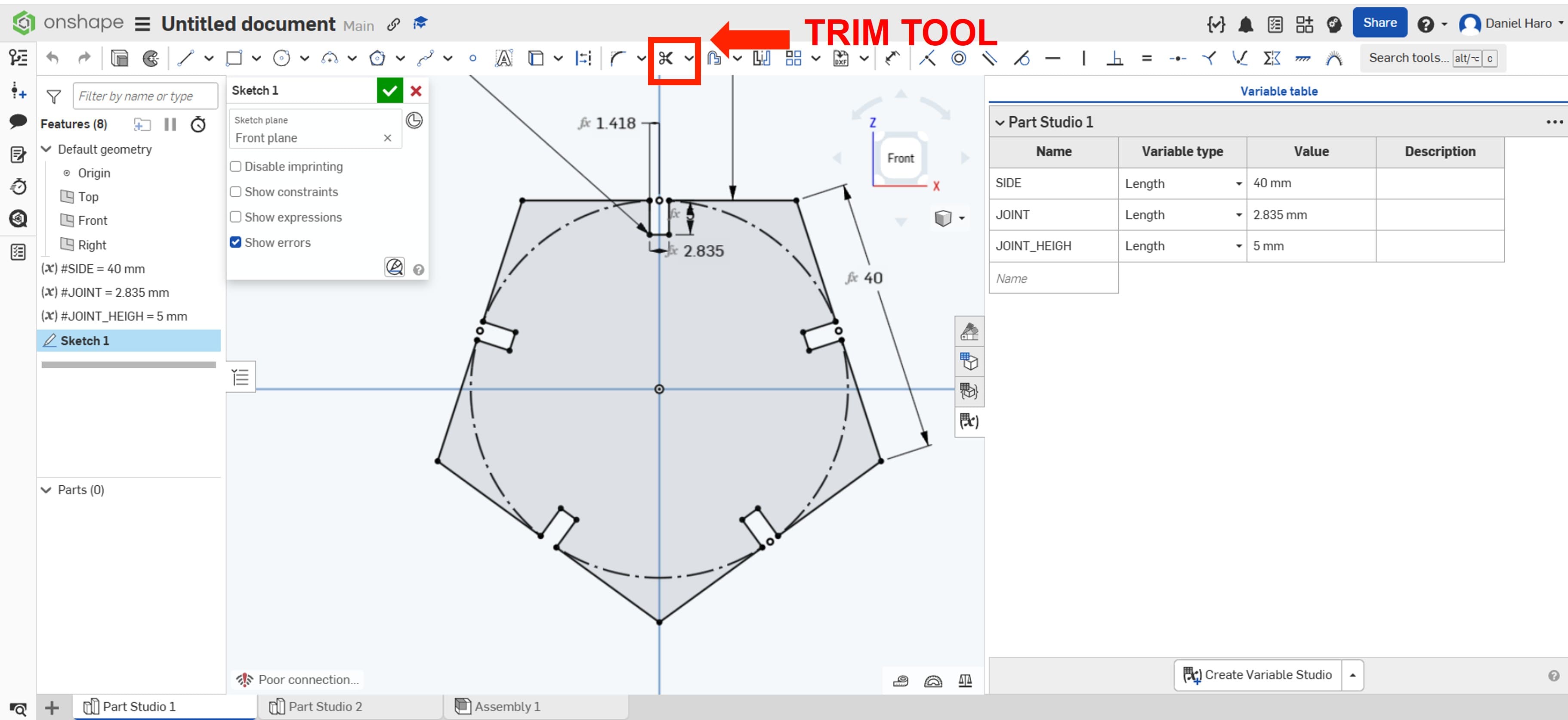
I used Onshape to develop the parametric design of the dodecagon, beginning with the definition of key parameters and design constraints.
I began by drawing a five-sided polygon and defining the variables for the design parameters, allowing each parameter to be adjusted to see its impact on the design.
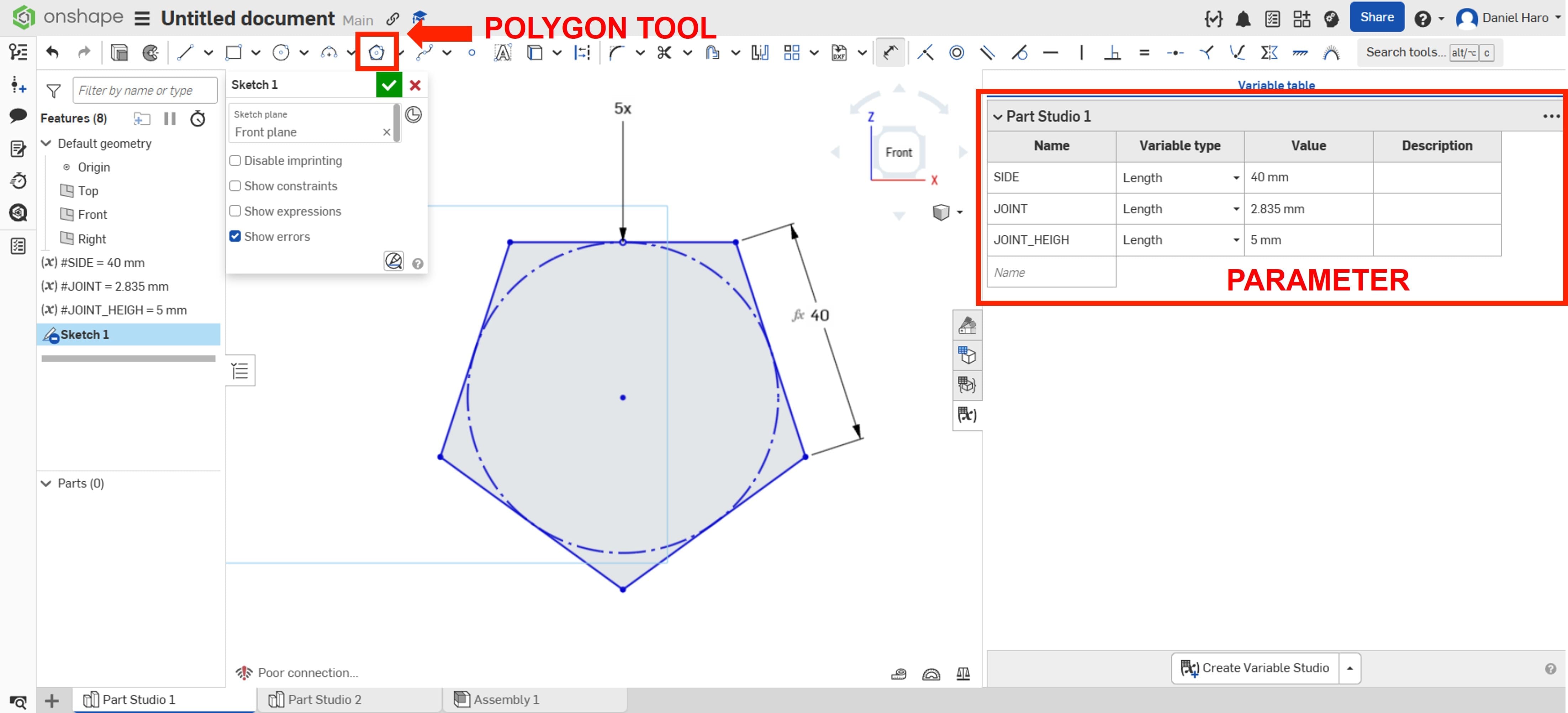
After that, I used the rectangle tool to create the joint, setting the joint variable to a value of 2.835 mm.
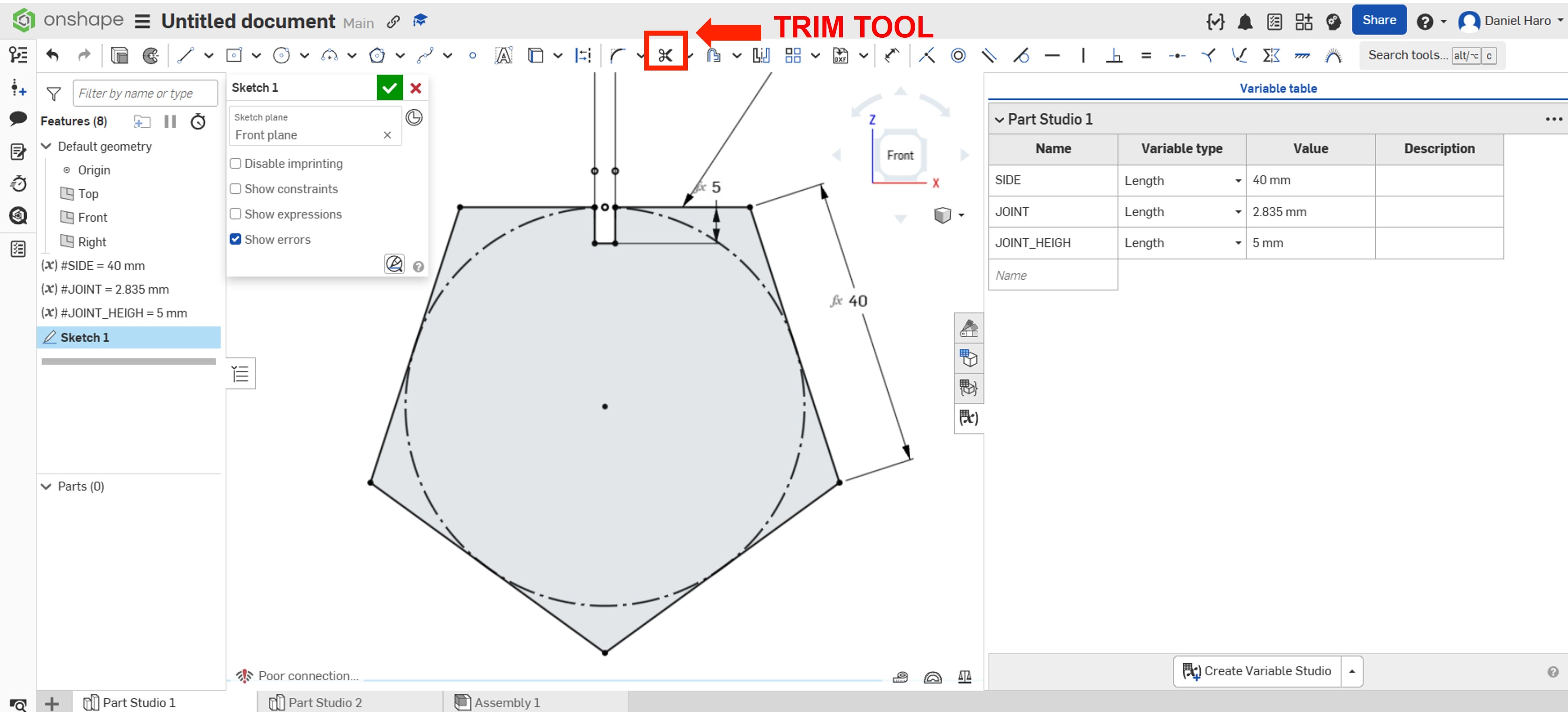
Then, I used the Trim tool to cut away the lines that were not required for the sketch.
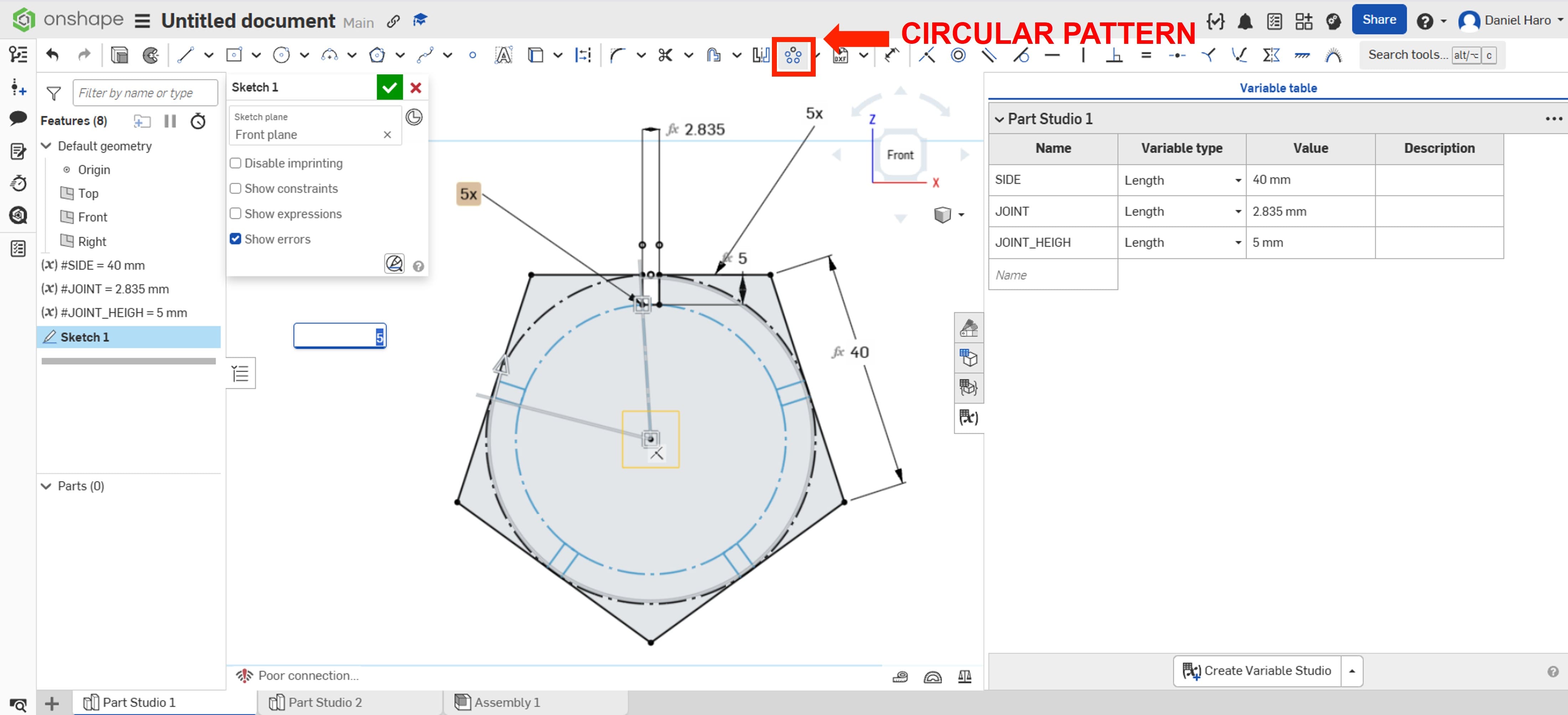
After that, I used the circular pattern to duplicate the design, so I didn’t need to create each element one by one.
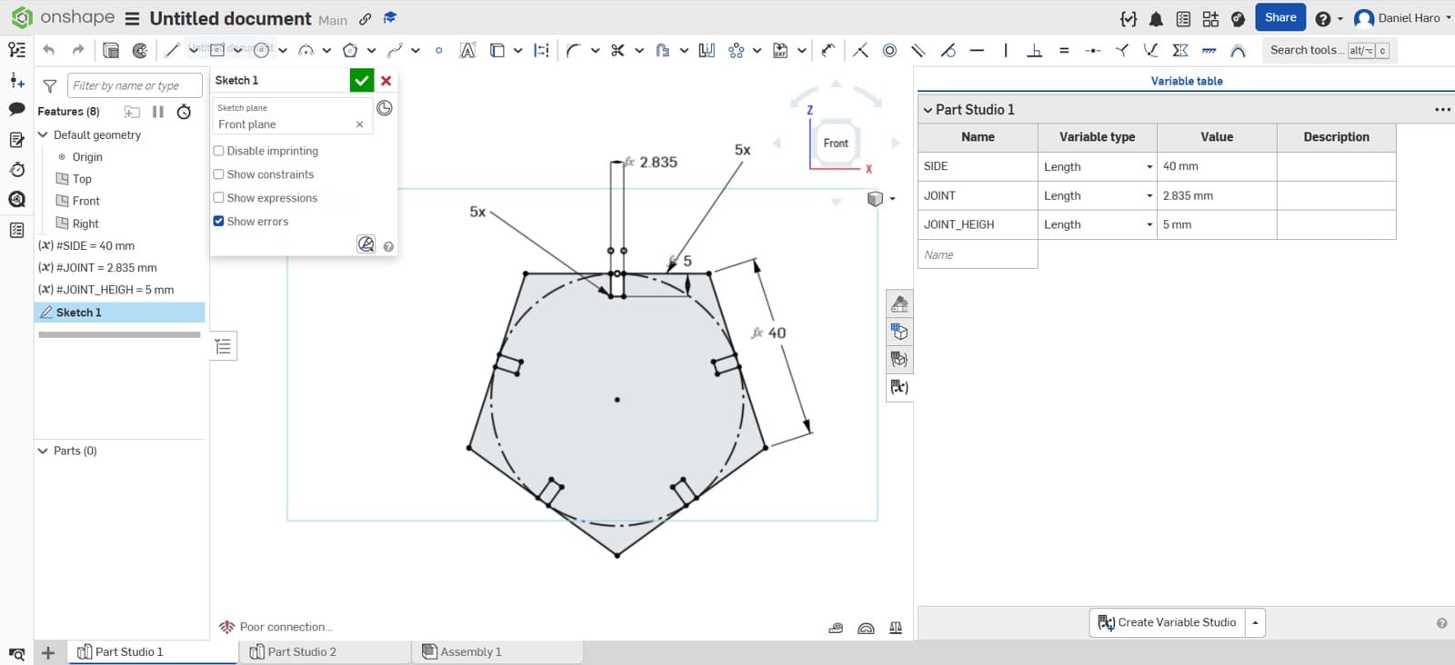
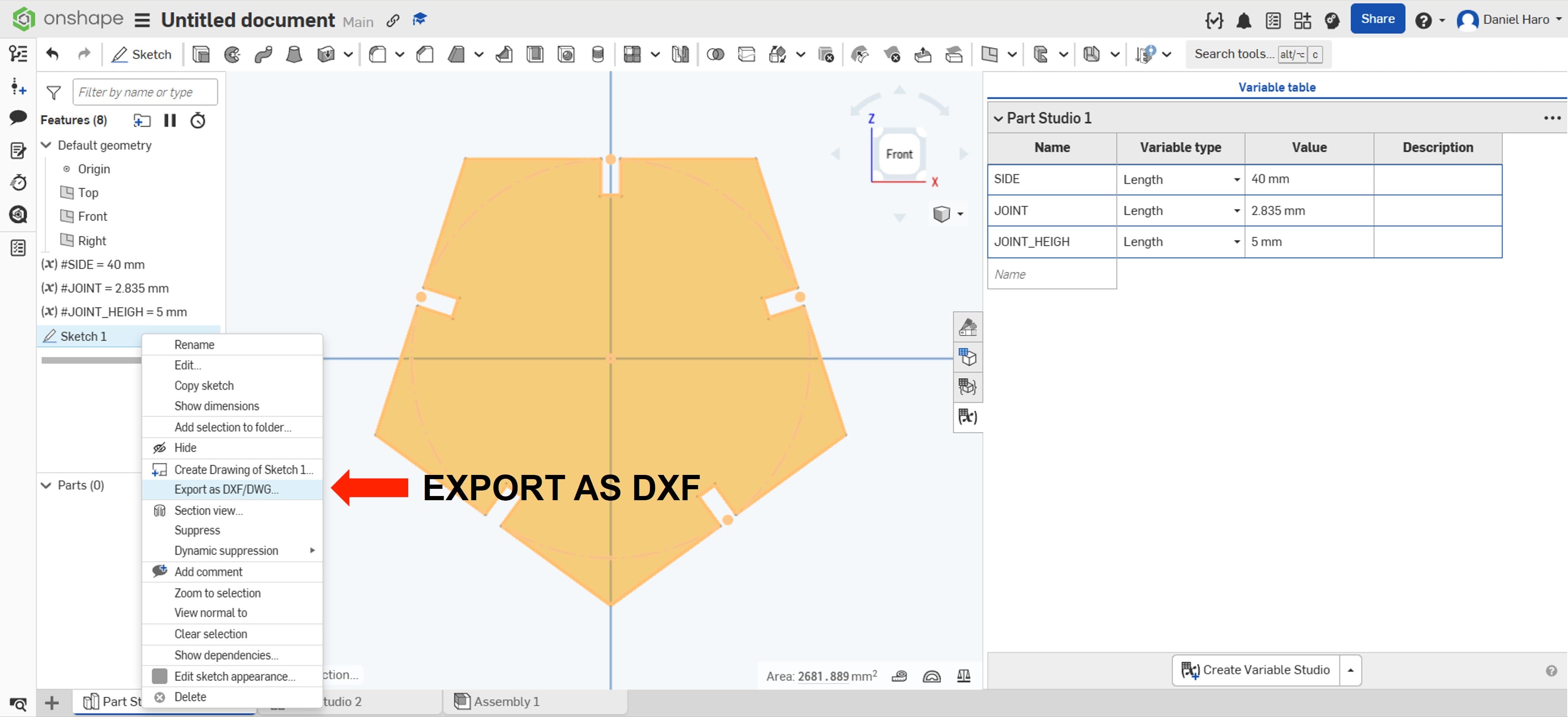
Finally, I used the Trim tool to refine the design and make it ready for manufacturing.
I exported the sketch to DXF for cutting on the laser cutting machine.
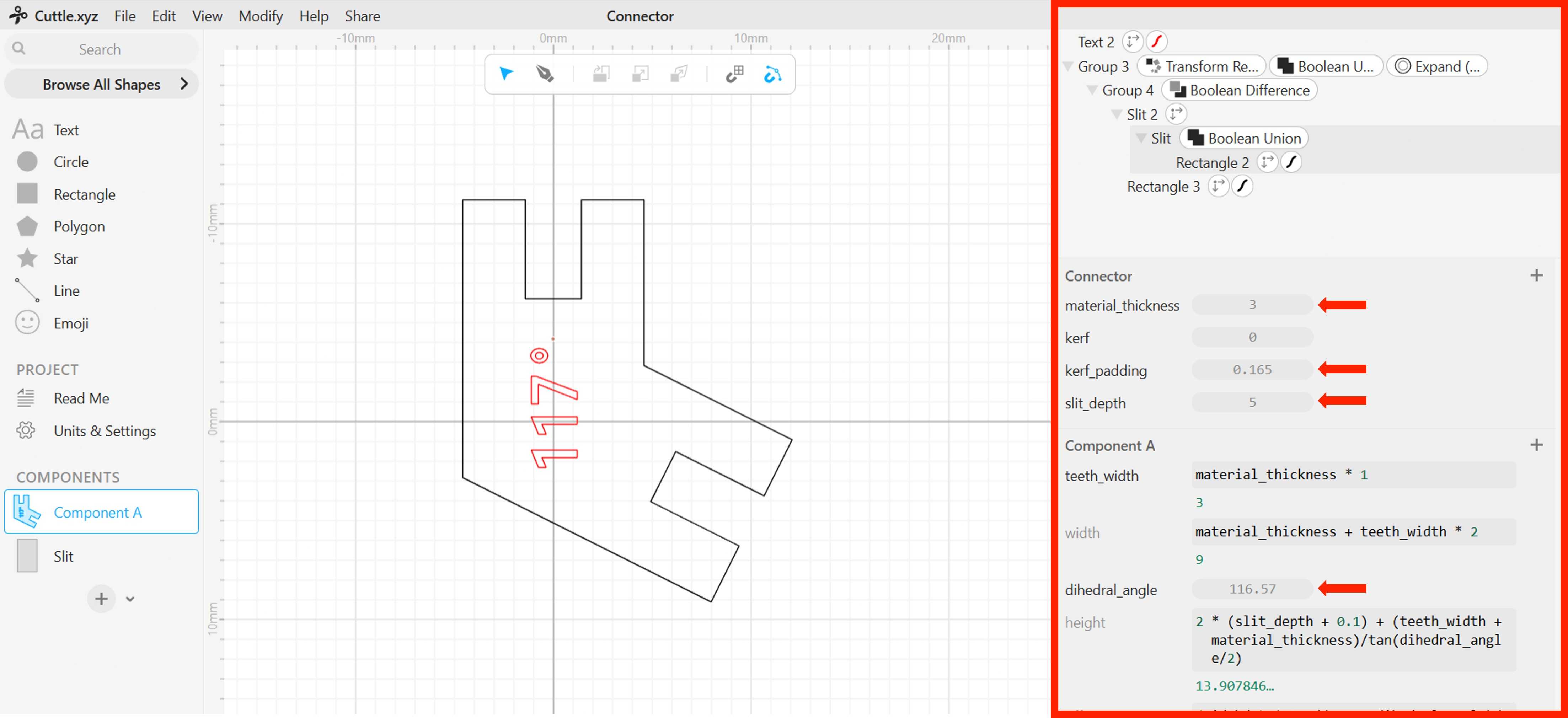
For the connector, I used the excellent design developed on another Fab Academy page by Alberto Torres. He created the connector using Cuttle, allowing it to be fully parametric. I reused his design and adjusted the parameters to fit my specific needs.
Fabacademy Alberto Torres: Assigment 3
Link Cuttle.xyz application: My parametric connector
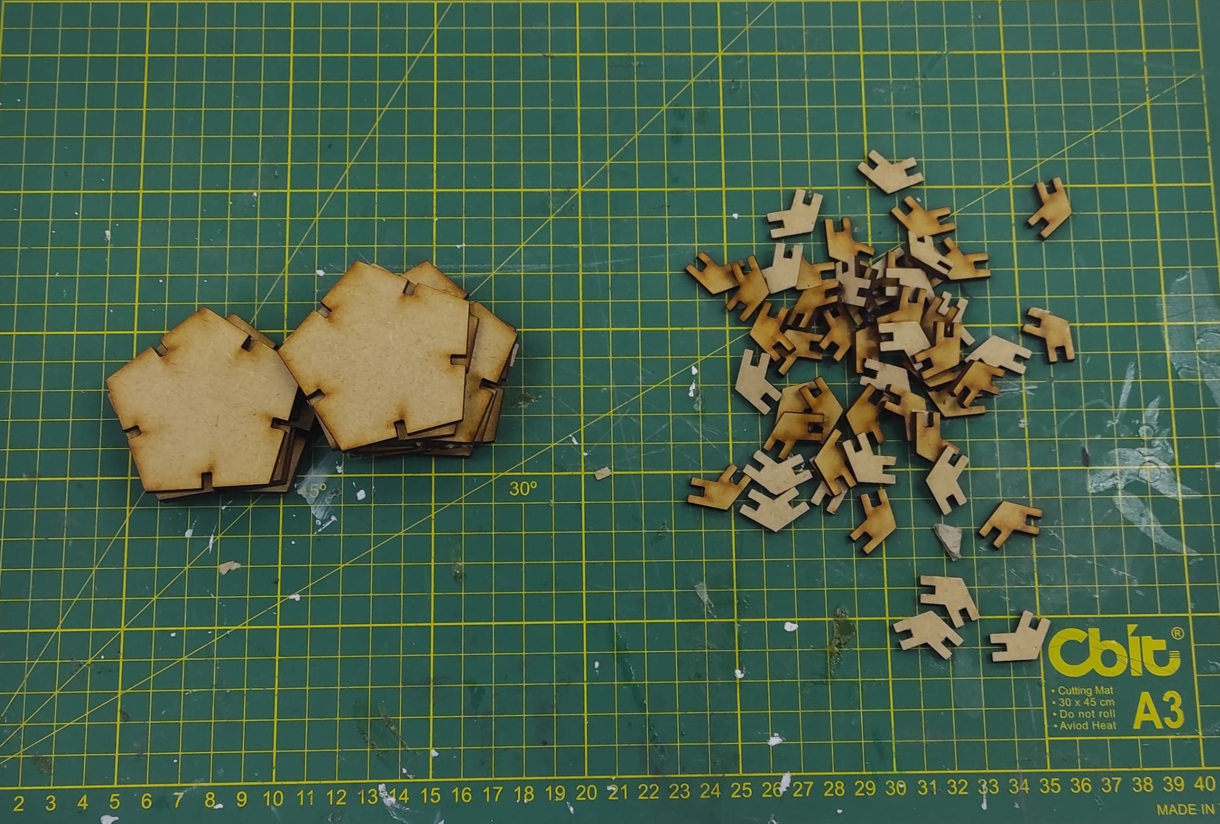
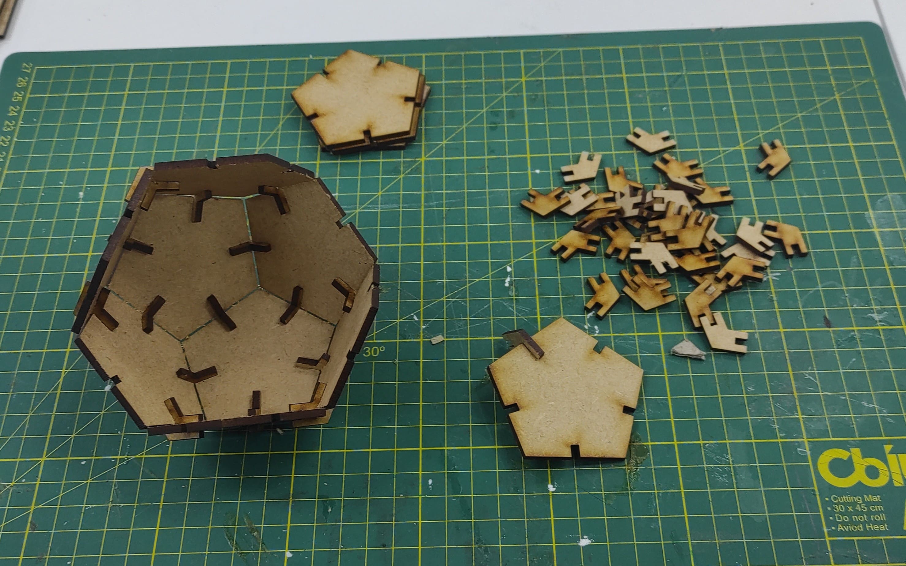
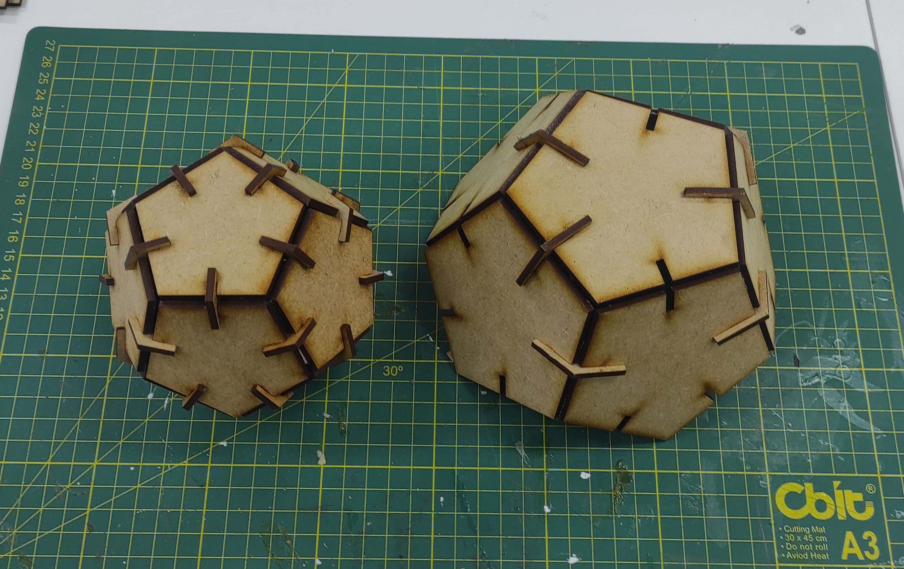
7. Laser Cutting & Assembly
With all the DXF files ready, I prepared the laser cutting machine and began cutting the components. Once again, I used RDWorks to set the laser cutting parameters, with the power set to 50% and the cutting speed set to 20 mm/s.
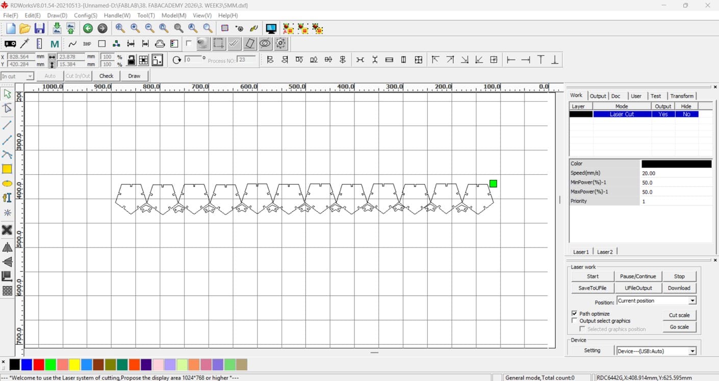
The laser cutting process was successful, and all components were cut precisely.
I collected all the MDF components and started planning the assembly process.
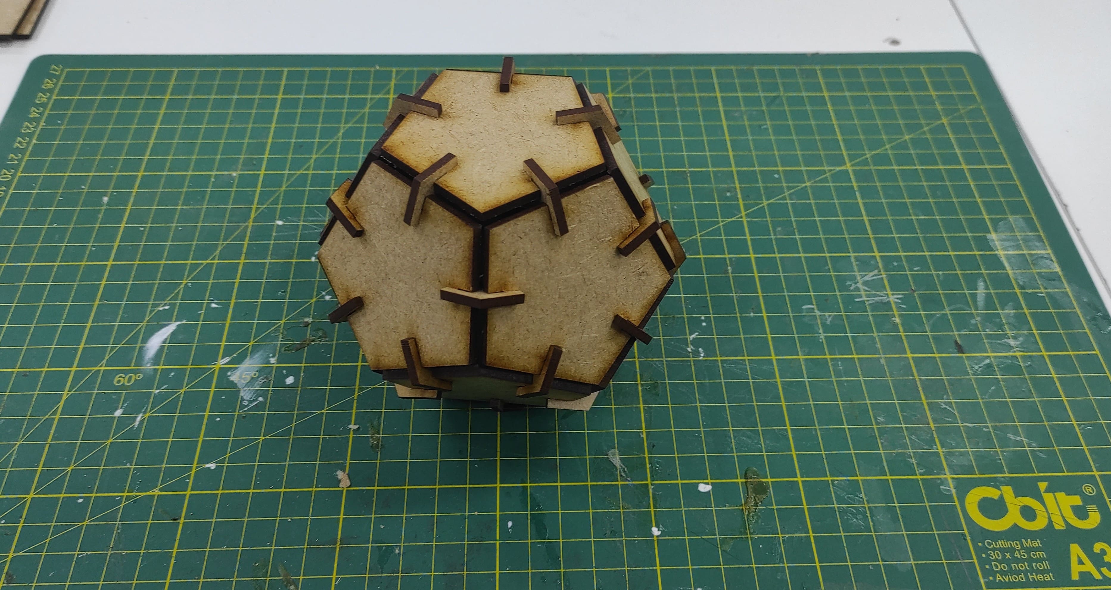
After understanding the correct assembly sequence, I started assembling the components one by one. As the assembly progressed, the model gradually took shape and aligned well with the original design.
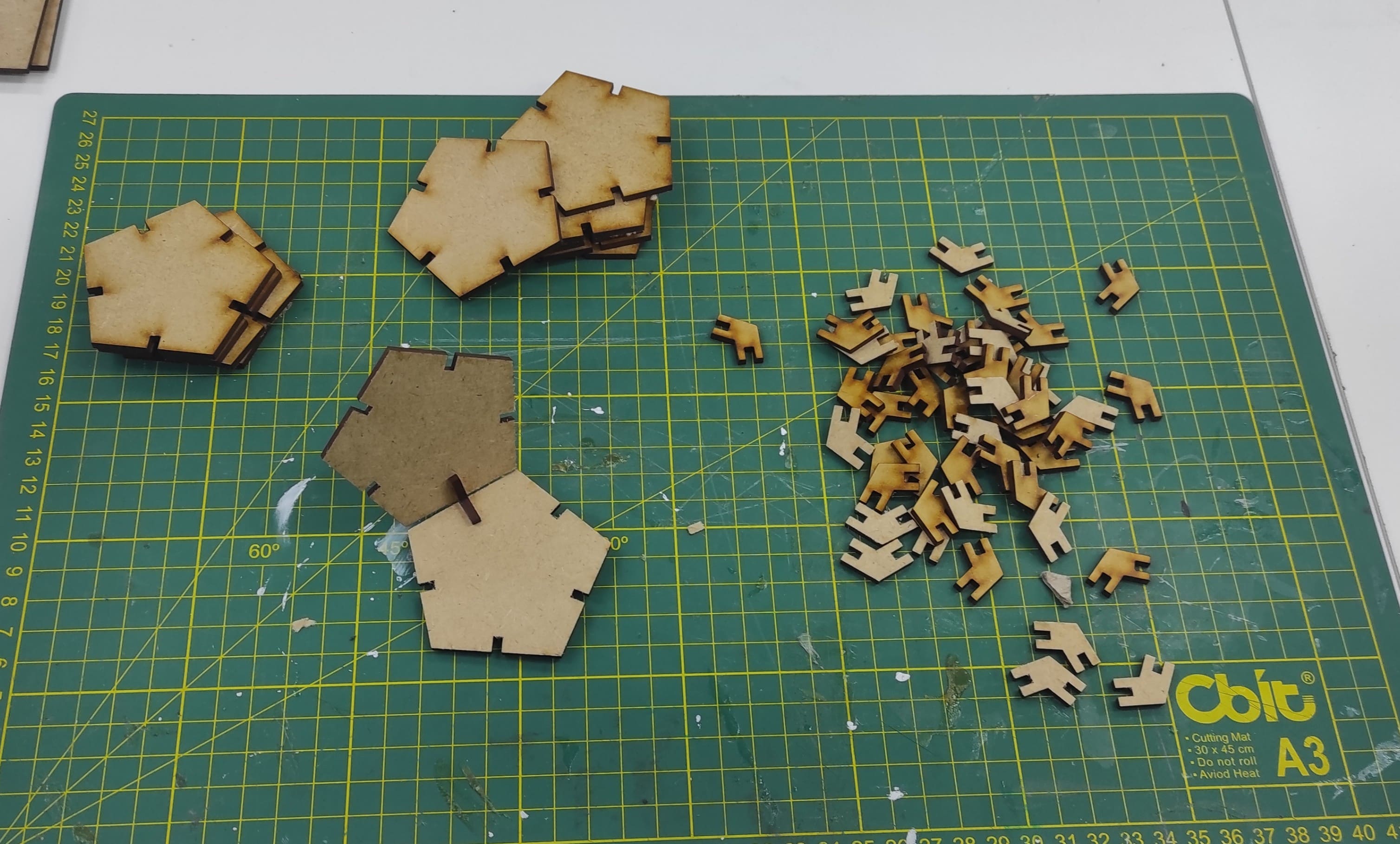
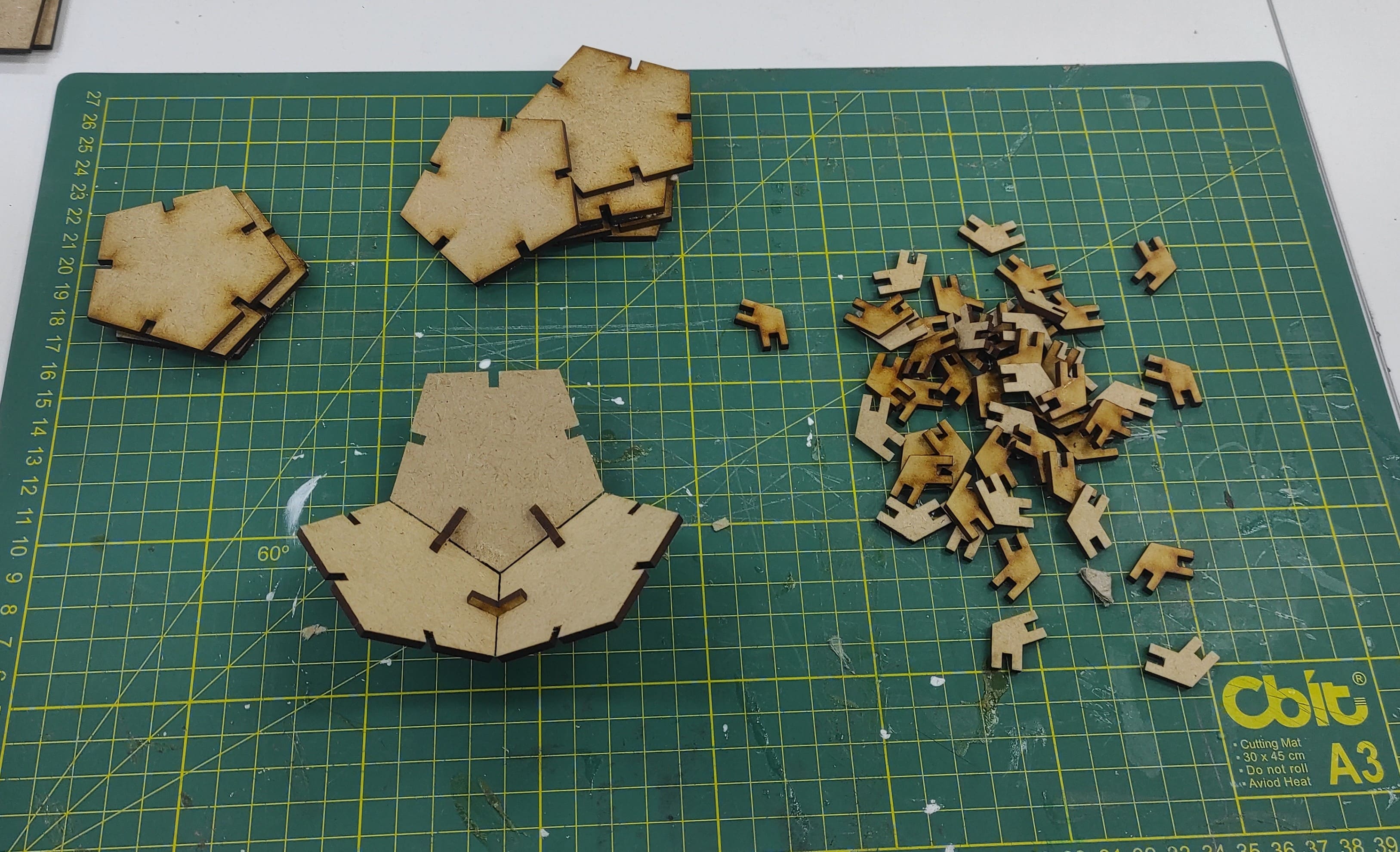
Finally, I completed the assembly, and the model was ready for use. The body was compact, rigid, and well-structured.
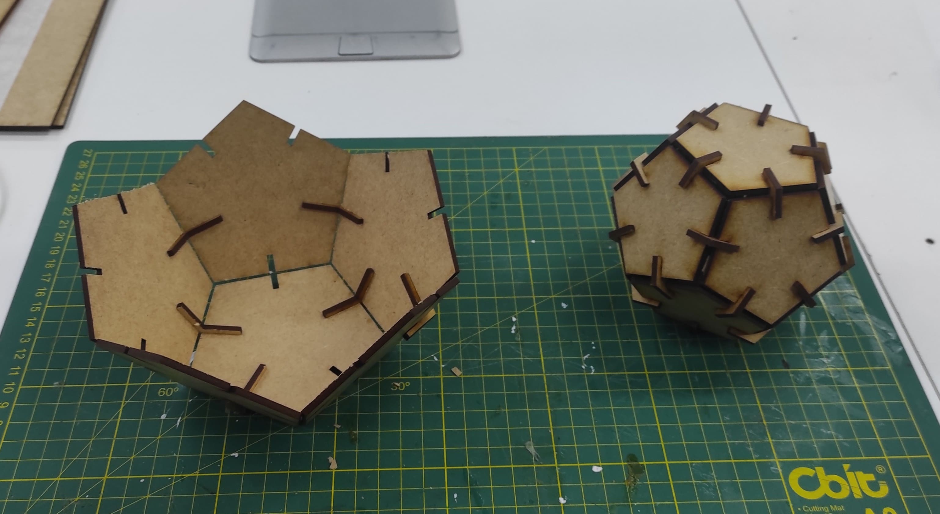
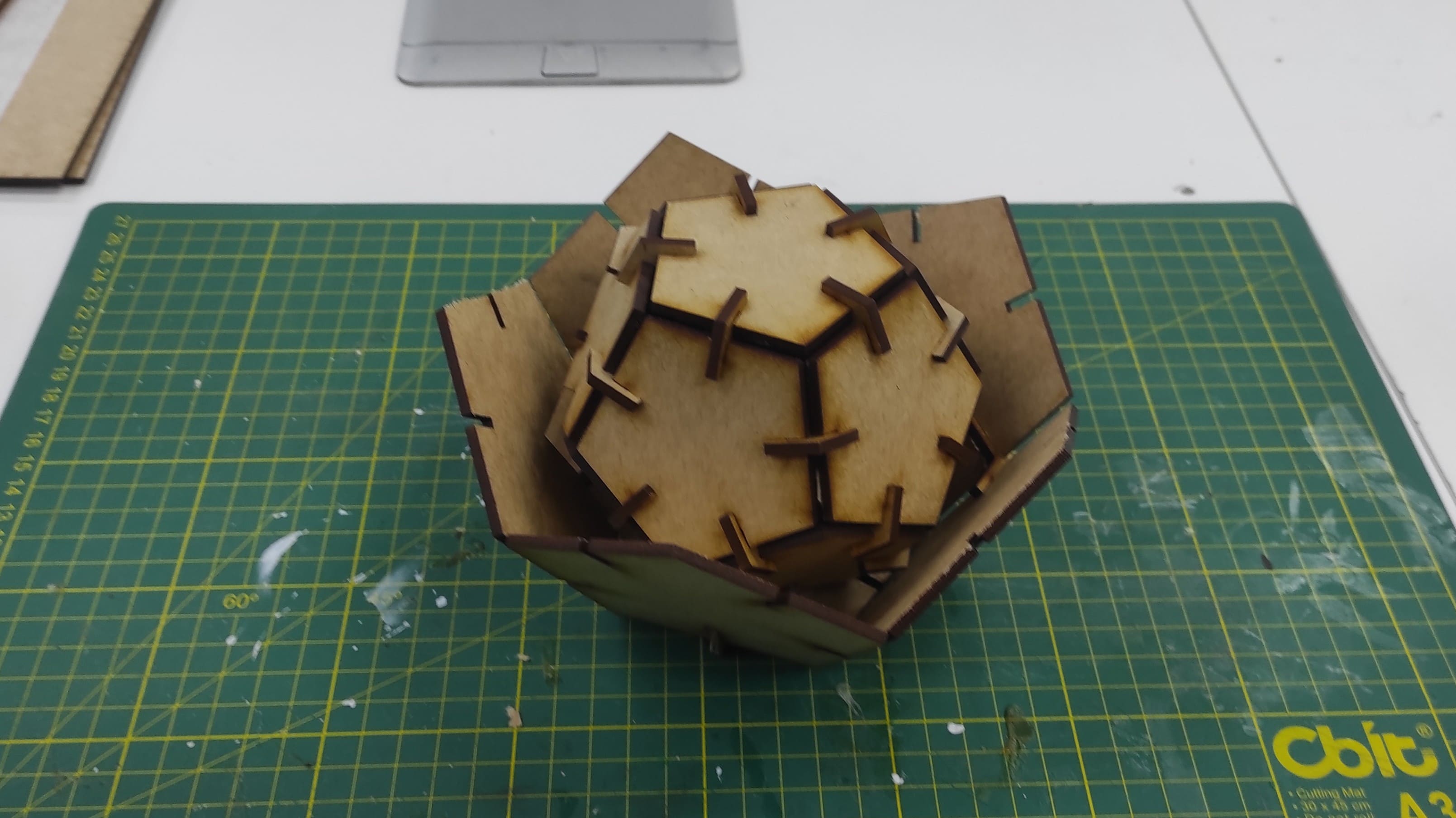
I produced another version by modifying the existing parameters, which eliminated the need to create a new sketch from the beginning.
Vinyl cutter
A vinyl cutter is a machine used to cut designs, text, or patterns from thin materials like vinyl or heat-transfer film. It’s commonly used for making stickers, decals, signage, and custom graphics.
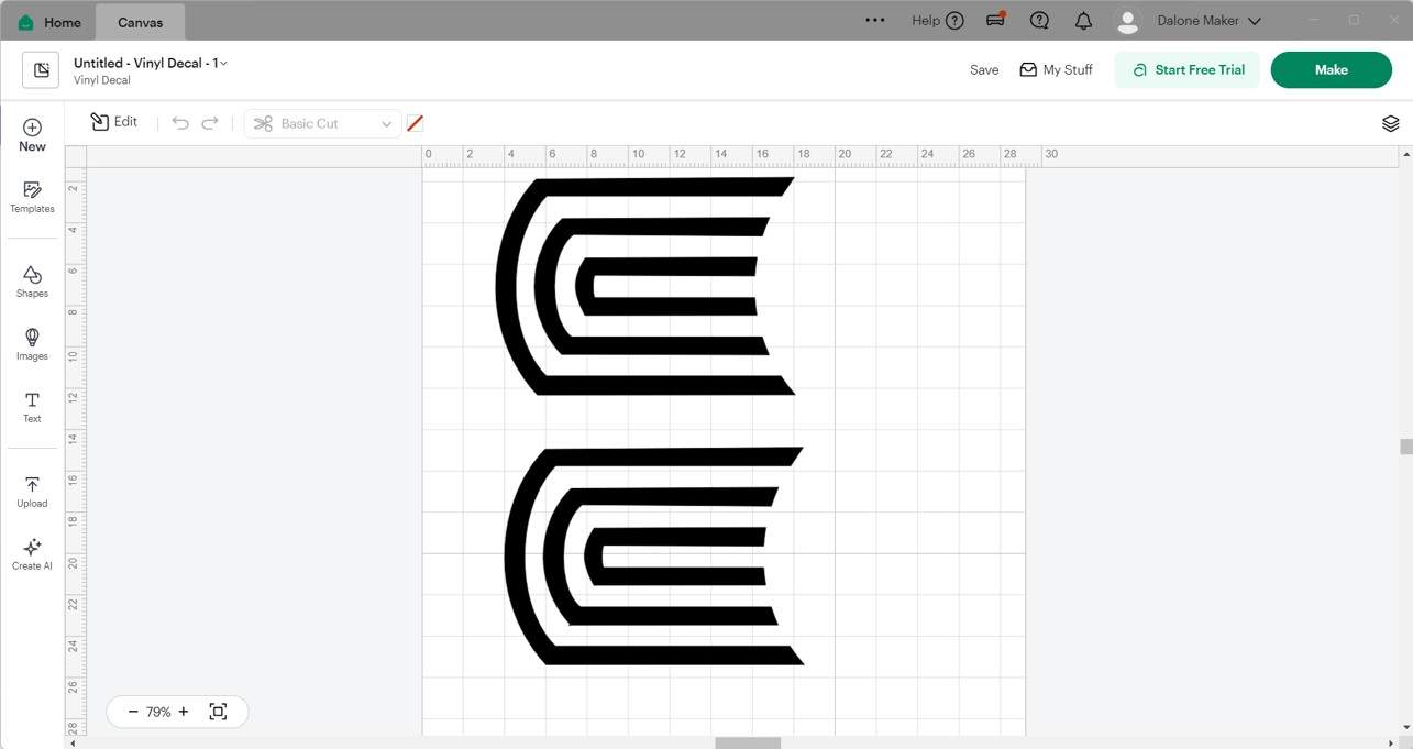
I decided to work with my university’s logo, and luckily I already had the DXF files, as we use them frequently.
I used the Cricut software and uploaded the design file.
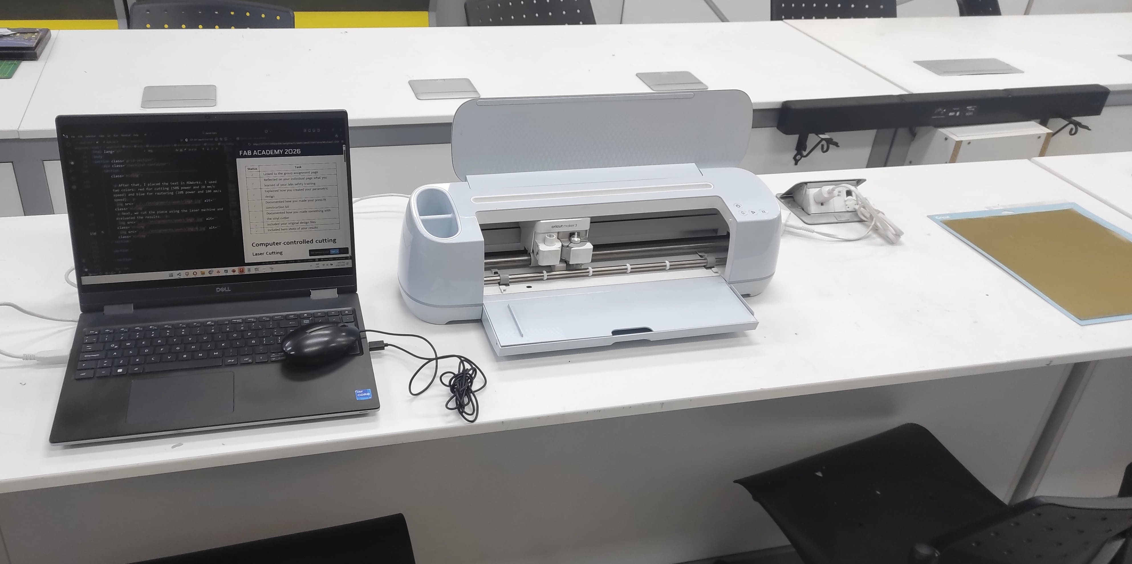
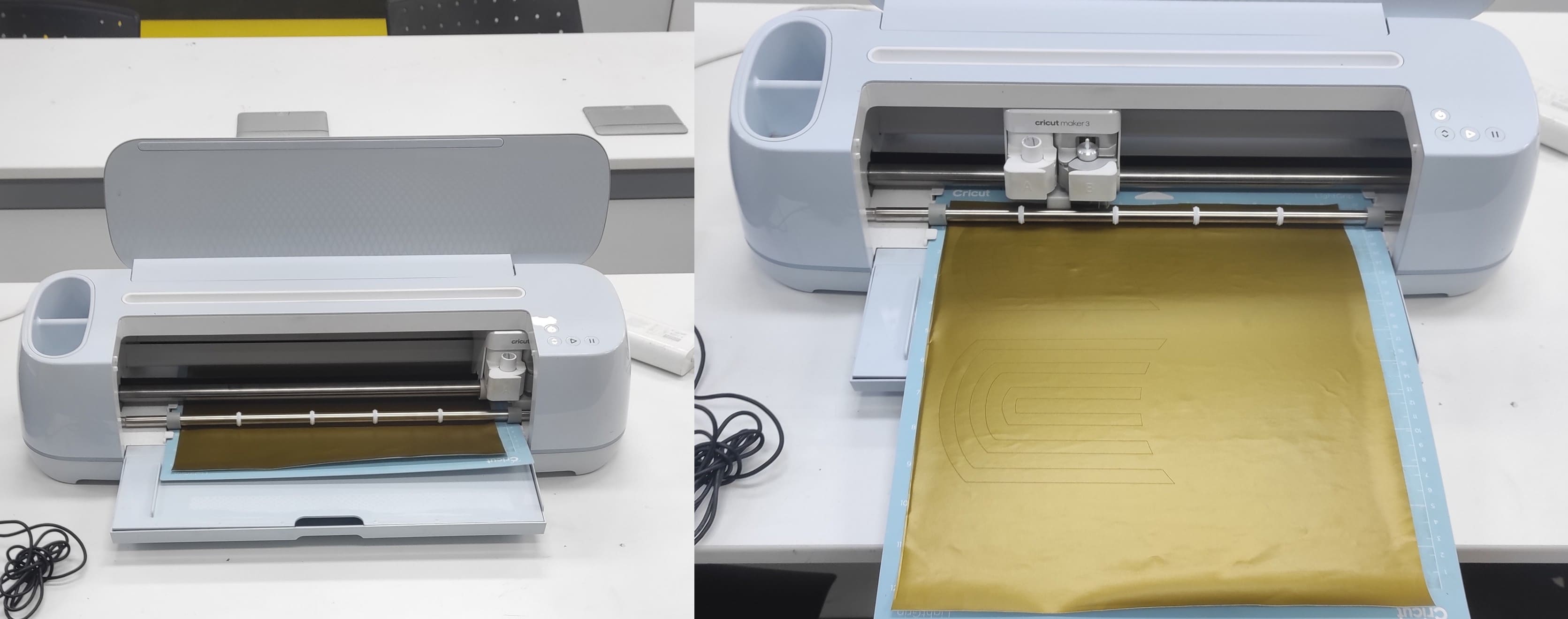
I prepared the Cricut Maker 3 with all required connections and materials.
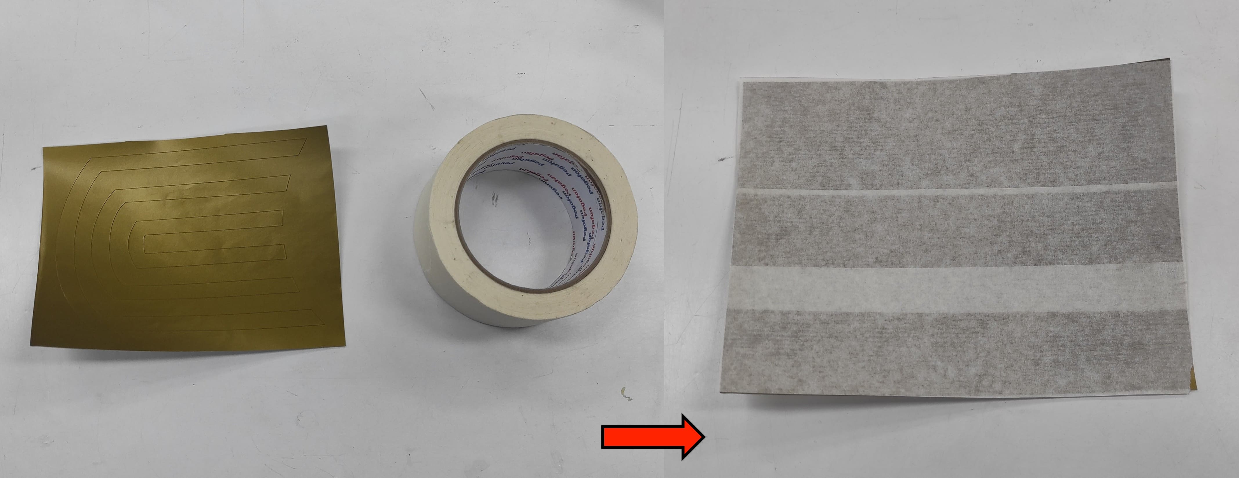
I used gold vinyl material to enhance the appearance of the final design.
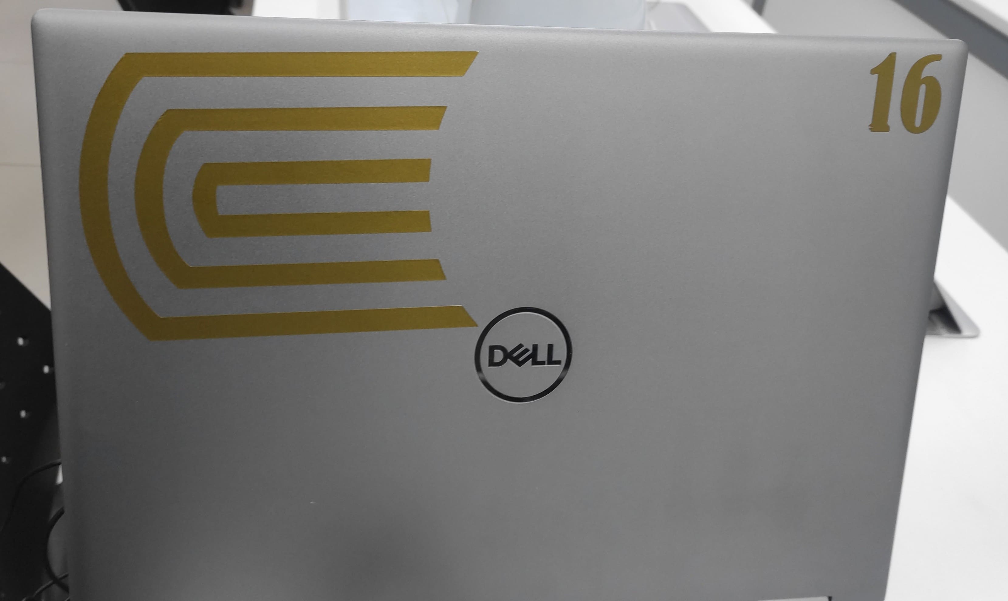
Once the machine was set up, it started cutting and the design was successfully completed.
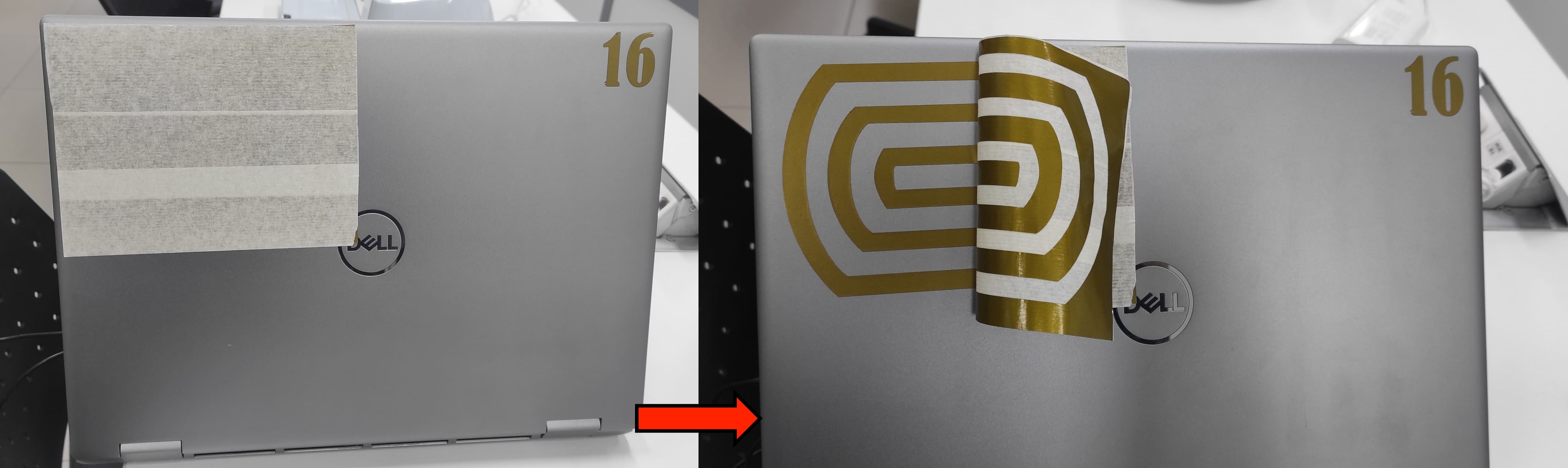
I used masking tape to hold the vinyl in place and maintain the correct position of the cut design.
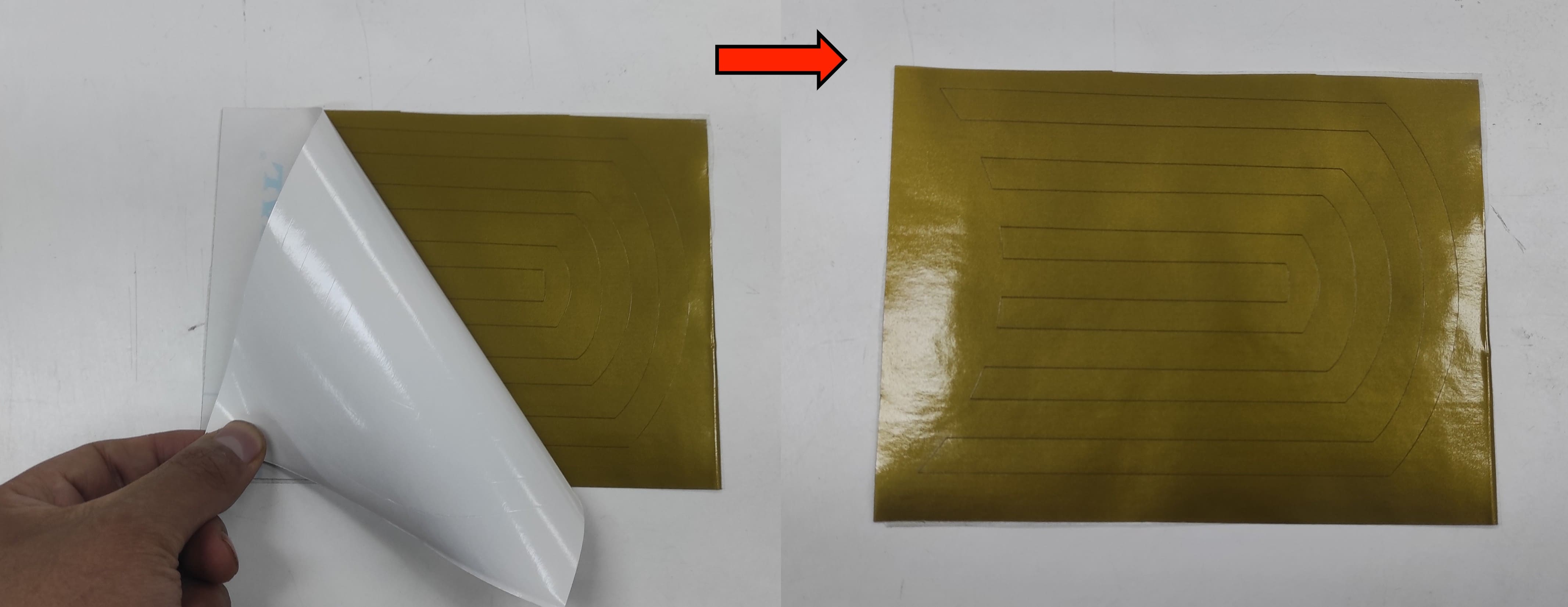
After that, I removed the backing from the vinyl adhesive, making it ready to be applied to a surface.
I chose to place it on my laptop so it would be visible and serve as a reference for others.
8. Files
Here are the files available for download.