Week 12 Progress Checklist
| Status | Task |
|---|---|
| ✓ | Documented the machine building process to the group page |
| ✓ | Documented your individual contribution to this project on your own website |
| ✓ | Linked to the group page from your individual page as well as from group page to your individual pages |
| ✓ | Shown how your team planned, allocated tasks and executed the project (Group page) |
| ✓ | Described problems and how the team solved them (Group page) |
| ✓ | Listed possible improvements for this project (Group page) |
| ✓ | Included your design files (Group page) |
Mechanical Design, Machine Design
Group Assignment
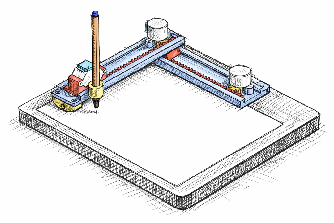
CNC Pen Plotter
For this week’s assignment, I was genuinely excited—I finally had the chance to build a CNC plotter.
The idea of turning code into motion, and motion into something visible and precise, made this project feel more than just an assignment—it felt like the beginning of something bigger.
You can see all the Project in the Group Website: FabLab UContinental
Individual Assignment
CNC Programing and Test
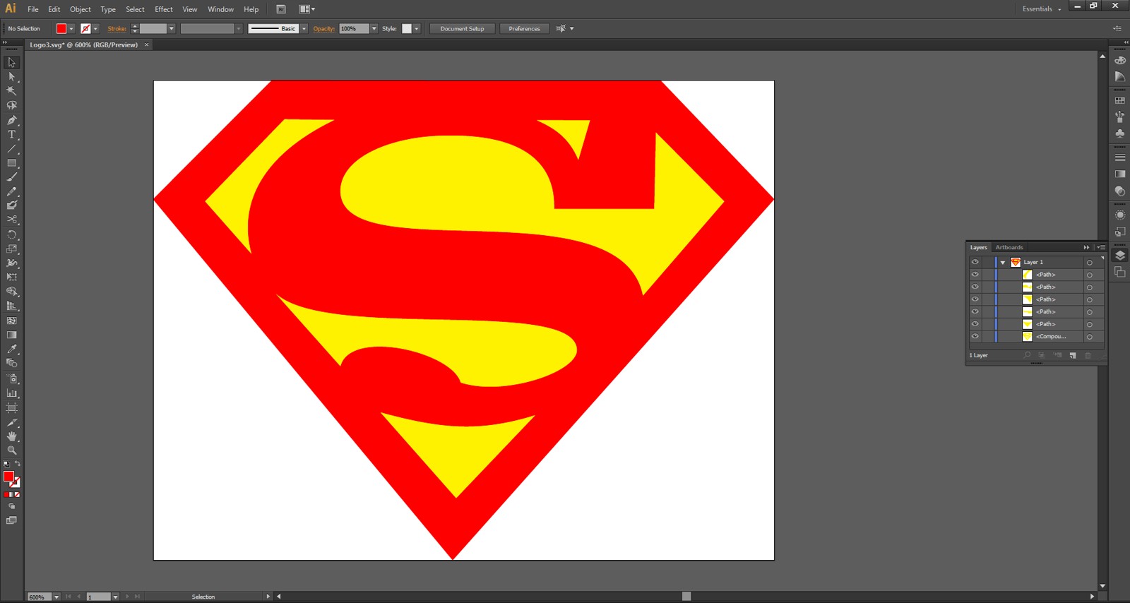
For testing our CNC pen plotter, I selected an image and exported it to SVG format using Adobe Illustrator.
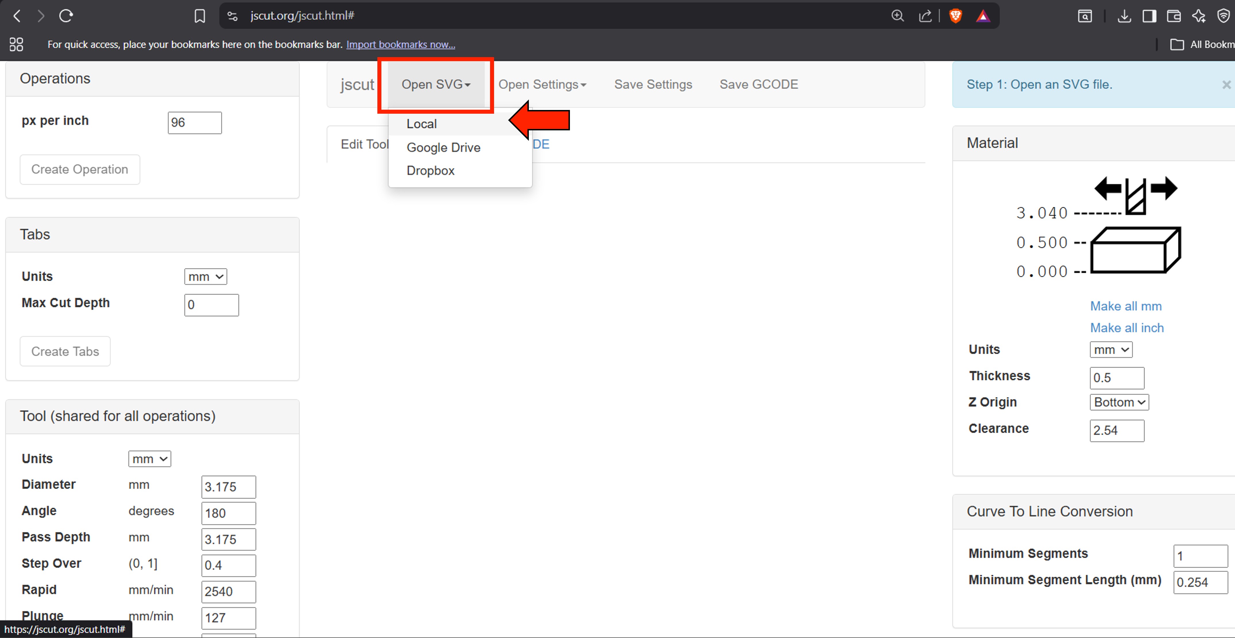
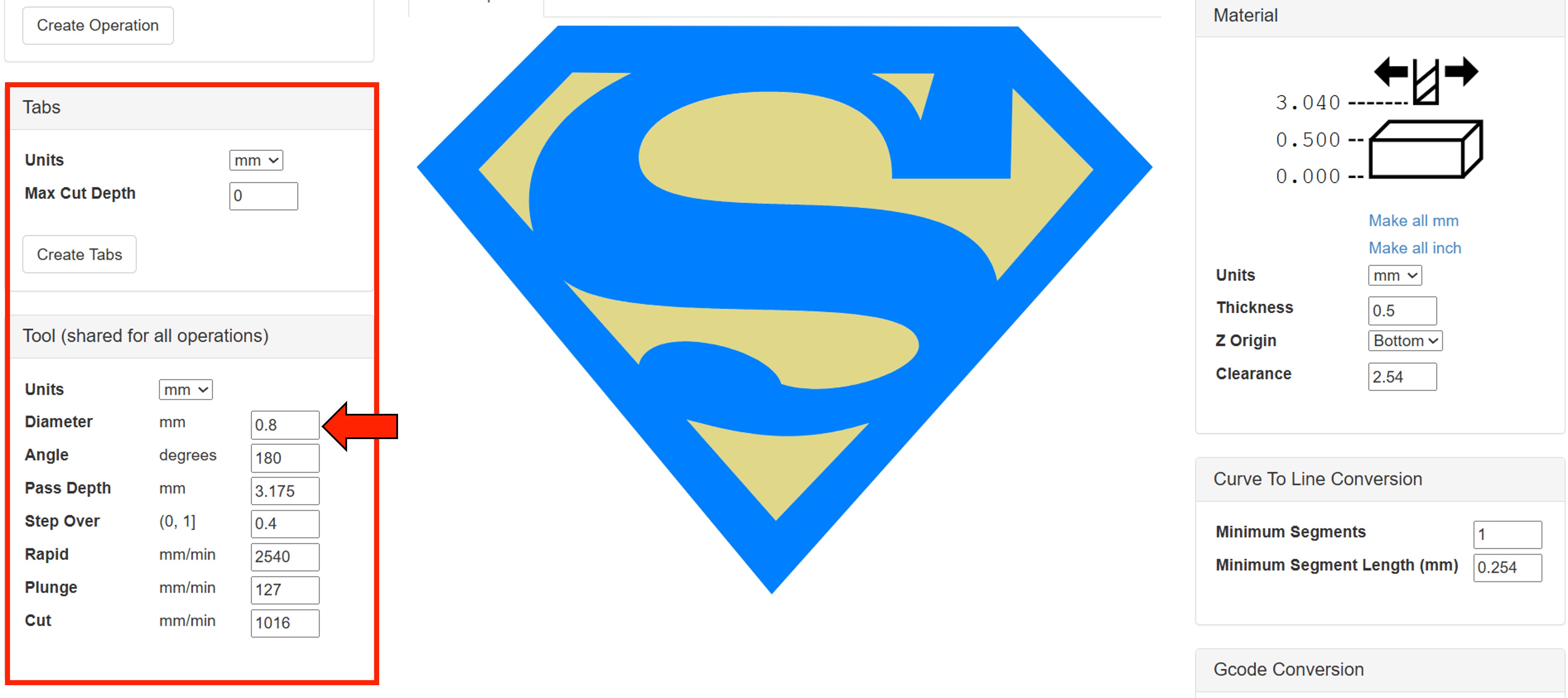
We then navigated to the JsCut website and uploaded the SVG file. In the material section, we set the parameters as shown in the image below.
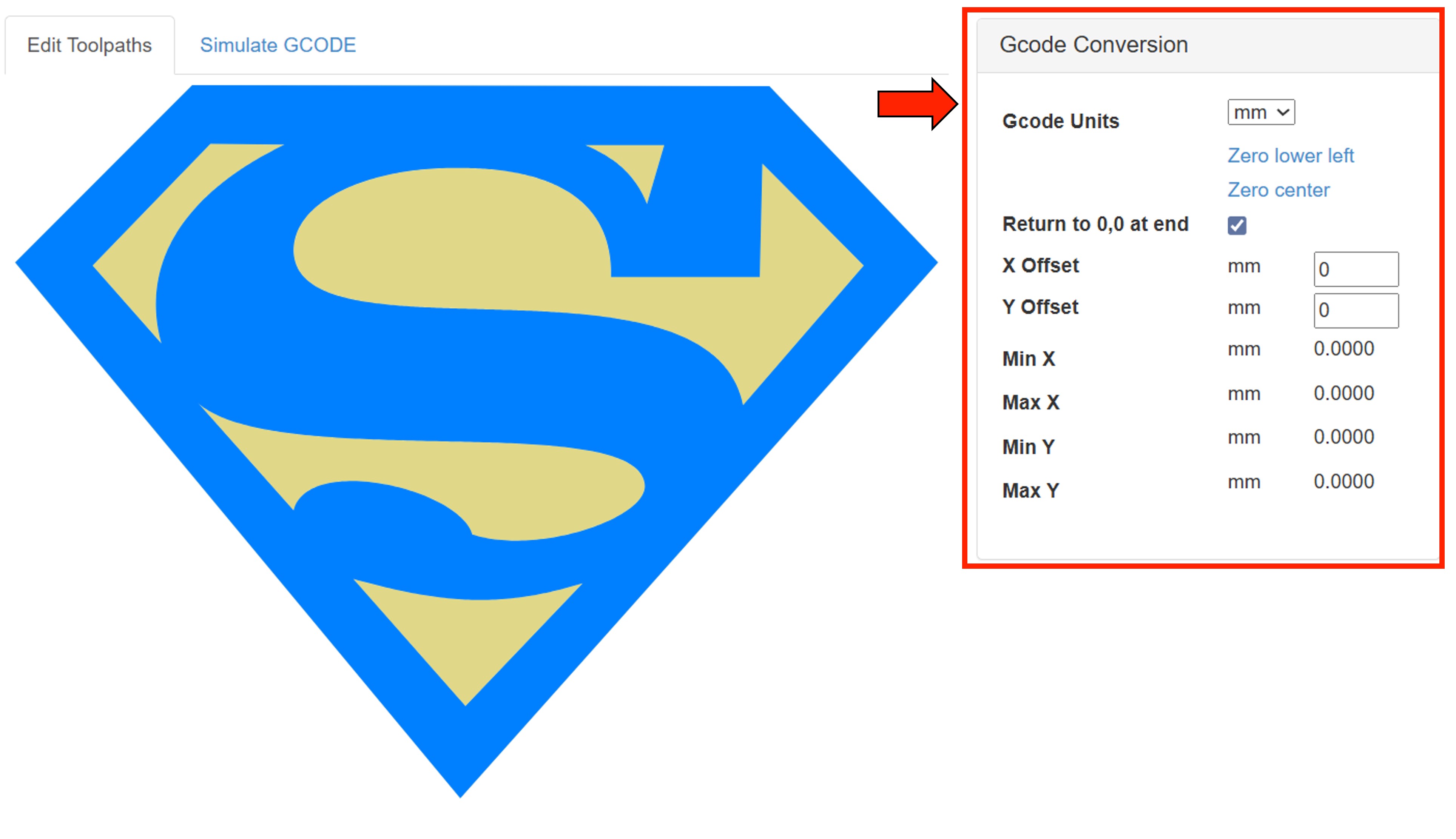
In the Gcode Conversion section, we need to active the option Return to 0,0 at end.
In the Tool section, we need to set the diameter to match the pen tip diameter.
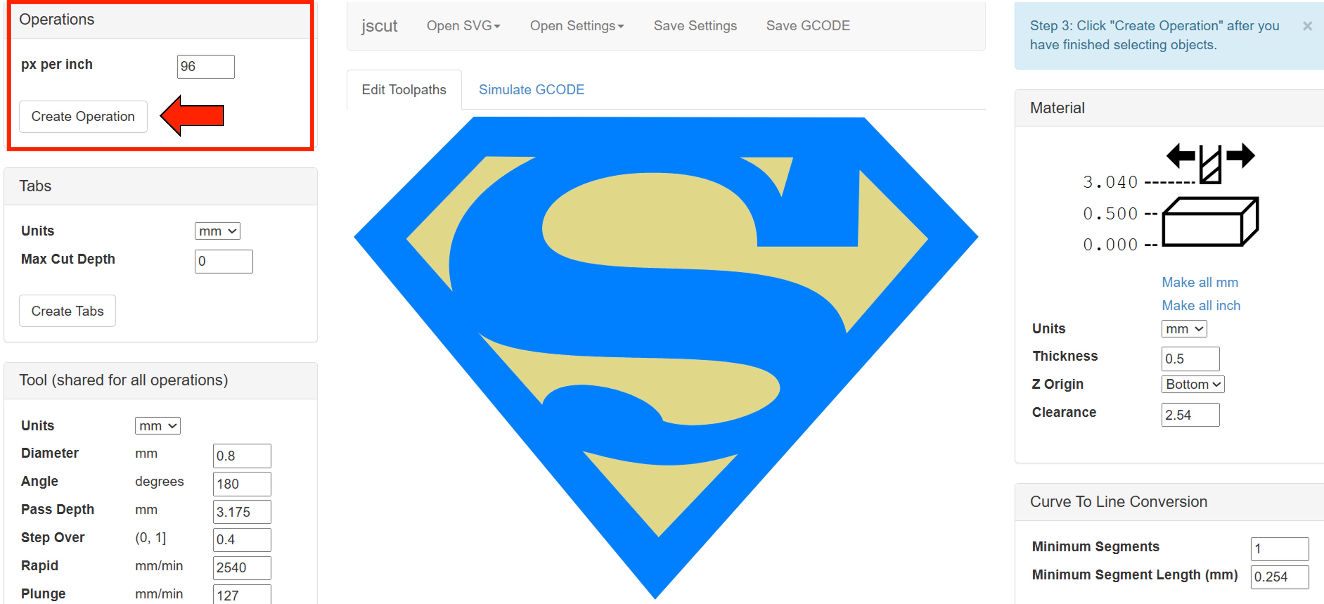
In the Operation section, click on “Create Operation.”
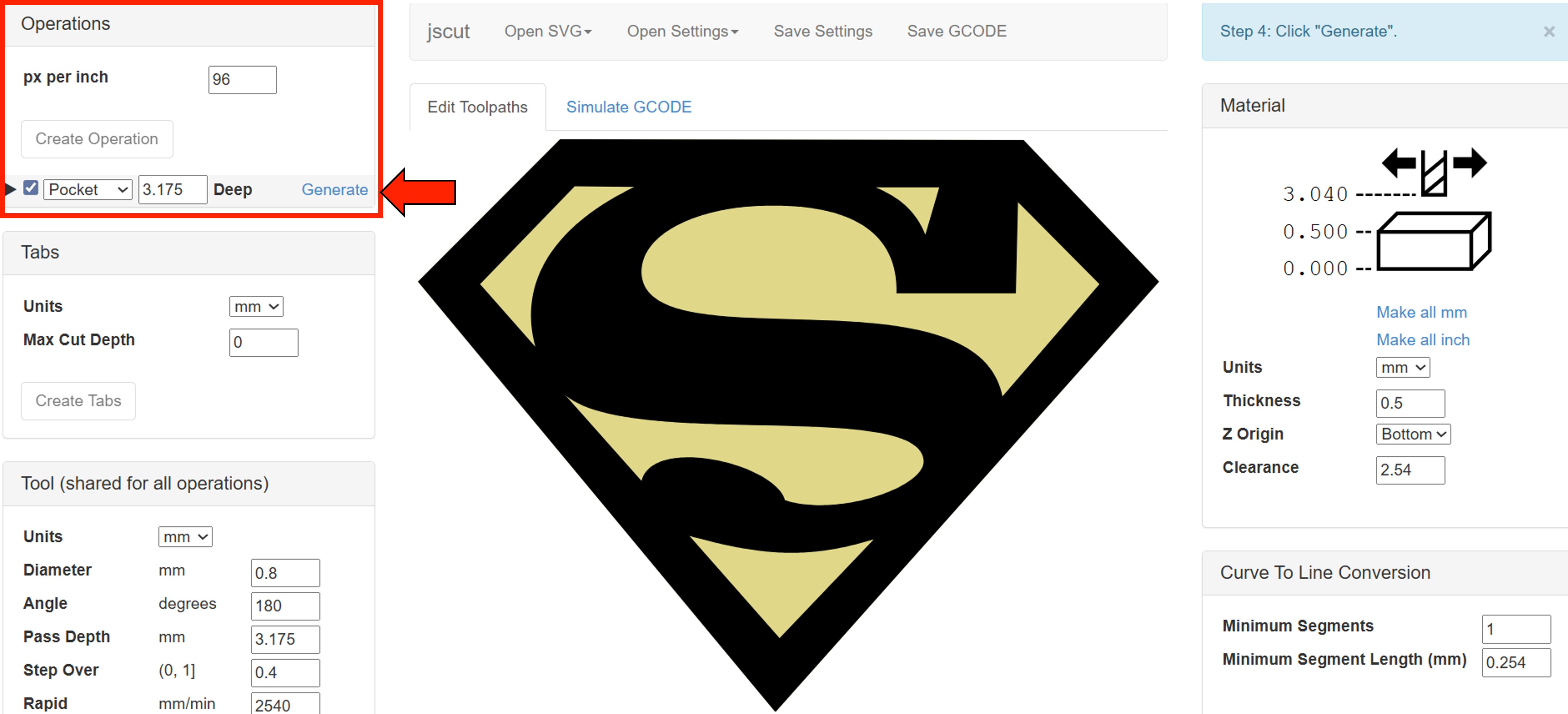
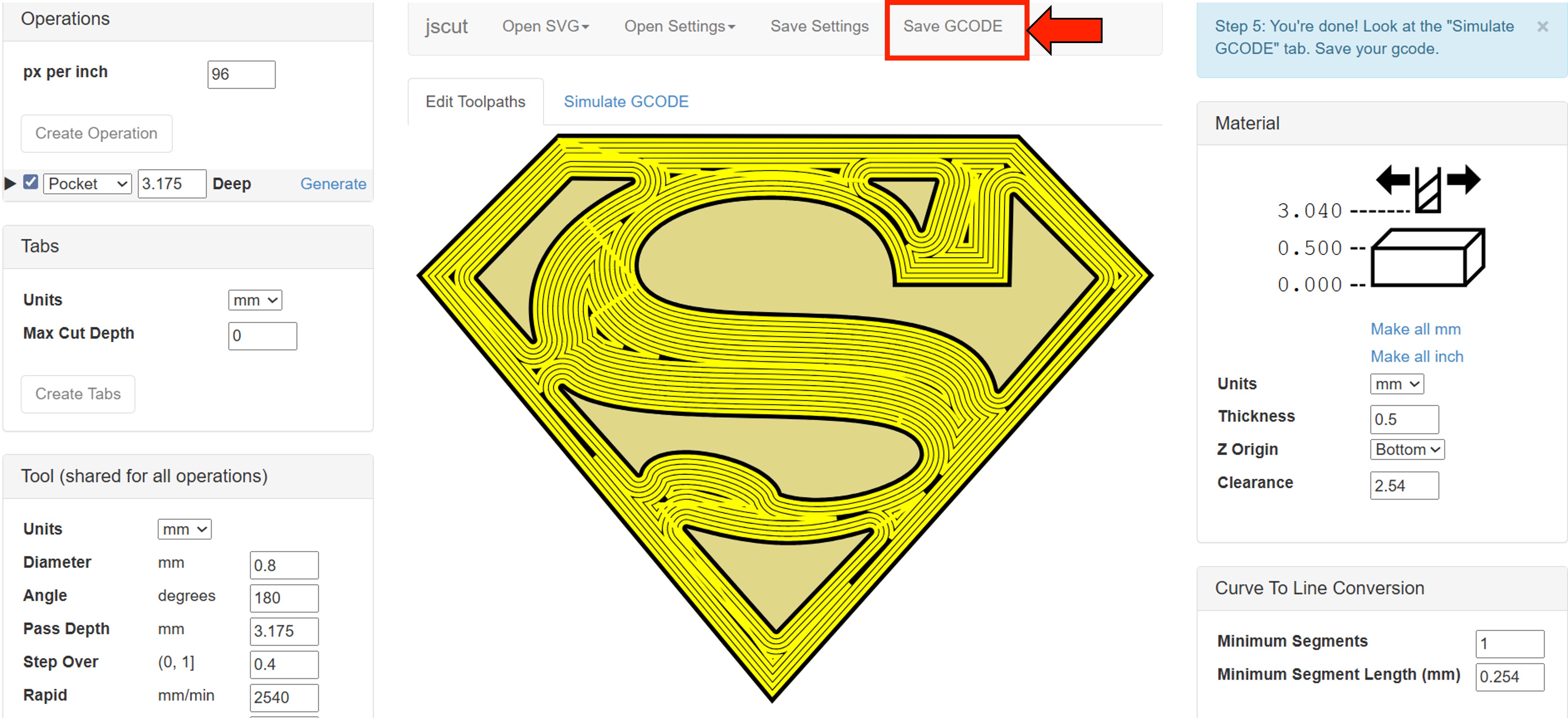
After that, in the same section, click on “Generate” to create the toolpath. After that, simply click “Save G-code.”
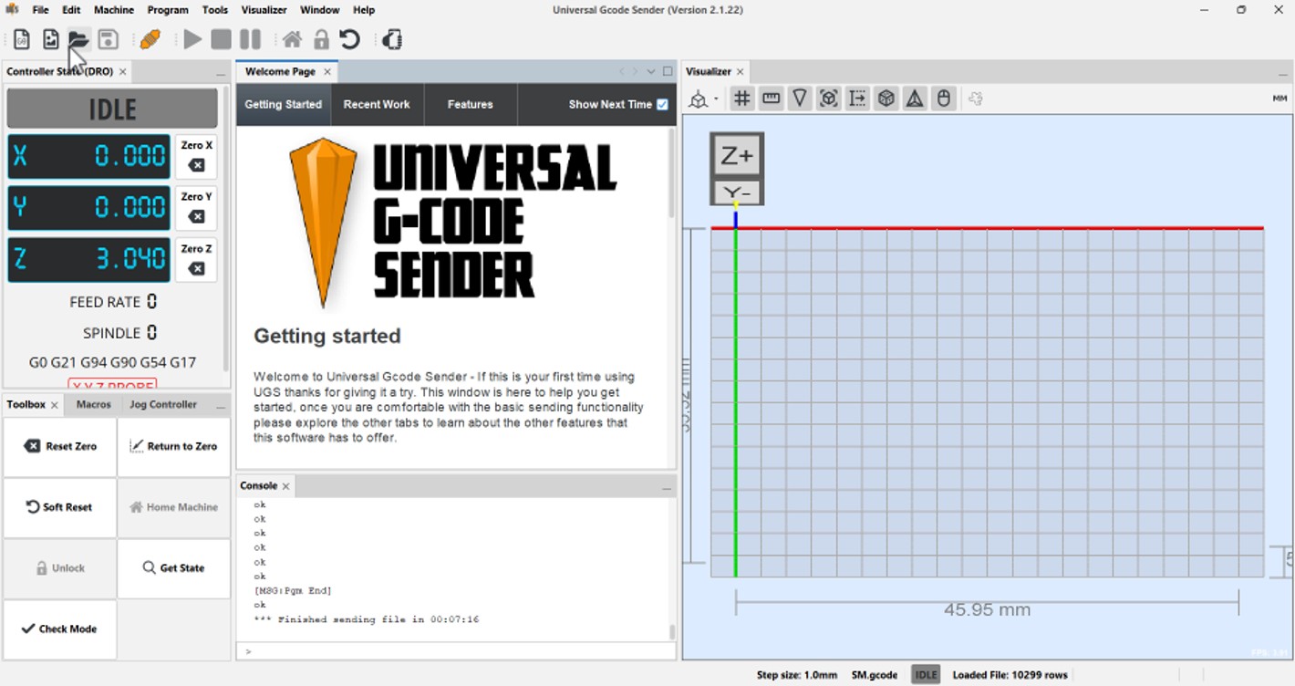
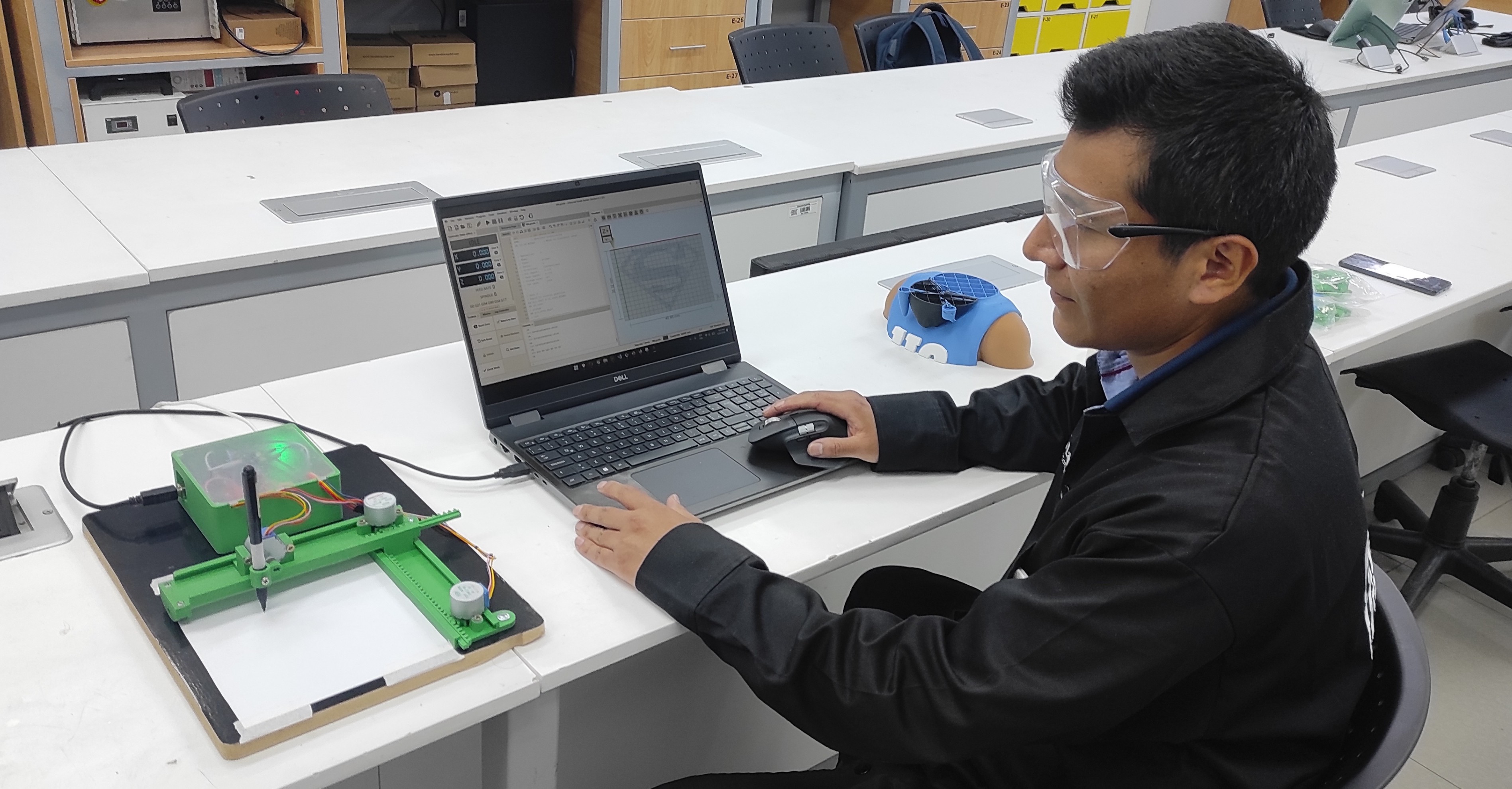
Universal G-Code Sender
Universal G-Code Sender (UGS) is a free, open-source program used to control CNC machines.
What it does
- Sends G-code (machine instructions) from your computer to a CNC machine
- Lets you move the machine manually (jog controls)
- Shows a preview of the toolpath
- Allows you to start, pause, or stop a job
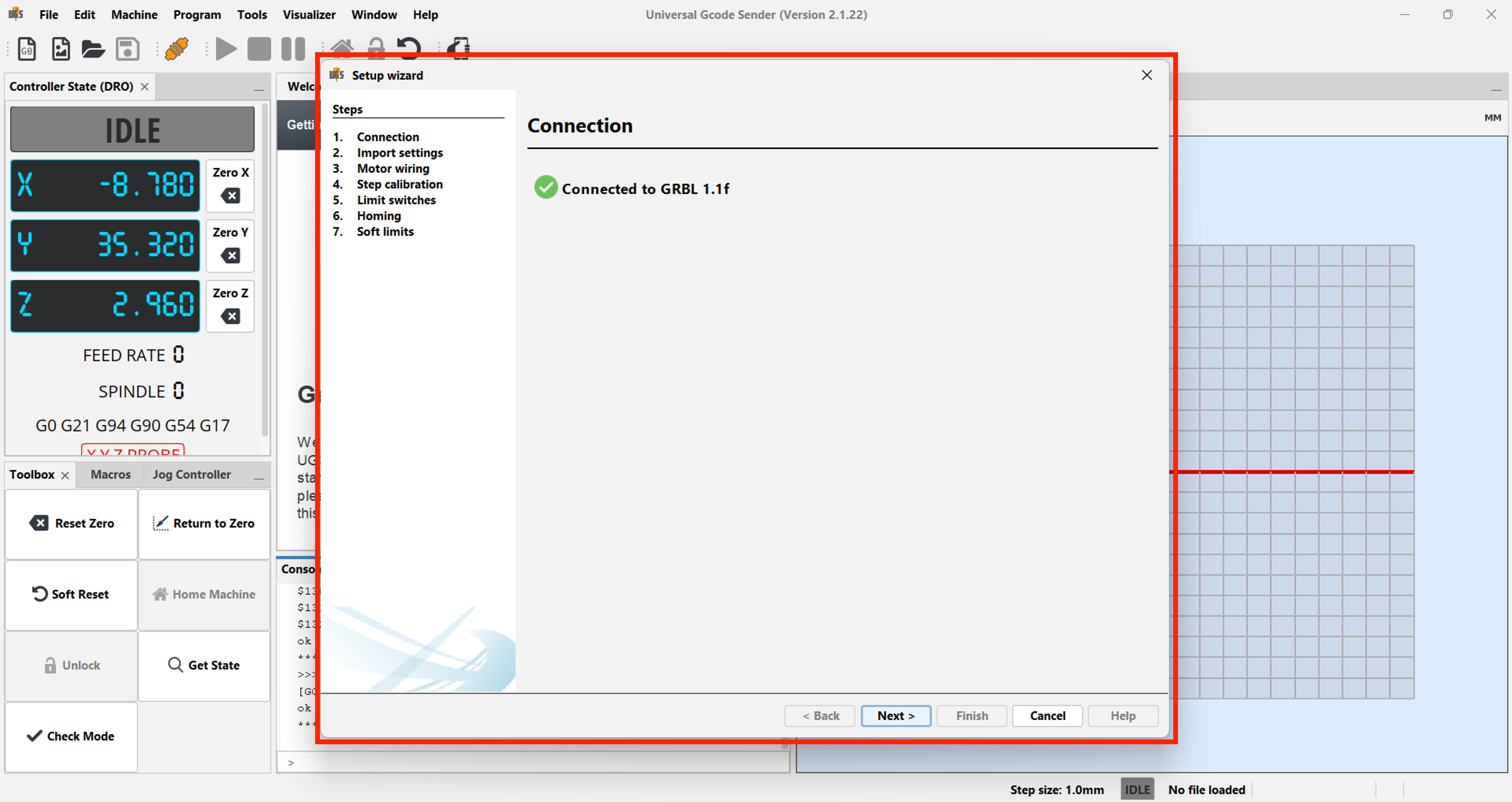
To use UGS, you need to connect your CNC machine to your computer via USB.
First, we need to configure the machine. To do this, go to the Machine menu and select “Setup Wizard.”
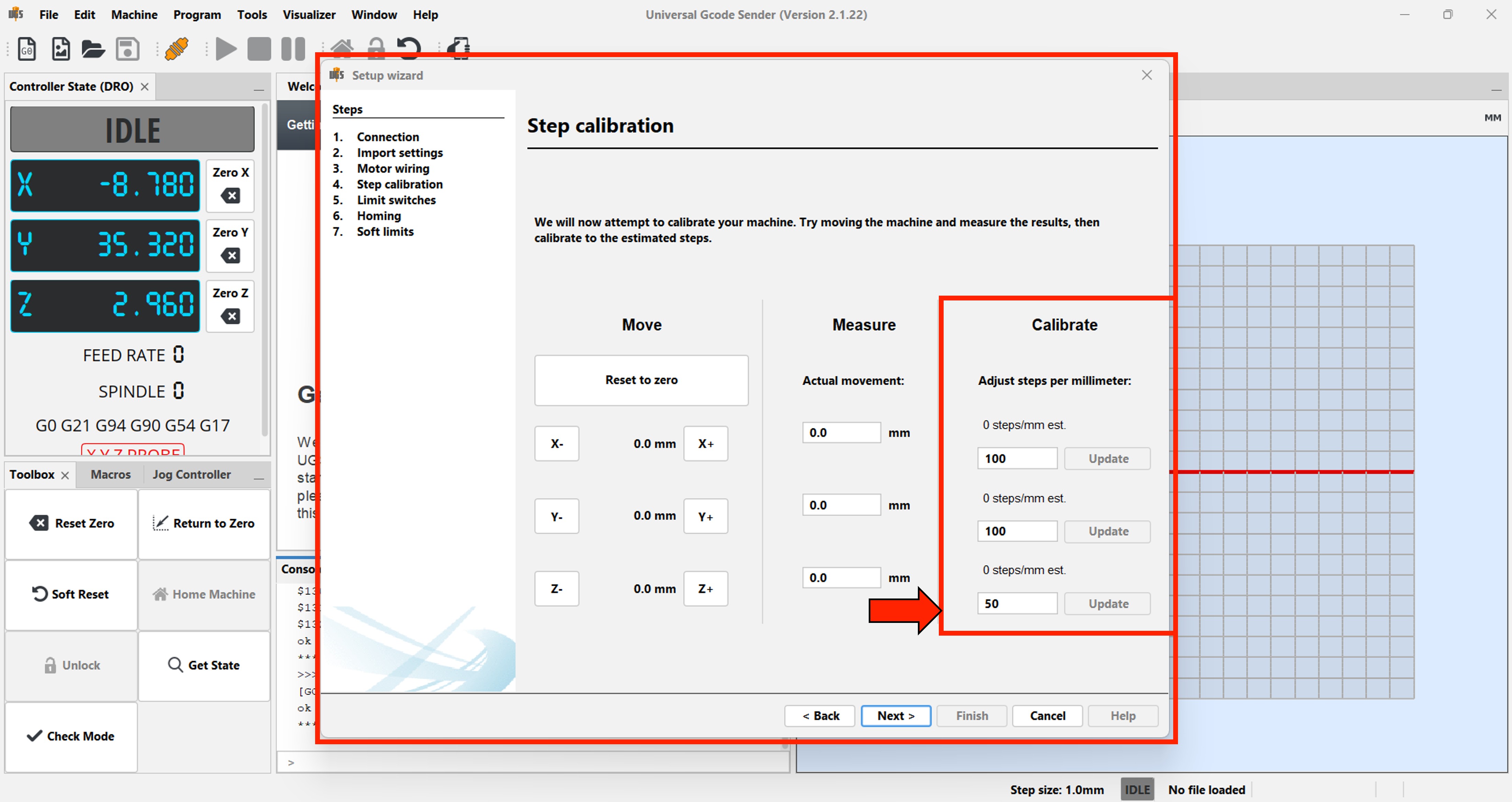
In the calibration step, enter the values shown below and set the zero (home) position.
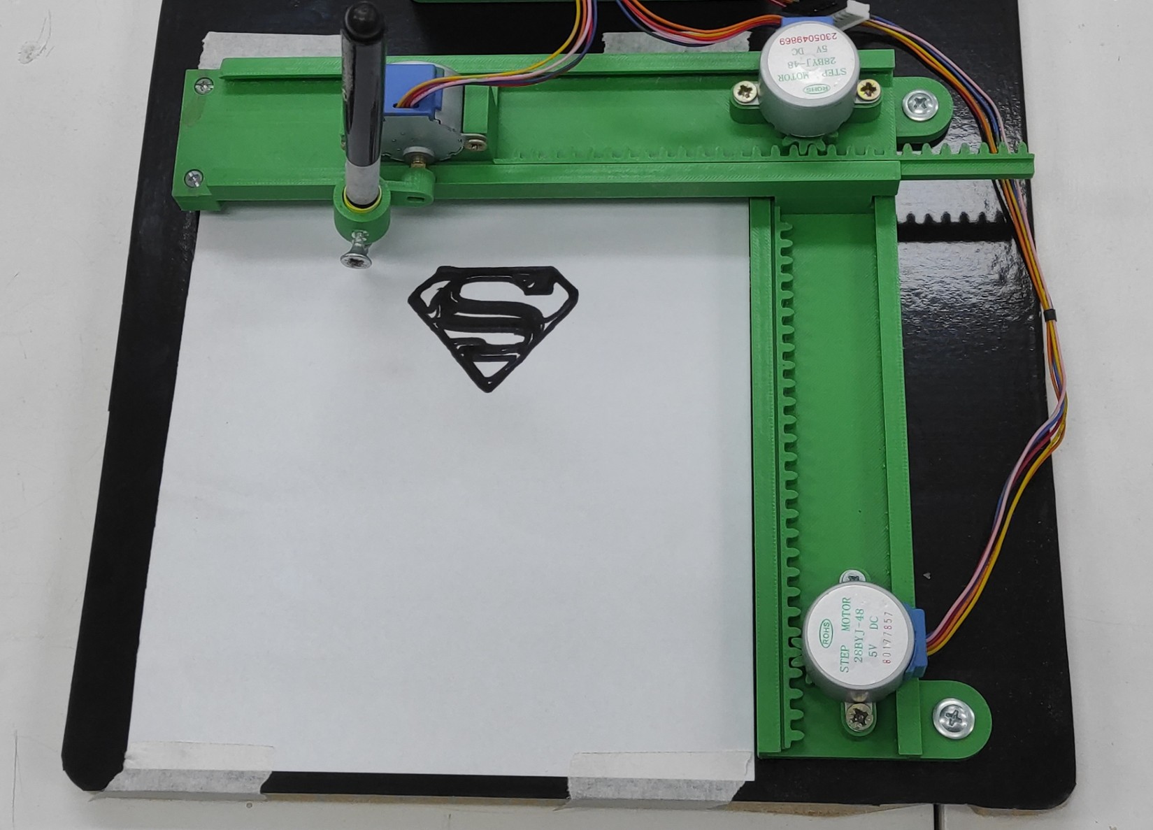
We will load the G-Code file that we generated with the JsCut application.
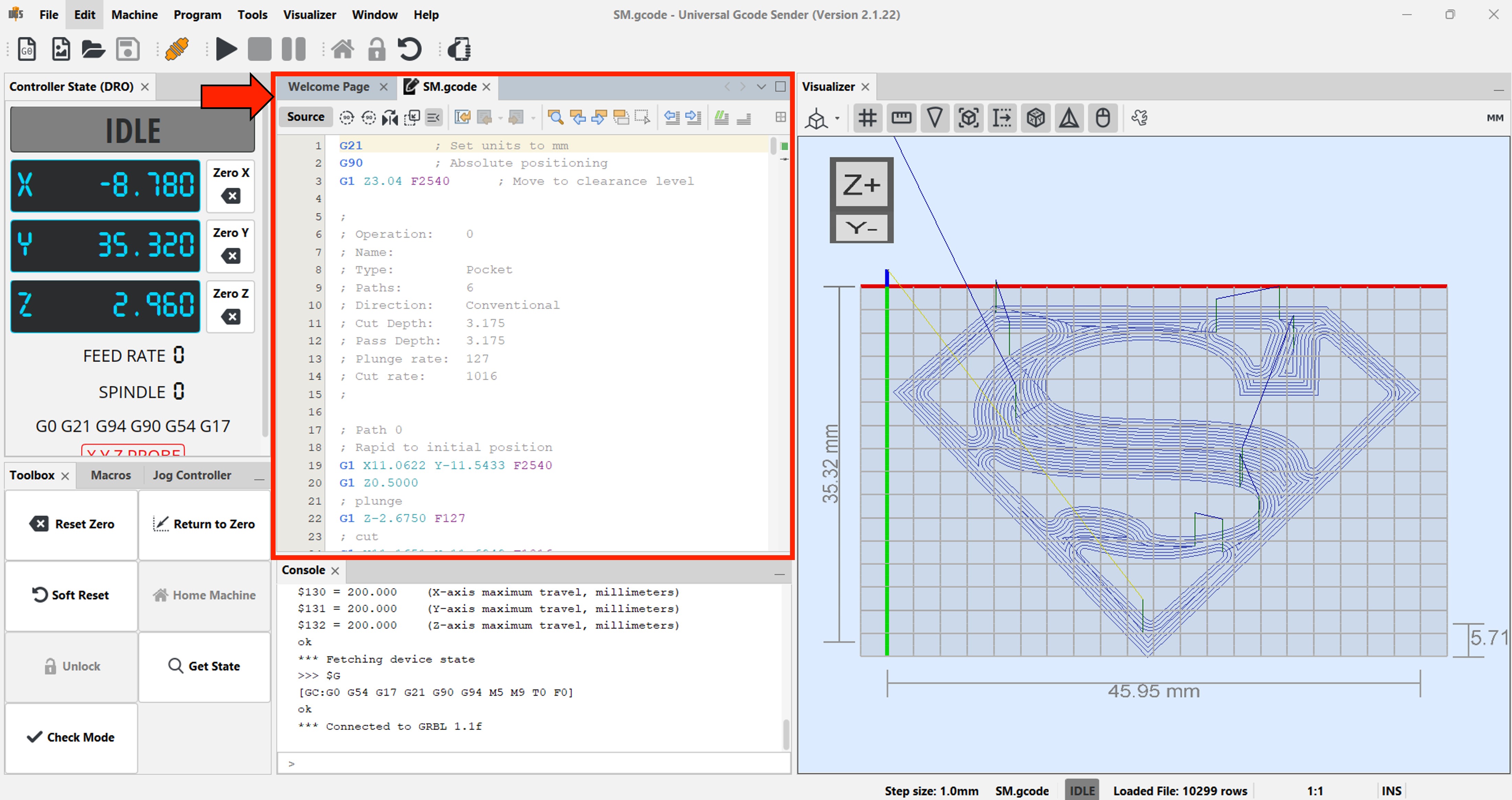
The plotter will handle the rest.
Problems and Difficulties
During the development and assembly of the mini CNC plotter, several challenges were encountered:
- Mechanical alignment issues Ensuring smooth and accurate movement across all axes required careful alignment of the 3D-printed parts.
- Limited precision of 28BYJ-48 motors The internal gear system introduces backlash, which can affect drawing accuracy.
- Wiring complexity Properly connecting the motors, drivers, and controller required attention to avoid incorrect connections.
- Firmware configuration Setting up and tuning the firmware (GRBL modification) for unipolar stepper motors was not straightforward.
- Calibration process Adjusting steps per millimeter and movement limits was necessary to achieve acceptable results.
- Structural rigidity Since the machine is fully 3D printed, maintaining stability and reducing vibrations was a challenge.
Files
Here are the files available for download.