Mini CNC Pen plotter
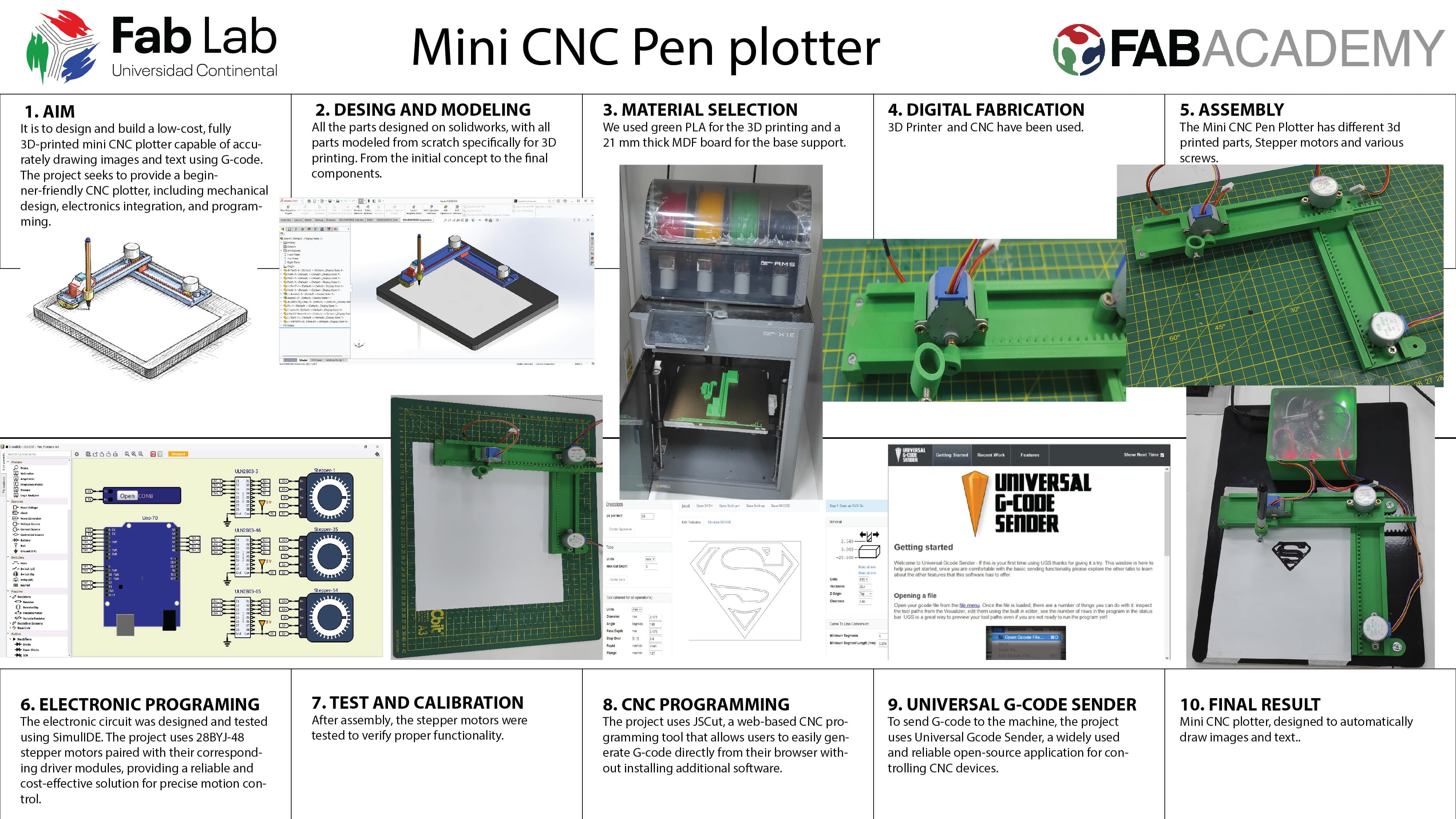
Mini CNC plotter, designed to automatically draw images and text. It uses stepper motors and 3D-printed parts to control movement across three axes (X, Y, and Z). By converting images into G-code, the machine can accurately reproduce drawings on paper. It is an affordable and beginner-friendly project that introduces the basics of CNC machines, electronics, and programming.
Mini CNC Plotter – Compact, Affordable, and Easy to Build
Built with simplicity and accessibility in mind, this plotter requires no metal parts—every structural component can be 3D printed. The design uses affordable, easy-to-find motors and components, making it a cost-effective option for hobbyists, students, and makers.
Key Features:
Fully 3D-printed structure – no metal parts required
Compact, lightweight, and easy to carry
Simple assembly and beginner-friendly design
Uses low-cost, widely available stepper motors
Open-source and completely free to use and customize
Precise three-axis (X, Y, Z) movement for accurate drawings
G-code compatible for converting images and text into drawings
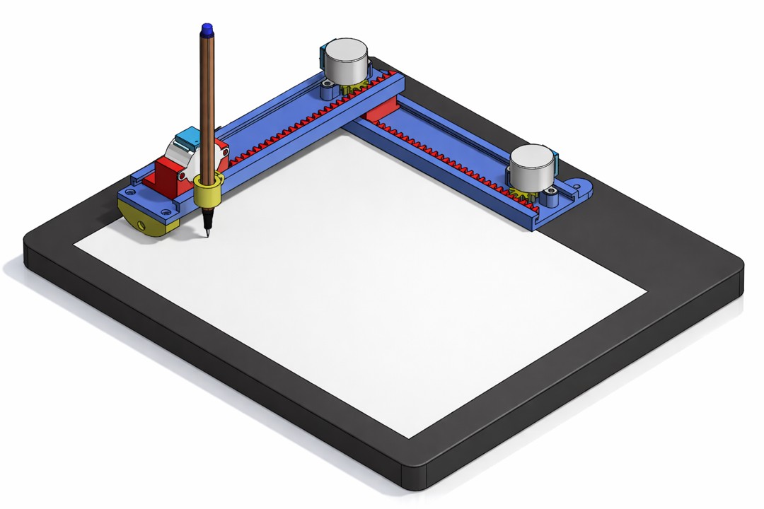
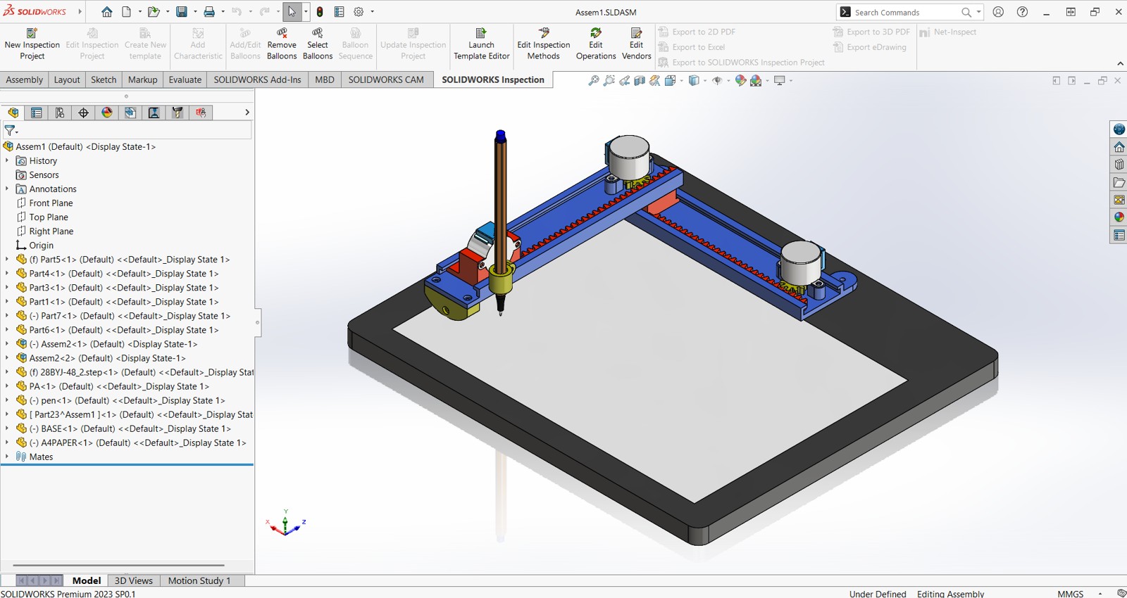
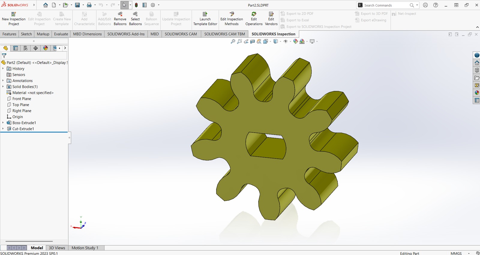
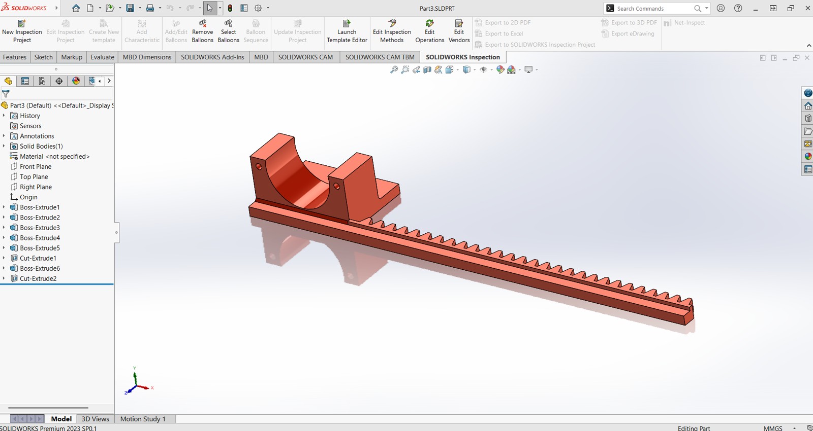
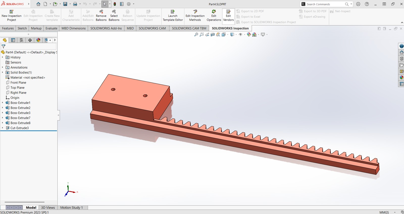
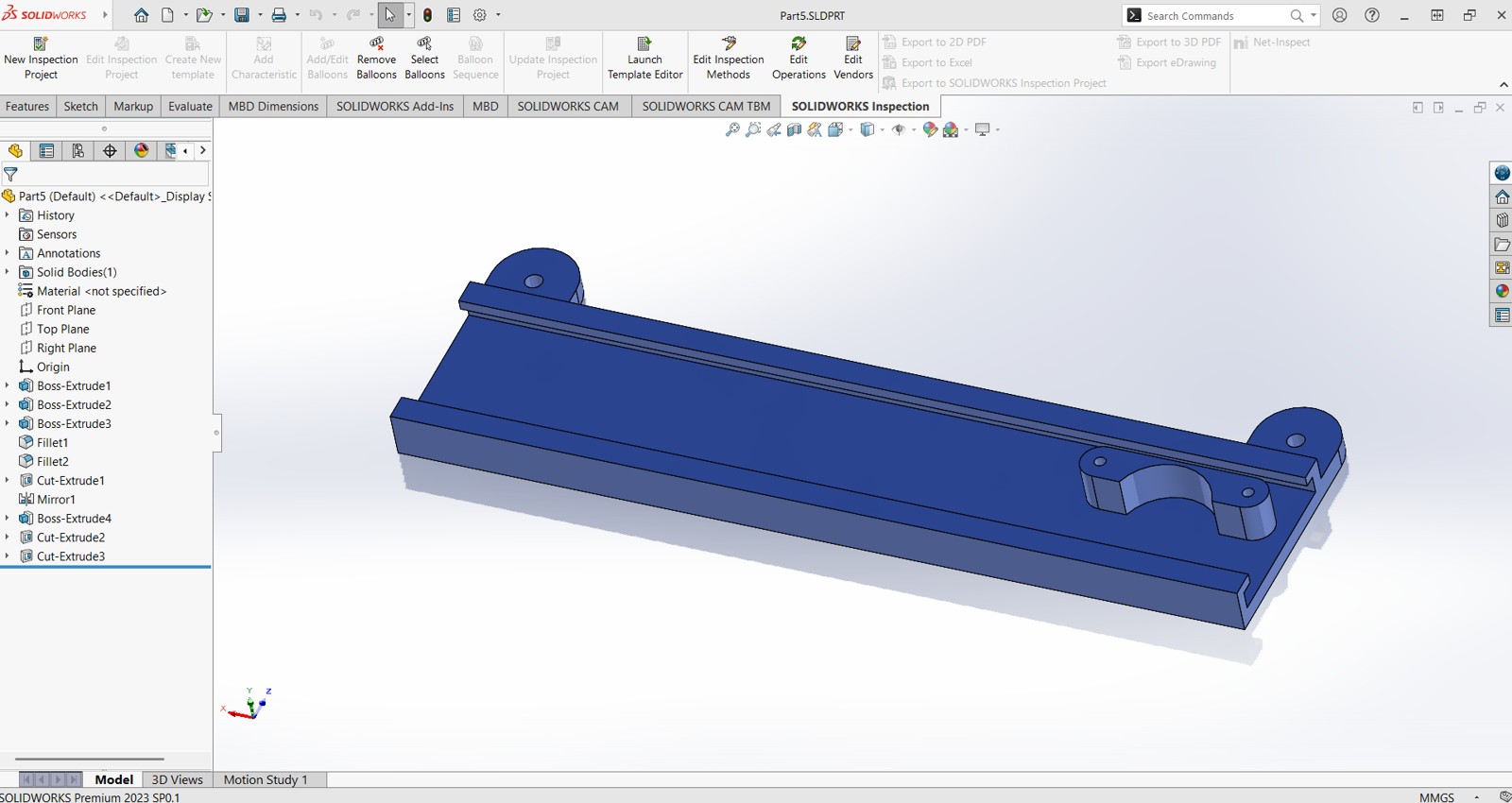
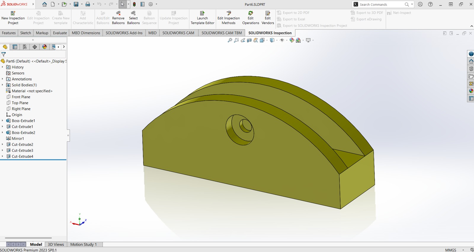
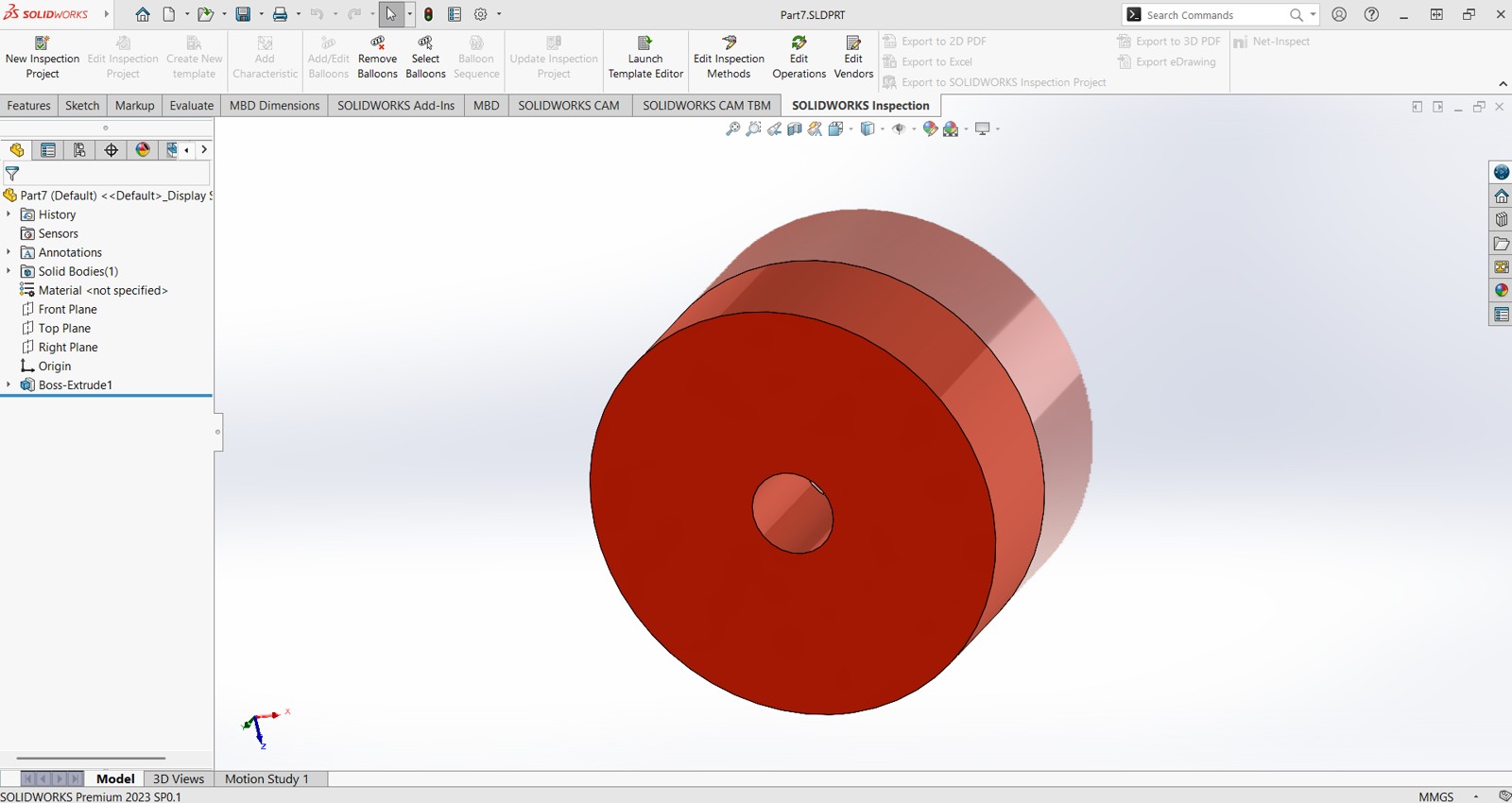
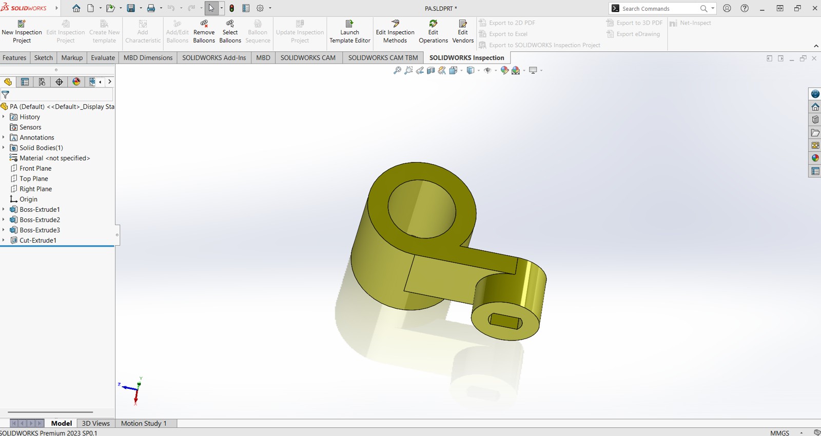
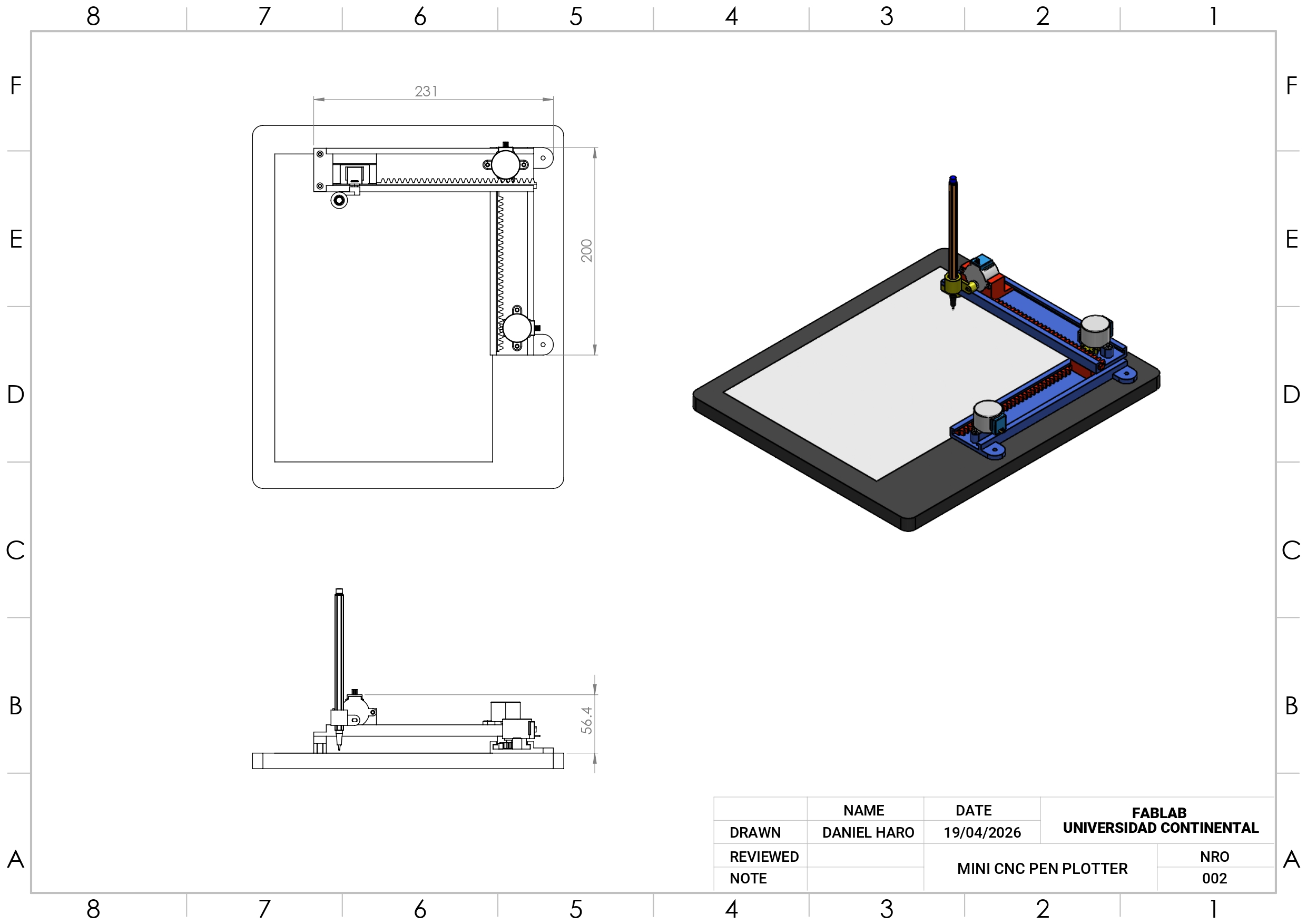
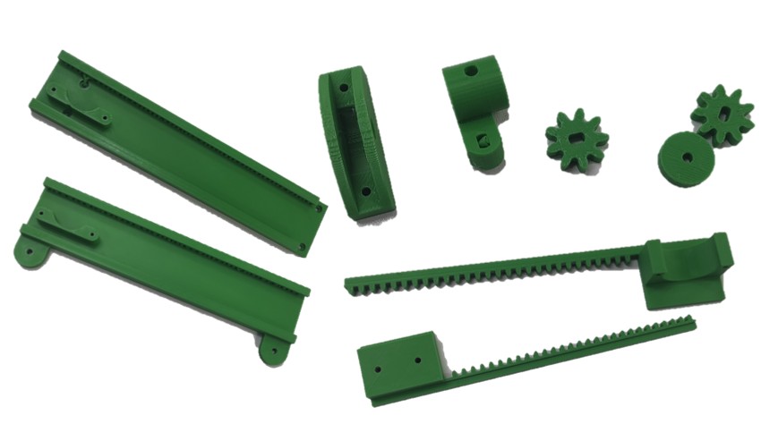
Mechanical Design
The entire design was created in SolidWorks, with all parts modeled from scratch specifically for 3D printing. From the initial concept to the final components, every detail was carefully developed to ensure functionality and ease of fabrication. The design is fully customizable, allowing you to modify dimensions as needed to suit your requirements.
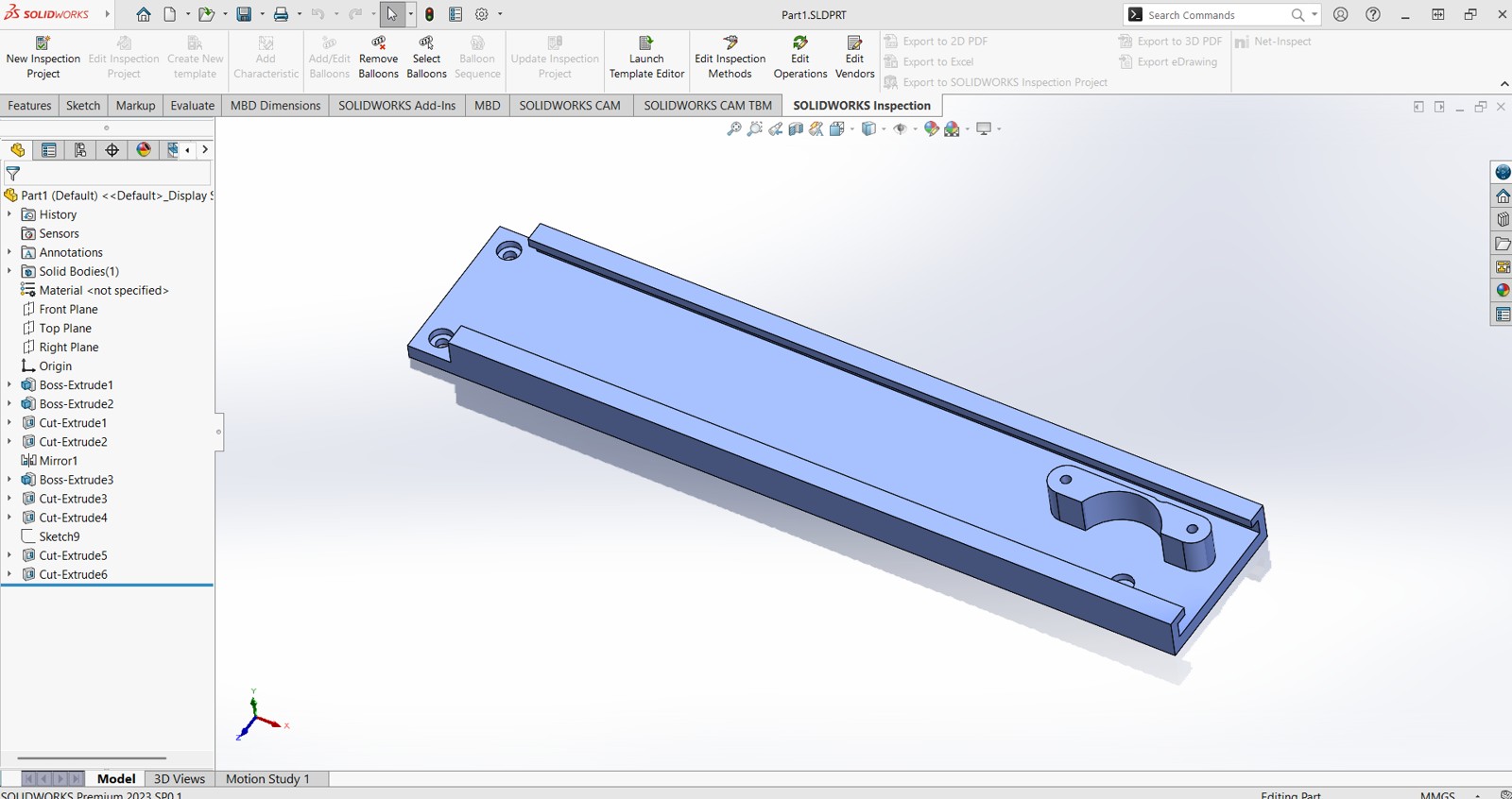
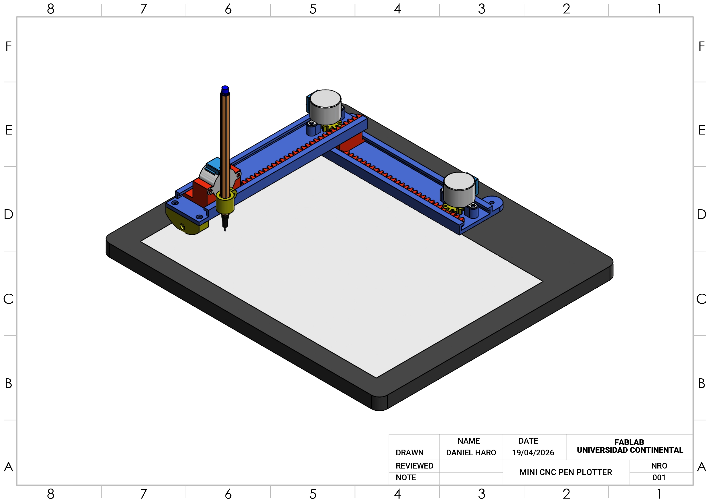
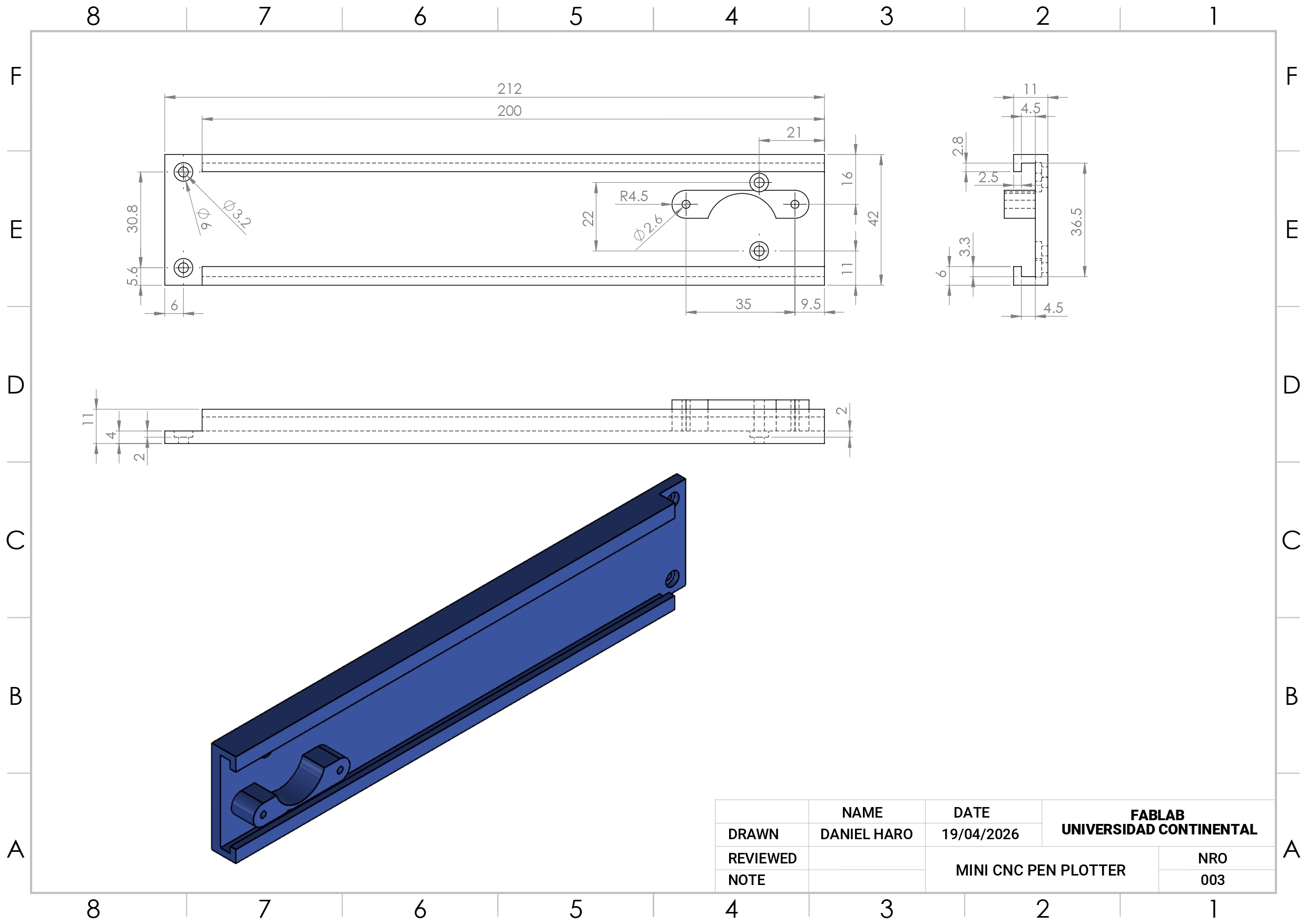
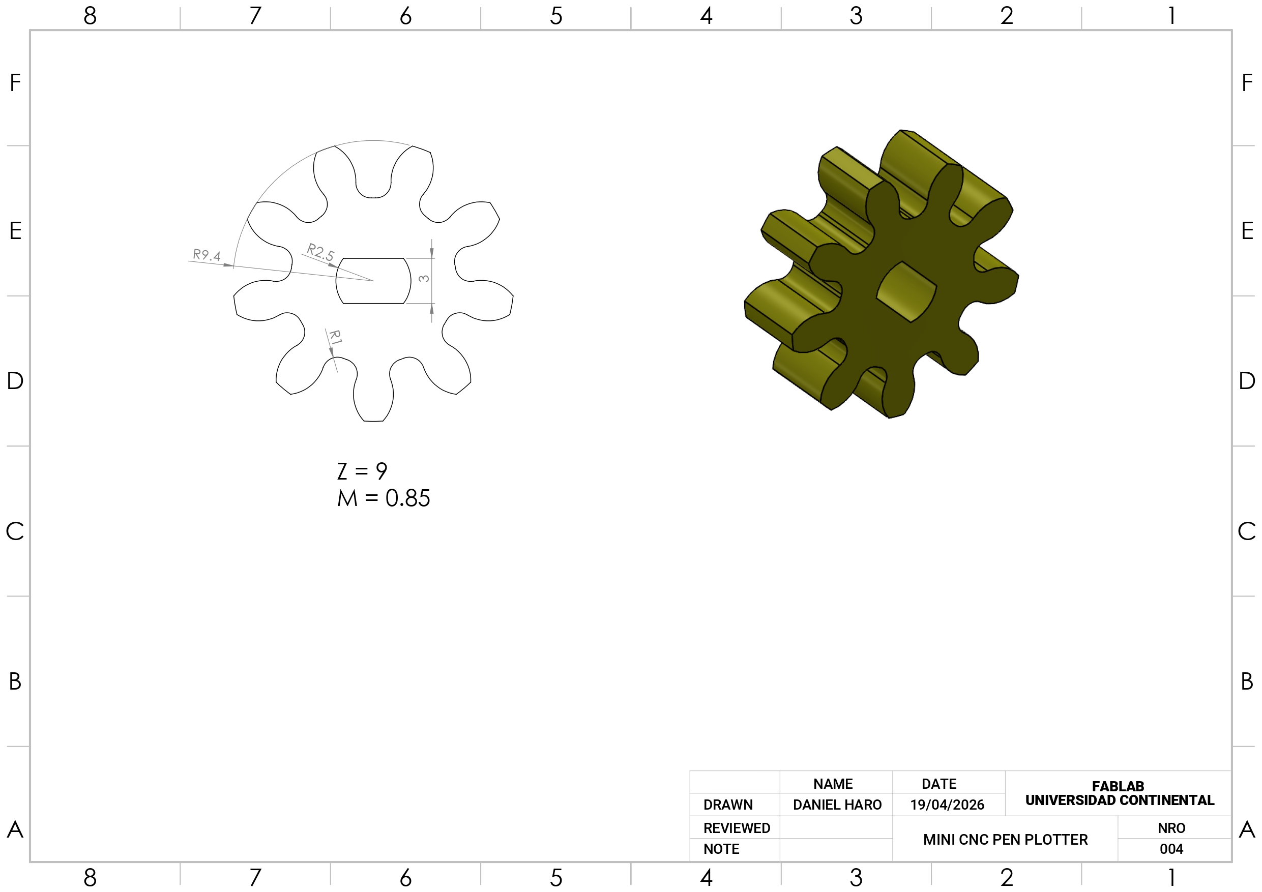
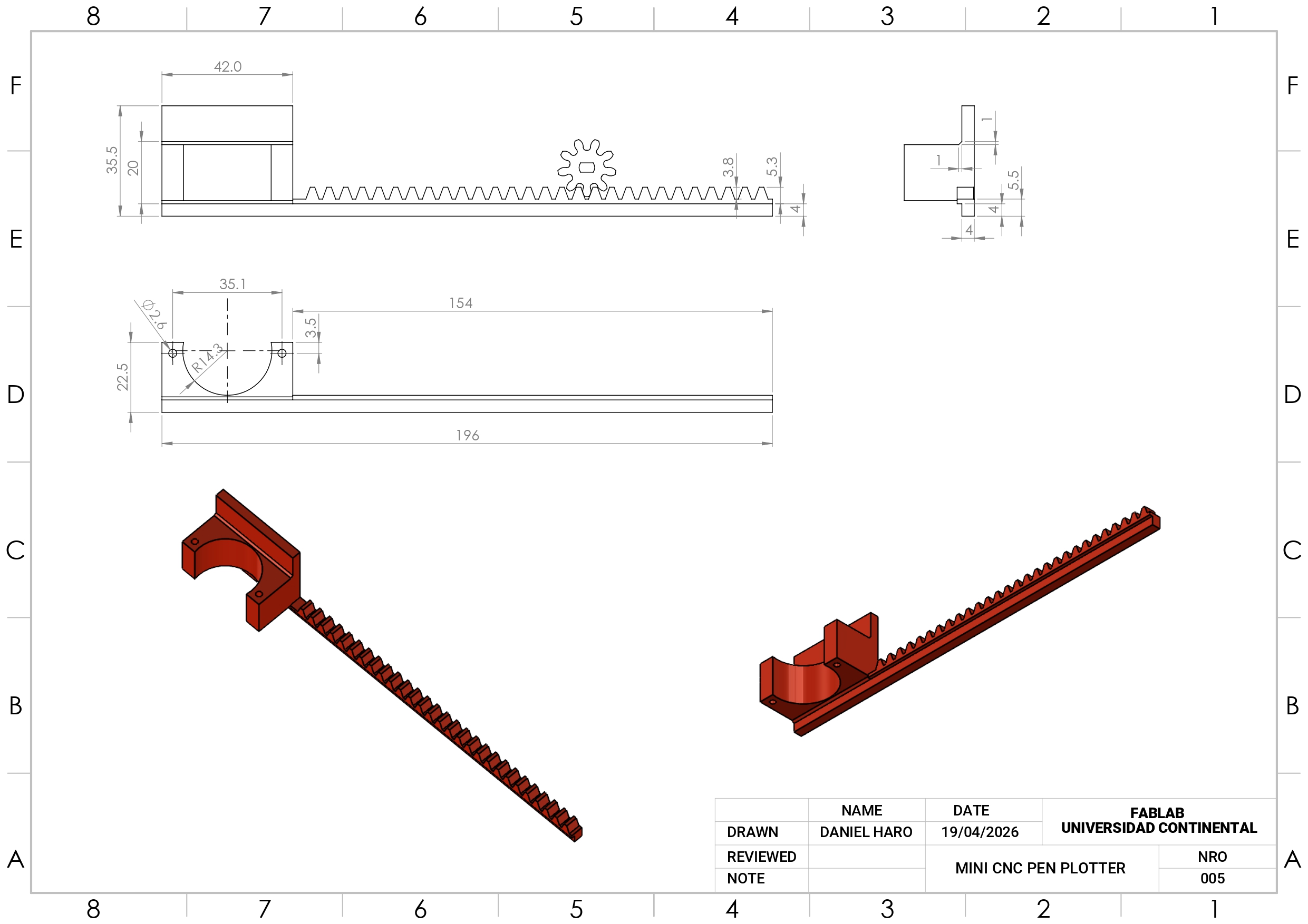
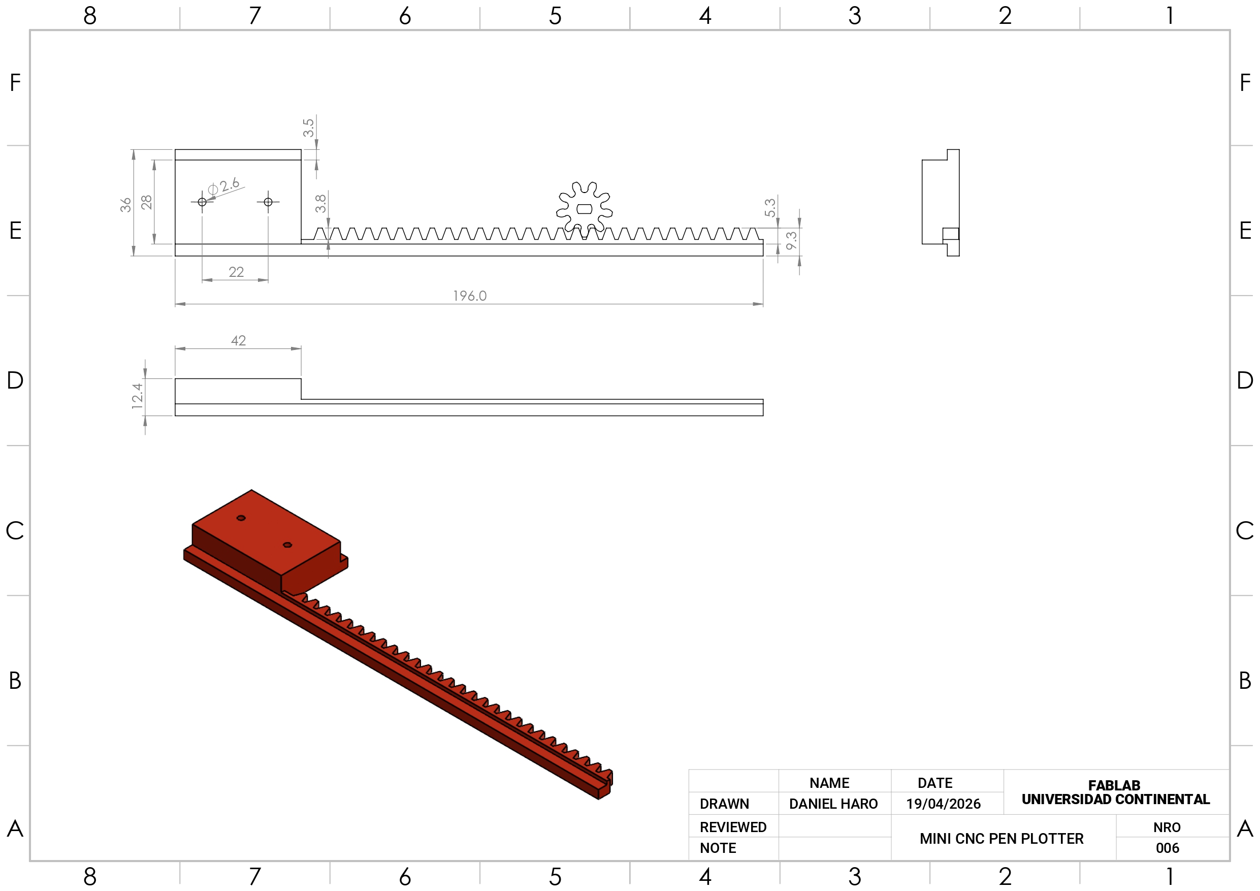
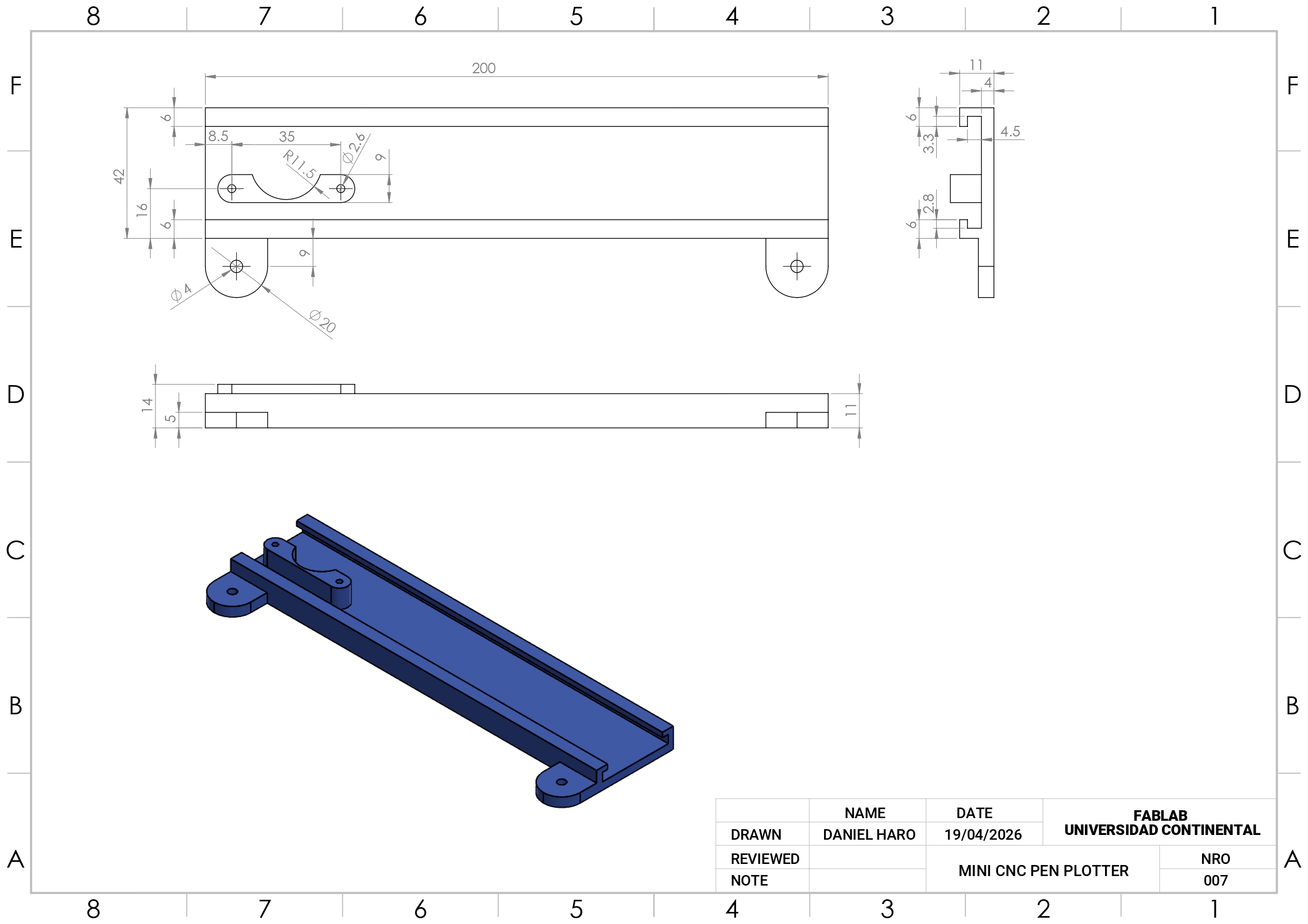
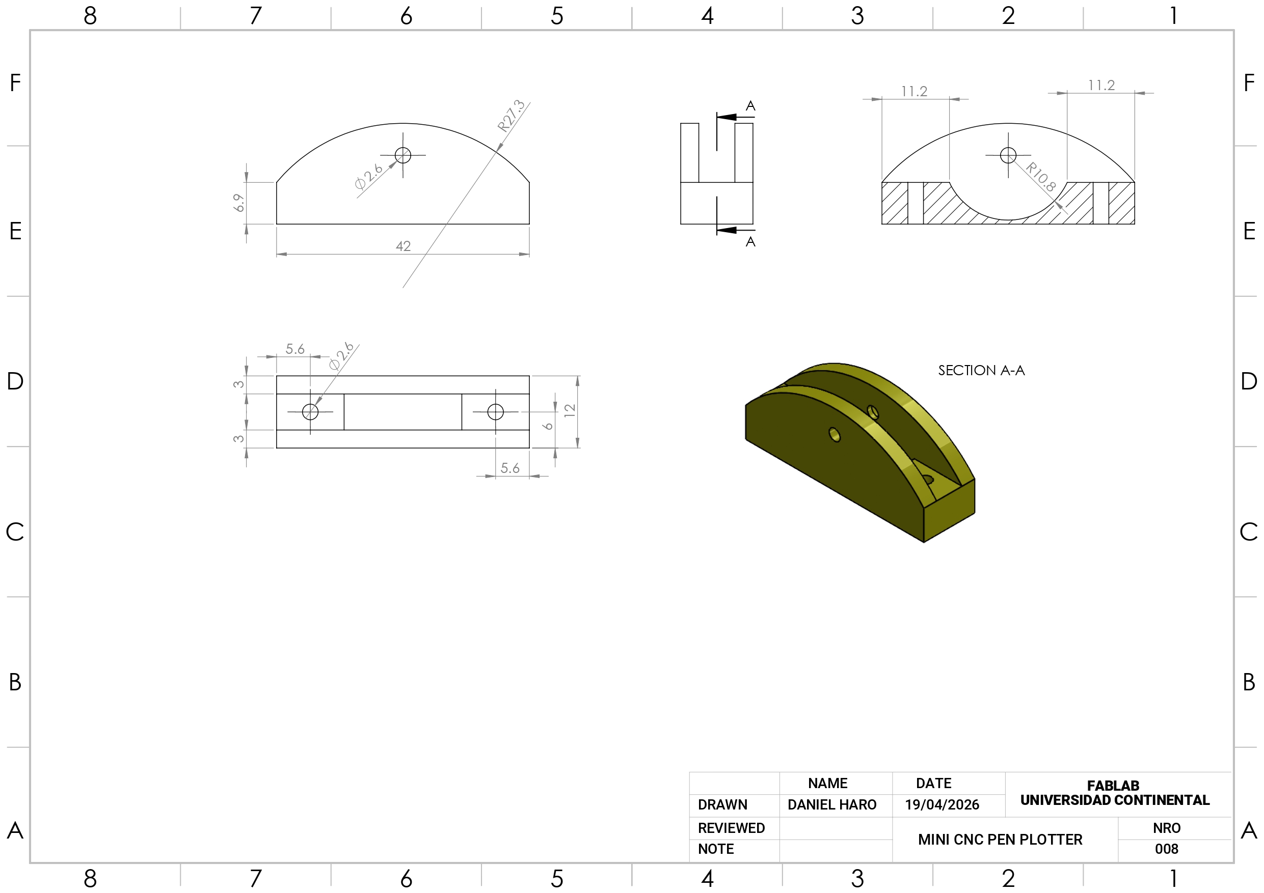
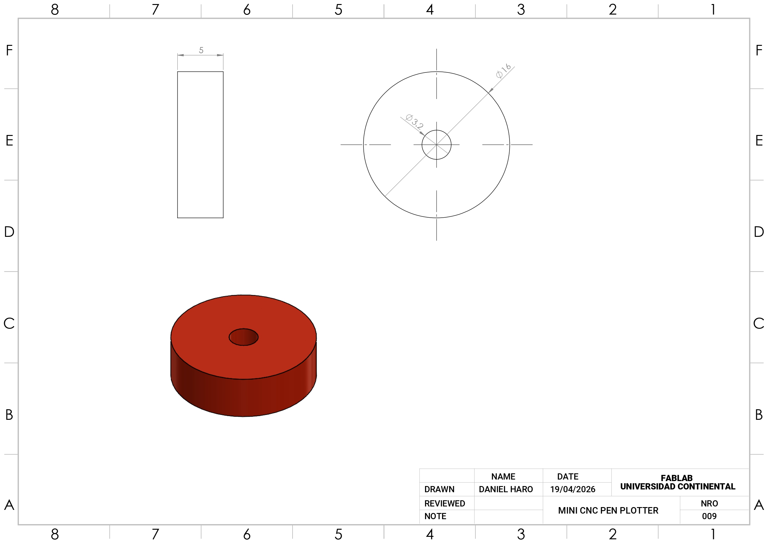
Mechanical Drawings
All technical drawings were also created in SolidWorks, ensuring consistency and precision throughout the entire design process. Each drawing is fully detailed and aligned with the 3D models, making it easy to understand dimensions, assembly, and part relationships. If needed, the drawings can be recreated, adjusted, or redesigned from scratch, allowing flexibility to adapt the project to new specifications or improvements.
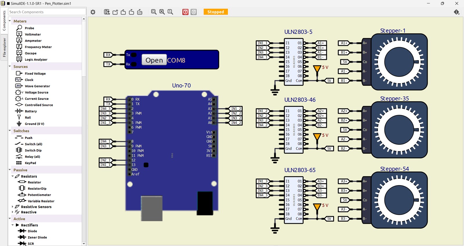
Electronic Circuit
The electronic circuit was designed and tested using SimulIDE, a free and open-source software for electronic simulation. This allowed us to validate the system’s behavior and ensure proper functionality before building the physical circuit.
The project uses 28BYJ-48 stepper motors paired with their corresponding driver modules, providing a reliable and cost-effective solution for precise motion control. For the main controller, an Arduino Nano or Arduino Uno is used, offering flexibility depending on availability and user preference.
This combination of accessible components and open-source tools makes the system easy to understand, modify, and replicate, making it ideal for beginners and educational purposes.
Control Firmware
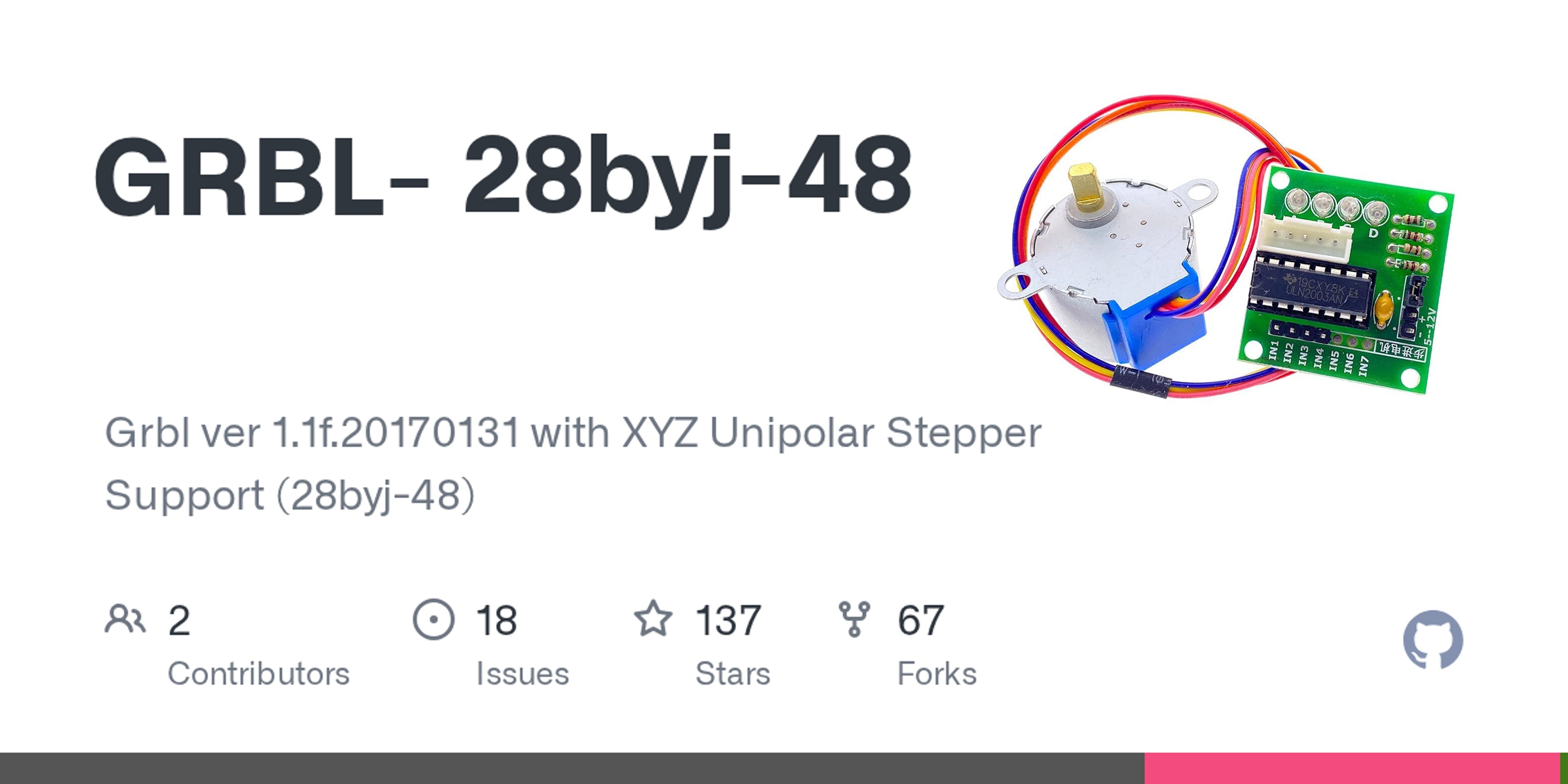
The repository GRBL-28byj-48 GitHub repo is a modified version of GRBL (a popular CNC firmware) adapted to work with 28BYJ-48 unipolar stepper motors instead of the typical bipolar motors used in CNC machines.
Still based on GRBL → supports standard G-code workflows
Works with common CNC tools and senders
Easy to study, modify, and adapt for custom machines
Perfect for DIY plotters and educational CNC projects
Programming G-Code
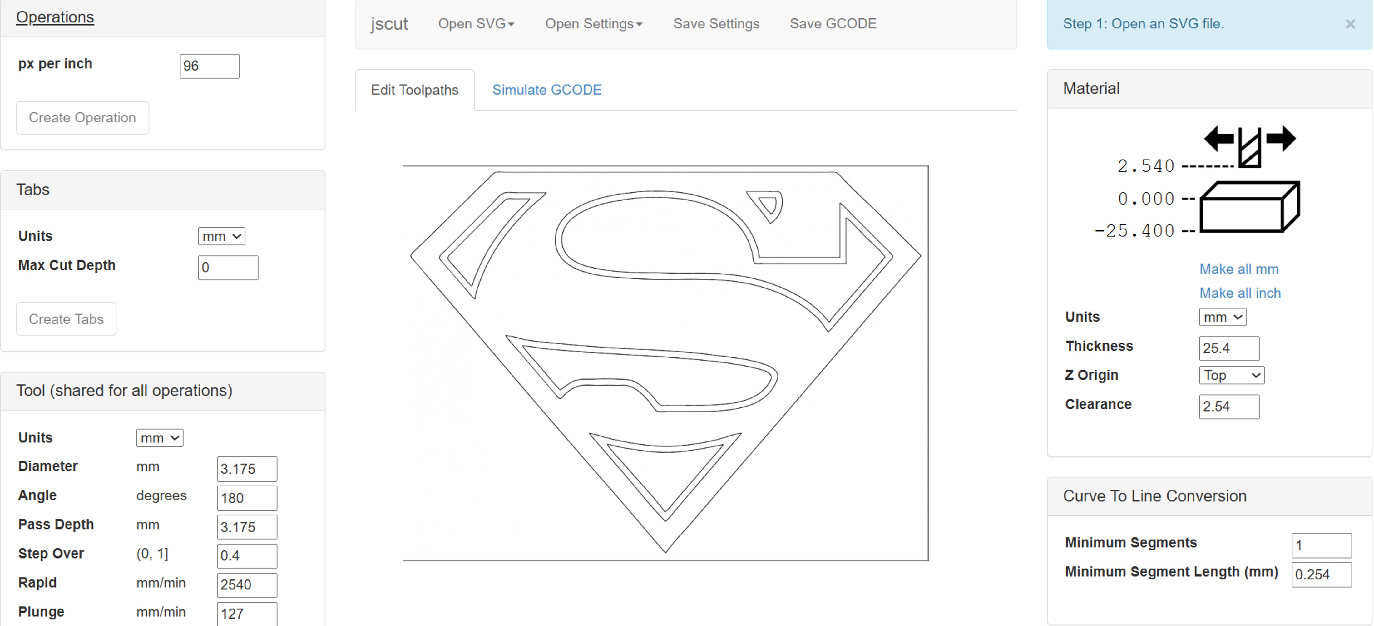
The project uses JSCut, a web-based CNC programming tool that allows users to easily generate G-code directly from their browser without installing additional software. This makes the workflow simple and accessible, especially for beginners.
With JSCut, users can import vector designs (such as SVG files), define cutting or drawing paths, and convert them into G-code compatible with the plotter. Its intuitive interface helps simplify the process of preparing files, adjusting parameters, and previewing toolpaths before execution.
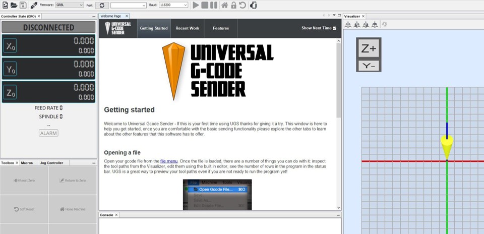
Universal G-Code Sender
To send G-code to the machine, the project uses Universal Gcode Sender, a widely used and reliable open-source application for controlling CNC devices.
Universal Gcode Sender provides a simple and intuitive interface to connect the computer to the Arduino-based controller via USB. It allows users to load G-code files, start and pause jobs, and monitor the machine’s status in real time. Additionally, it includes useful features such as manual controls (jogging), command input, and visual feedback of the toolpath.
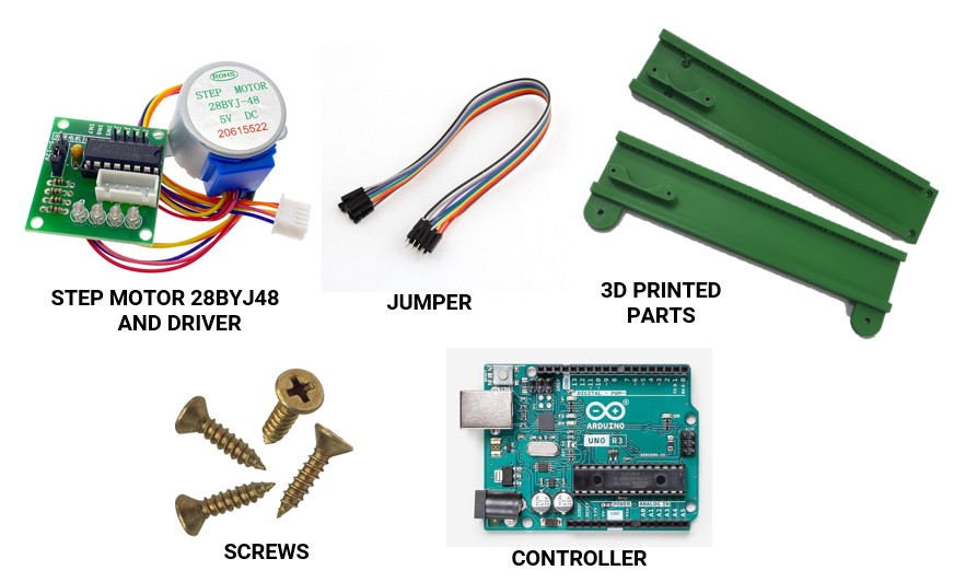
Project Materials
The mini CNC plotter is built using simple, affordable, and easy-to-find components:
- 28BYJ-48 Stepper Motors with Driver Modules
Provide precise motion control for the X, Y, and Z axes.
- Jumper Wires Used to connect the electronic components quickly and efficiently.
- 3D Printed Parts All structural components are fully 3D printed, making the machine lightweight and easy to replicate.
- Screws and Fasteners Standard screws are used for assembling and securing the structure.
- Controller (Arduino Uno or Nano) Acts as the main control unit, executing G-code commands and coordinating motor movements.
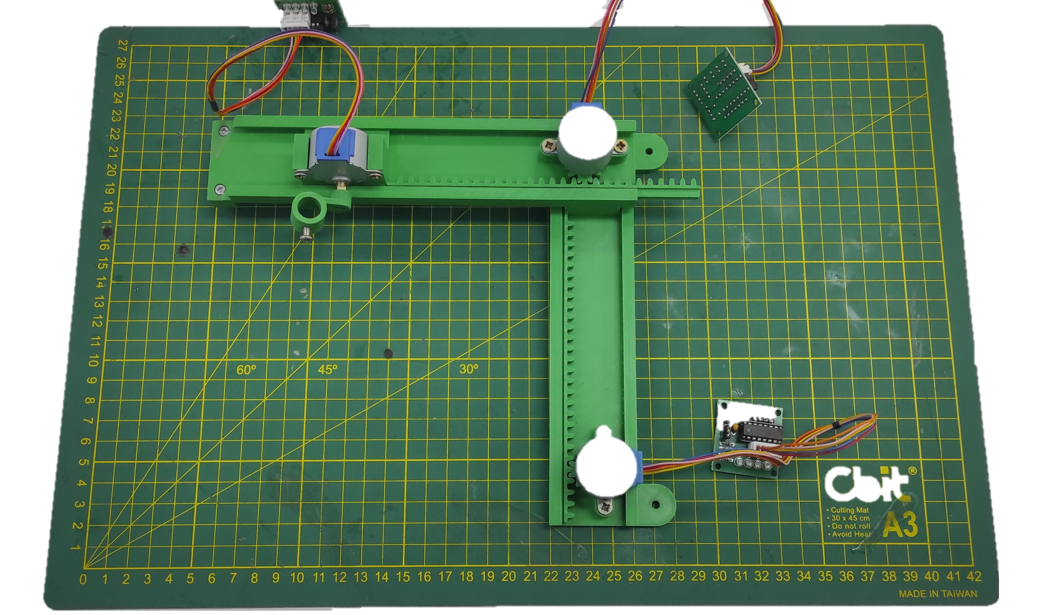
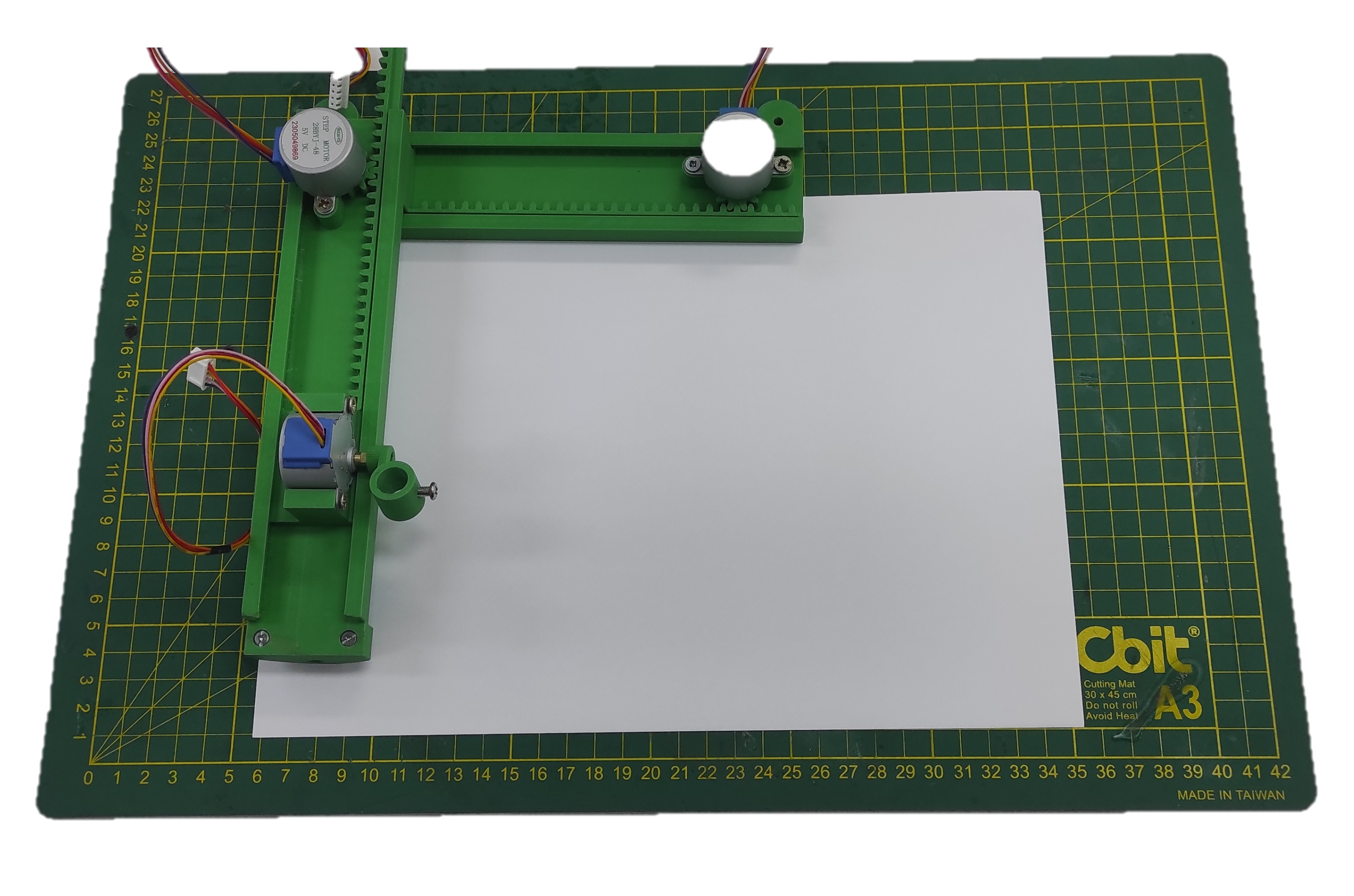
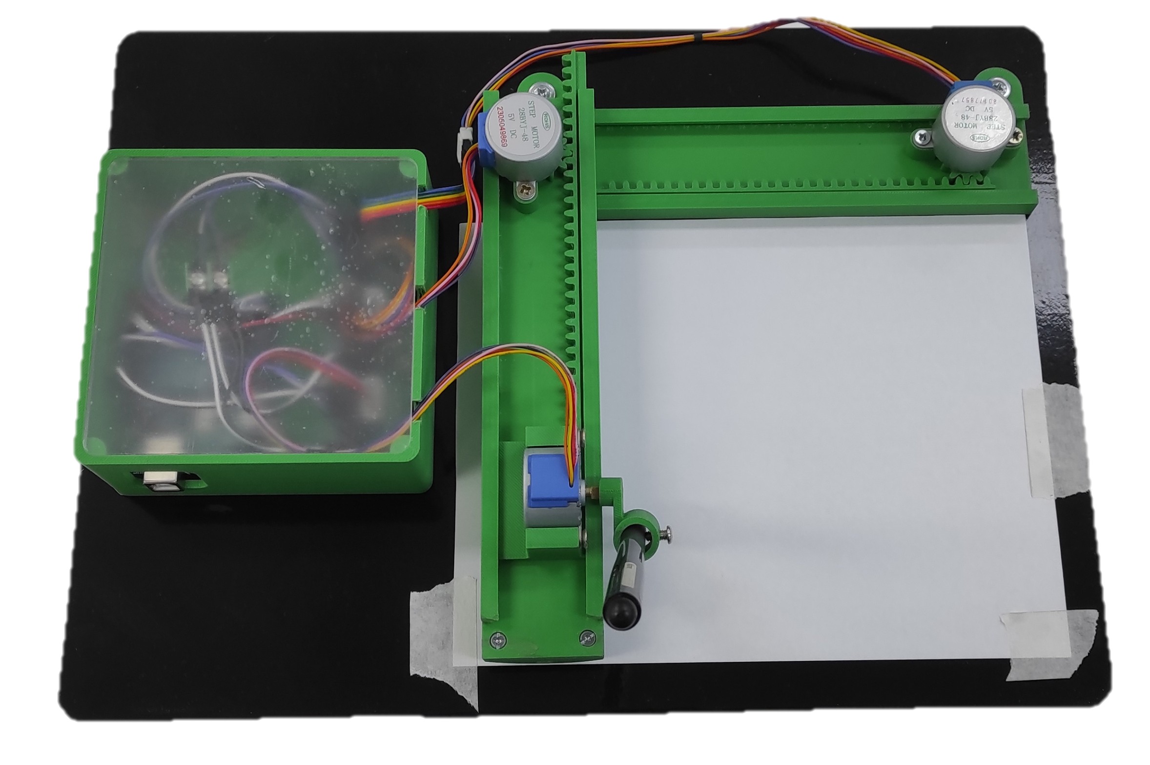
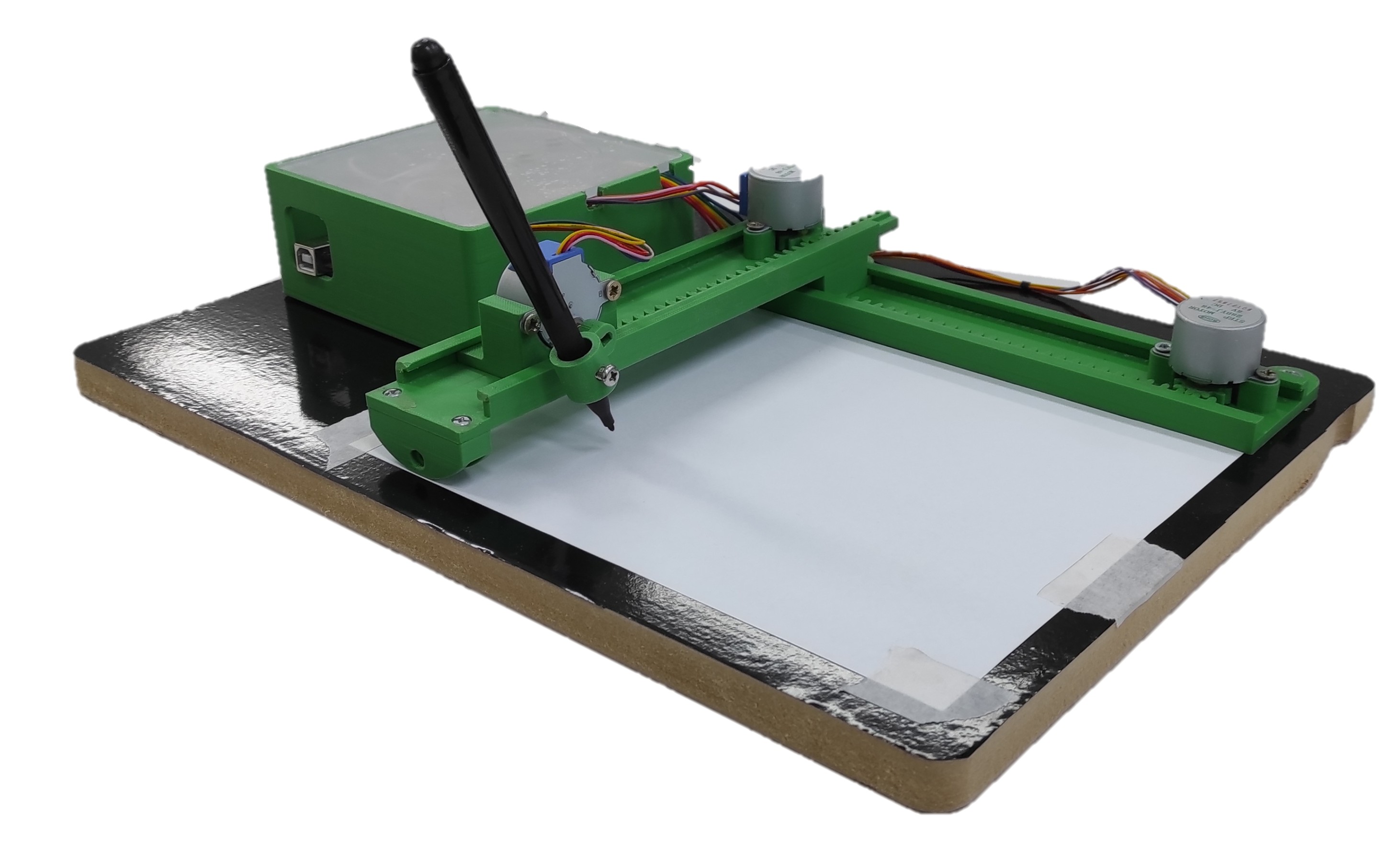
Project Images
Below are some images captured during the assembly of the mini CNC plotter. These photos document different stages of the build process, from initial component setup to the final assembly.
They provide a visual reference for how the parts come together, helping users better understand the structure, wiring, and overall construction of the machine. These images can also serve as a practical guide for anyone attempting to replicate or modify the project.
Problems and Difficulties
During the development and assembly of the mini CNC plotter, several challenges were encountered:
- Mechanical alignment issues Ensuring smooth and accurate movement across all axes required careful alignment of the 3D-printed parts.
- Limited precision of 28BYJ-48 motors The internal gear system introduces backlash, which can affect drawing accuracy.
- Wiring complexity Properly connecting the motors, drivers, and controller required attention to avoid incorrect connections.
- Firmware configuration Setting up and tuning the firmware (GRBL modification) for unipolar stepper motors was not straightforward.
- Calibration process Adjusting steps per millimeter and movement limits was necessary to achieve acceptable results.
- Structural rigidity Since the machine is fully 3D printed, maintaining stability and reducing vibrations was a challenge.
Project Documentation
The complete project documentation is attached, covering design, electronics, firmware, and assembly instructions.