## 1. CAD Tools Comparison In this week we're exploring multiple tools and software. The first step for me was to model something related to my final project. I focused on comparing software I am comfortable with versus open-source and new software introduced this week. **For 3D:** Fusion vs. FreeCAD **For 2D:** Illustrator vs. Inkscape and Photoshop/Photopea.com ### Goals and Outcomes 1. Model a part related to my final project. 2. Exercise parametric modelling on FreeCAD and Blender. 3. Create a Vector diagram demonstrating my workflow on Illustrator. 4. Create a Vector graphic on Inkscape. 5. Create a rastered poster of all results using Photoshop and Photopea.

## 3D Overview - Autodesk Fusion Fusion is my primary tool for mechanical design. The workflow followed a standard sketch-to-extrude process.
Fusion 360 Workflow
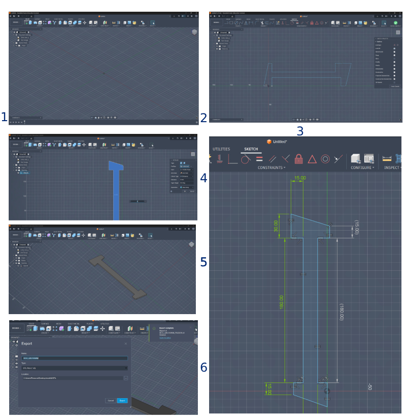
Figure 1: Designing the base geometry in Fusion 360.
## 3D Overview - FreeCAD FreeCAD offers powerful parametric control, though navigating the sketch interface was my first major challenge. I followed a tutorial on parametric modeling to better understand the spreadsheet-driven workflow.
Create Spreadsheet
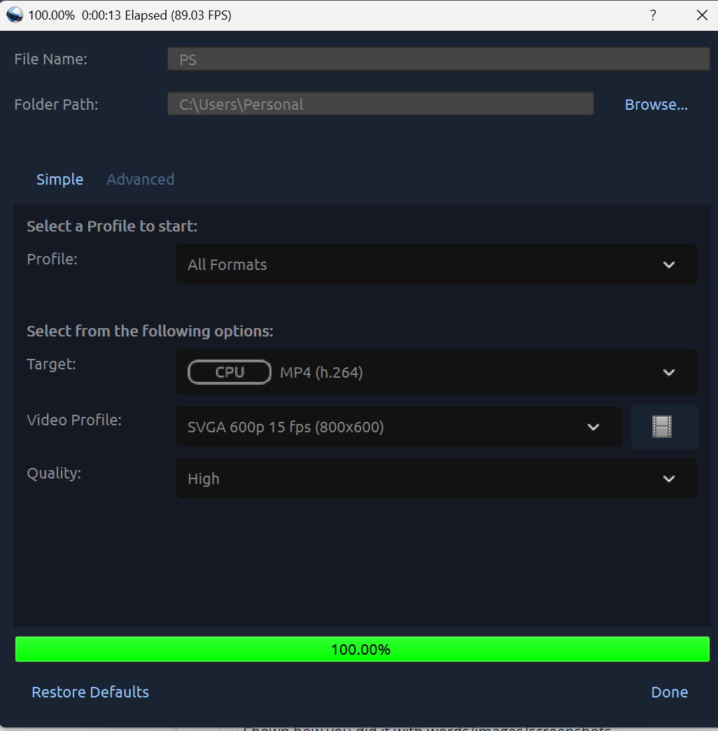
Importing the file to Inkscape
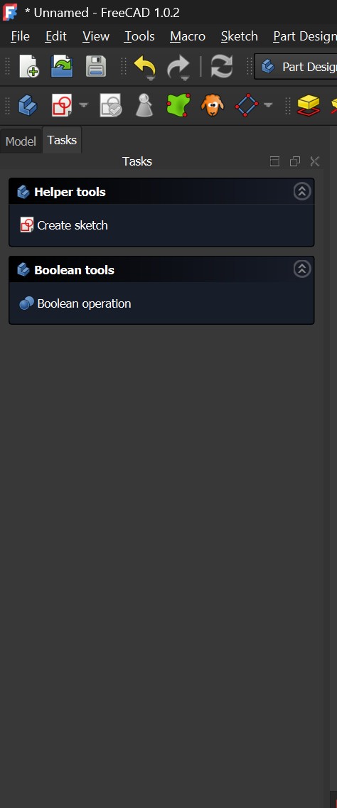
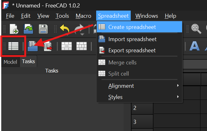
Tasks Toolbar (FreeCAD special feature-for me)
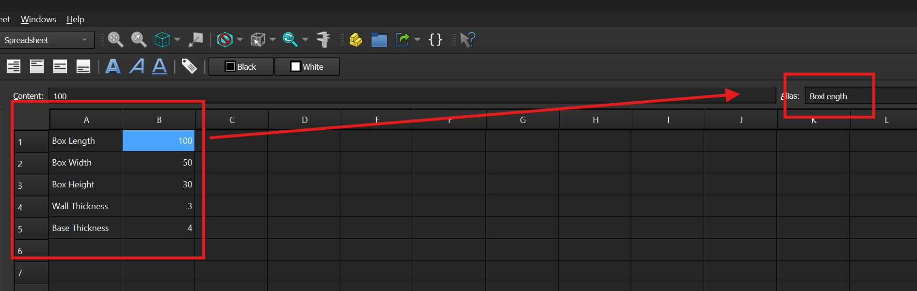
Defining Parameters
Defining Parameters
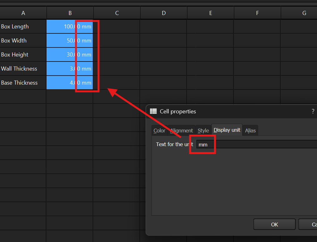
Defining Parameters units
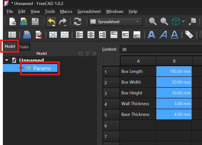
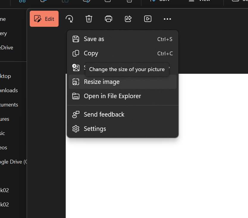
Where to find the parameters
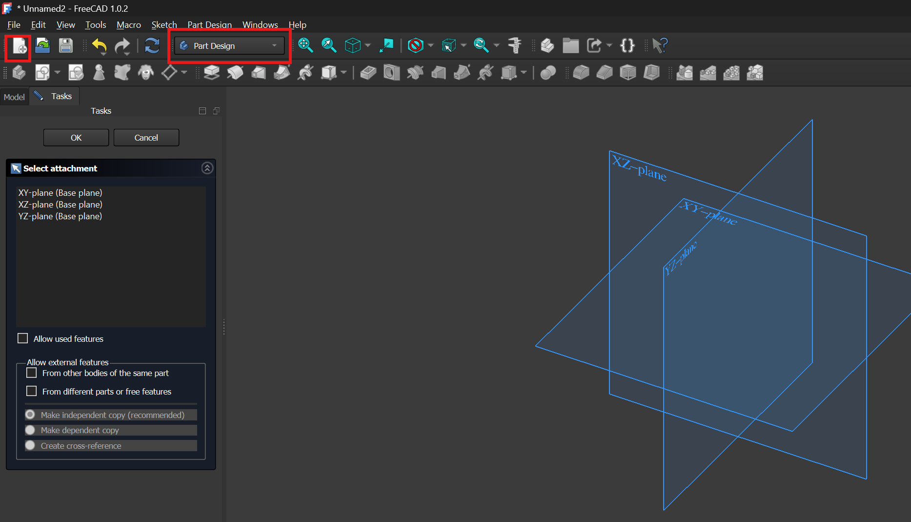
Selecting Part Design in FreeCAD
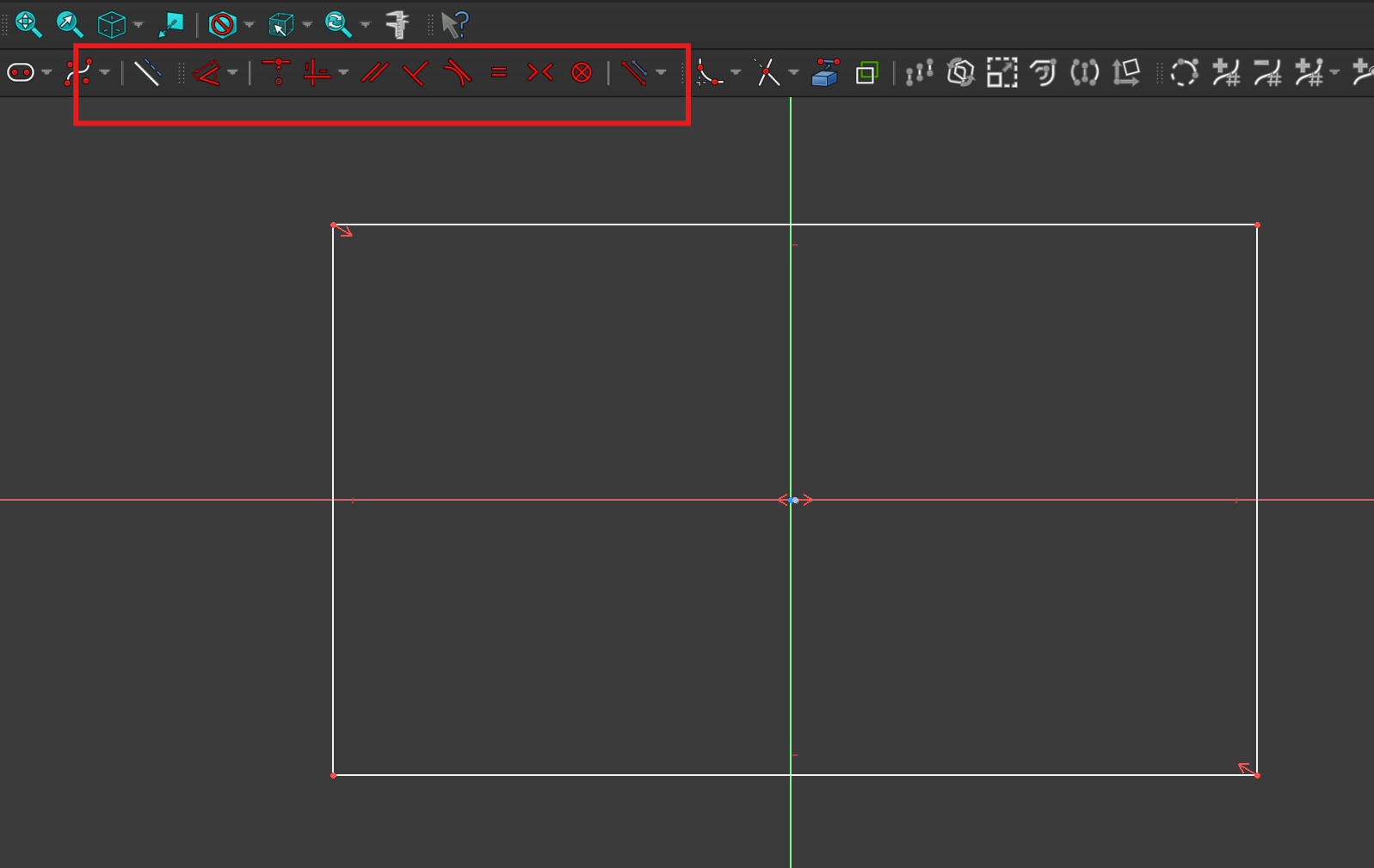
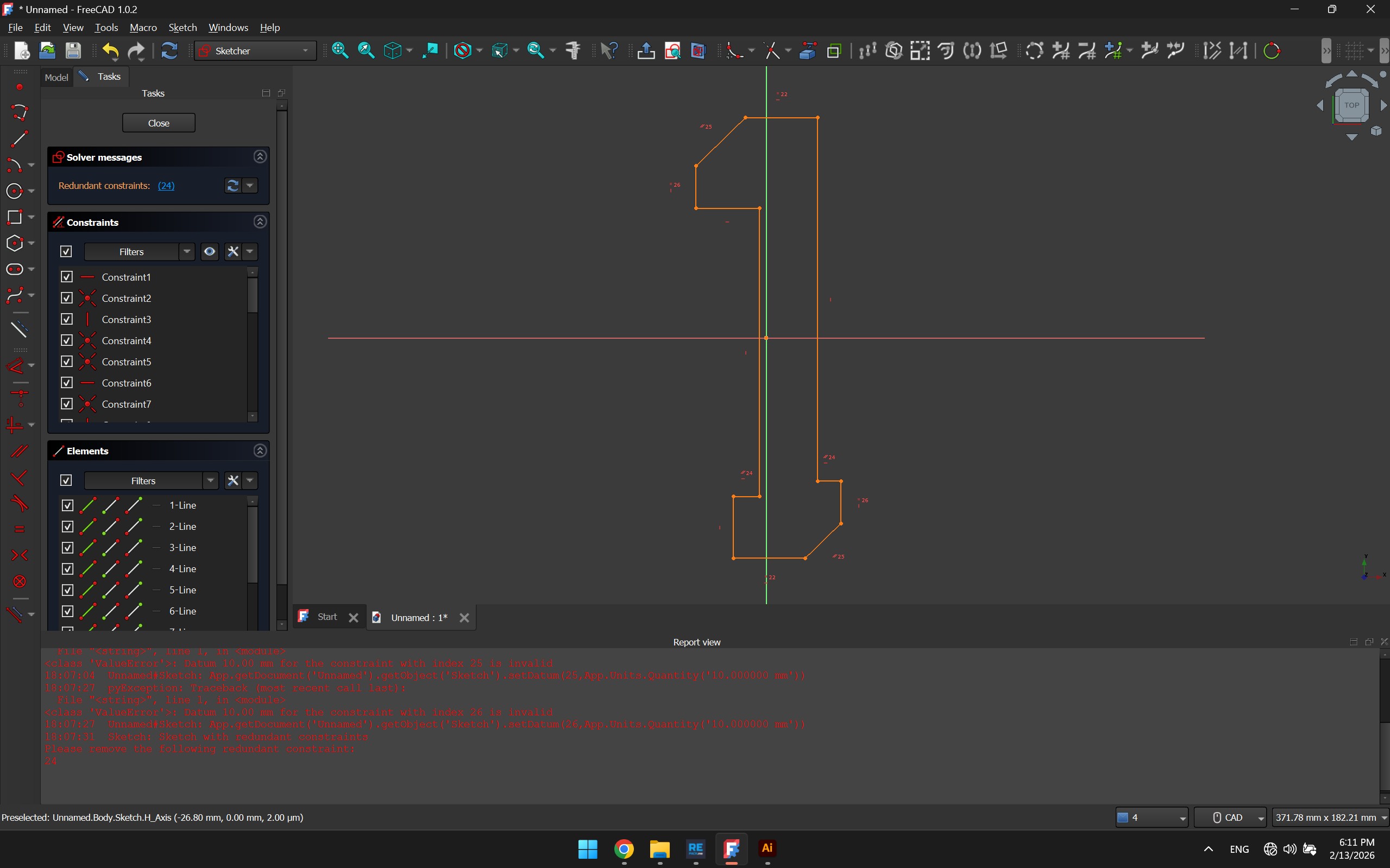
Sketch workspace and constraints
Browsing through the constraints
Exploring the expression editor to call the parameters defined - error
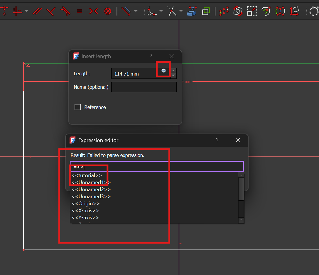
Exploring the expression editor to call the parameters defined-error
Exploring the expression editor to call the parameters defined - correct
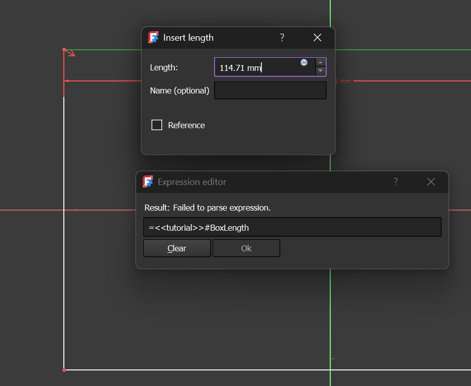
Exploring the expression editor to call the parameters defined-correct
Placing Constraints
Placing Constraints/div>
### Comparison: Parametric Workflows (FreeCAD vs. Fusion) While exploring parametric design, I compared how **FreeCAD** handles variables and constraints against **Fusion**. Though both achieve the same goal, the "philosophy" of the software is quite different: | Feature | **FreeCAD (Spreadsheet Workflow)** | **Autodesk Fusion** | | :--- | :--- | :--- | | **Logic Source** | **Spreadsheet-Driven:** You create a separate sheet and manually "alias" cells to turn them into variables. | **Global Parameters:** You use a built-in `fx` table that is integrated directly into the modeling environment. | | **Calling Variables** | **Specific Syntax:** You have to call the sheet name and the alias (e.g., `Spreadsheet.width`). It’s strict but very transparent. | **Direct Name:** You just type the name of the parameter (e.g., `width`) and it auto-completes. | | **Sketching Style** | **Solver-Strict:** Over-constraining a sketch immediately stops the solve. You have to manually find and delete the red constraints. | **Flexible Solver:** More "forgiving." It often warns you but allows more fluid movement until you're ready to fully define. | | **Interface** | **Task-Oriented:** You have to "Enter" and "Close" tasks (like the Sketcher or Spreadsheet) to move between steps. | **Modeless:** Most tools stay visible and accessible regardless of what mode you are in. | ### My Takeaway The biggest hurdle for me in FreeCAD was the **Expression Editor**. In Fusion, parameters feel like they are "just there," but in FreeCAD, you are essentially building a small database that talks to your 3D model. As you can see in my screenshots, I initially ran into errors because I wasn't using the correct syntax to call my spreadsheet values. Once I understood that I needed to reference the `Spreadsheet` object specifically, the parametric control became much more reliable. FreeCAD's workflow feels more manual, but it gives you a very clear map of exactly how your dimensions are linked.
## 2D Tools and Overview ### Adobe Illustrator & Inkscape Used for vector work. Illustrator remains the industry standard for my workflow, but Inkscape is a vital open-source alternative for FAB lab equipment compatibility. For this exercise I created the same logo on different software to compare how easy it is to use.
Switching between Inkscape and Illustrator was an exercise in muscle memory. While they both handle vectors, the "philosophy" of the software changes depending on whether you are designing for print or for a machine. | Feature | **Inkscape** | **Adobe Illustrator** | | :--- | :--- | :--- | | **Rectangle Tool** | Shortcut: **`R`** | Shortcut: **`M`** | | **Resizing (Proportions)** | Hold **`Ctrl`** while dragging. | Hold **`Shift`** while dragging. | | **Aligning Objects** | Relies on the **Align & Distribute** panel. | Highly automated with dynamic "Smart Guides". | | **Hairlines & Strokes** | Excellent for fabrication; allows for precise **0.001mm** stroke widths. | Can be tricky; often rounds numbers or requires specific profiles. | | **Machine Logic** | **Superior compatibility:** Exports clean SVG/DXF files. | Can be "bloated" with extra Adobe data. | ### My Observations Honestly, I found the Inkscape interface a bit less user-friendly overall. Illustrator feels more polished and fluid for quick design work, especially with how it handles alignment. However, where Inkscape lacks in "beauty," it makes up for in power. For digital fabrication, the **hairline stroke** options and the way it handles raw vector data make it much more reliable for talking to the machines. It’s less of a graphic design tool and more of a technical drawing tool—which is exactly what I need for precision work. Here is my result using Illustrator, and I realized its a better choice for me personally when it comes to designing vector graphics in comparison with Illustrator but I will use Inkscape for any postprocessing for file preparations.
Hero Shot
Another very popular tool for 2D design, and a personal favorite is AutoCAD! And after digging more into the 2D toolkit I have, I realized Inkscape is a great alternative to some AutoCAD pre-processing /file preparations which I used to do on AutoCAD in DXF format, such as CNC file preparations, a combination of both is even more powerful as the import > export relationship between them seems to be smooth...kind of. But to classify all the tools and the key differences in implementing a vector based approach heres a table! All three programs are **Vector-based**, meaning they use math to draw shapes. This allows you to zoom in forever without the image becoming "pixelated" (blurry). ### Comparison Table | Software | Core Logic | The "Easy" Explanation | | :--- | :--- | :--- | | **AutoCAD** | **Coordinates** | Uses absolute (x, y, z)$$coordinates. It focuses on geometric accuracy and dimensional constraints. | | **Illustrator** | **Bézier Curves** | Uses "handles" and "anchor points" to manipulate complex, organic curves through calculus. so kind of math based but focused. | | **Inkscape** | **SVG (Code)** | Uses XML-based code to define shapes. It is essentially a text file that a browser or machine reads as a drawing. | --- ### Understanding the Terms #### 1. Math-Based (Coordinates) In AutoCAD, If you tell the program to draw a circle with a radius of 10.005mm, it stores that exact numerical value. It is less about "art" and more about "geometry." This is why it’s the standard for manufacturing; the math translates directly to machine movements. #### 2. Bézier Curves This is the math used to create **smooth curves**. Instead of placing a thousand dots to make a circle, you place two points and pull on "handles." The math calculates the perfect curve between them. #### 3. SVG (Scalable Vector Graphics) While "Vector" is the category, **SVG** is a specific way to save that math. * **Inkscape** uses SVG as its main format. * **The Benefit:** Because SVG is written in a simple code language (XML), it is very "lightweight" and is the standard for web design and laser cutters. ### Summary * **Vector:** The overall technology (Math instead of Pixels). * **Bézier:** The mathematical tool used to make curves smooth. * **SVG:** A popular file format used to save and share vector math. A key quality of using vector graphics especially when exporting images is image quality control, in inkscape and illustrator I found the svg format for example the most ideal for web integrations as it preserves the size and quality of the graphics , example below:
Hero Shot
Pro Tip: Fix SVG Font Mismatches

To ensure your design looks the same on the web as it does in Inkscape, follow these steps:

Method How-To Result
Object to Path Path > Object to Path 100% visual accuracy; text is no longer editable.
Inline SVG Paste SVG code in HTML Text stays searchable and uses your site's CSS fonts.
Plain SVG Save As > Plain SVG Removes Inkscape-specific data for a cleaner file.

Warning: Always save a backup "editable" SVG before converting text to paths, as you cannot reverse this once the file is closed!

### Photoshop & Photopea I use Photopea as a strong browser-based backup for Photoshop. It allows me to edit rastered posters without needing a local installation. Raster images are pixel-based, resolution-dependent, and ideal for detailed photographs (e.g., JPEG, PNG), losing quality when scaled And software such as photoshop and photopea, exactly deal with that, Use raster graphics (pixels) when working with photographs, complex imagery, or detailed textures that require subtle color variations, shading, and high-resolution, photorealistic details. Raster is ideal for digital art, photo editing, and web graphics where specific pixel-based quality is needed, for example I took my personal image and desaturated it to create a raster poster, n my project, meaning the image is treated as a high-density grid of pixels, where each individual "square/pixel" stores a specific mix of Red, Green, and Blue (RGB) light. Understanding this is vital because raster images are resolution-dependent; if there aren't enough pixels per inch (PPI), the image becomes blurry or "pixelated" when enlarged. When I colored my photo for the poster, I used Photopea to balance these RGB channels equally and applied a blue filter over it, converting the color data into shades of blue using the screen overlay while preserving the fine textures and shading that only a pixel-based format can capture.
Pixels-blye Pixels-black
Pixels-blye
## Image and File Compression Techniques used ### Illustrator and Images I used the option Export for Web using the settings below (30% Quality/Medium/) Another Technique for unprocessed images/or no designs such as static photos I used the built in image viewer in windows to Edit the image and "Resize"
Save for Web Save for Web Resize image
### Videos I use Openshot Video Editor to export my videos to a desired size and quality using MP4 (h.264) Used settings:
Video Export Settings
## Results & Evaluation Reflecting on this week, the transition from purely commercial software to open-source alternatives like FreeCAD requires a mindset shift but I realized open source softwares are more engineered and include features designers found a workaround to integrate them into their daily flow works, but in a short summary I can say 2D tools extend beyond sketch and transponse between softwares, selecting the correct base 2D design file format can extend from design phase to manufacturing phase. As for 3D design tools, I came to a conclusion they're like programming languages, they're all powerful but the end user (me in this case) could simply feel more comfortable to work with just one from a product design perspective. ## Global Lecture Notes ### Key Takeaways - **Raster vs Vector:** Understanding when to use pixels vs mathematical paths. - **Parametric Design:** Designing with variables to allow for easy adjustments later in the project.

Resources & Assets