Group Assignment
## Power Consumption Analysis This week, we focused on measuring the power consumption of different output devices. Using a multimeter, we tracked the current draw for the OLED and the surge requirements for the solenoid. Full group documentation is available on our **[Lab Group Page](#)**.
## Introduction: Output Categories To translate system data into meaningful feedback, I explored three types of output devices—each targeting a different mode of interaction: visual, auditory, and kinetic. ### Visual Output – OLED Display An OLED screen is used to provide real-time data visualization. It allows the system to communicate sensor readings and system states clearly and continuously, making it the primary interface for monitoring. ### Auditory Output – Buzzer A buzzer is implemented for immediate alerts and notifications. Unlike the display, which requires active attention, the buzzer provides passive feedback, ensuring critical events are noticed even when the user is not directly observing the system. ### Kinetic Output – Solenoid A solenoid introduces physical actuation into the system. It converts electrical signals into mechanical motion, enabling tangible responses such as triggering a mechanism or simulating interaction with the physical environment. ### System Overview Together, these outputs form a multi-modal feedback system that enhances usability by engaging different human senses and enabling both informative and responsive interaction with the system.

## Visual Output: OLED (SSD1306) The OLED is my primary interface for project status. I used I2C to communicate between the microcontroller and the 0.96" display. ### OLED Screen test (isolated) The first issue I faced was troubleshooting if the OLED screen I have actually works or is there a problem with my PCB so I isolated the screen and did a breadboard test using Arduino UNO. It proved the screen was OK! and my main issue was the screen I purchased had the VCC and GND pins opposite to what I have used in my KiCAD footprint. ### Test Code:
oled_test.ino

                  #include <Wire.h>
                  #include <Adafruit_GFX.h>
                  #include <Adafruit_SSD1306.h>


                  #define SCREEN_WIDTH 128
                  #define SCREEN_HEIGHT 64
                  #define OLED_RESET    -1 
                  #define SCREEN_ADDRESS 0x3C // If it doesn't work, try 0x3D

                  // Initialize the display using the "Wire" I2C bus
                  Adafruit_SSD1306 display(SCREEN_WIDTH, SCREEN_HEIGHT, &Wire, OLED_RESET);

                  void setup() {
                    // 1. Setup Status LEDs (Active LOW on RP2040)
                    pinMode(17, OUTPUT); // Red
                    pinMode(16, OUTPUT); // Green
                    digitalWrite(17, HIGH); // Off
                    digitalWrite(16, HIGH); // Off

                    // 2. Define I2C Pins for XIAO RP2040 (D4 = SDA, D5 = SCL)
                    Wire.setSDA(6);
                    Wire.setSCL(7);
                    Wire.begin();
                    Wire.setClock(100000); // Set to 100kHz for stability

                    // 3. Try to initialize the OLED
                    if(!display.begin(SSD1306_SWITCHCAPVCC, SCREEN_ADDRESS)) {
                      digitalWrite(17, LOW); // Turn on RED if failed
                      while(true); // Stop here
                    }

                    // 4. Success! Turn on Green LED
                    digitalWrite(16, LOW); 

                    // 5. Show something on the screen
                    display.clearDisplay();
                    display.setTextSize(2);
                    display.setTextColor(SSD1306_WHITE);
                    display.setCursor(10, 20);
                    display.println(F("RP2040 OK"));
                    display.display();
                  }

                  void loop() {
                    // Just stay alive
                  }
            
Hero Shot OLED is OK
### Individual Assignment: Playstation on a budget For the assignment and following up on [Week 09](week09.html) , I decided to visualize the sensor input (potentiometer) and play around the idea of tracing a graph , as my [Final Project](final-project.html), will need to plot differnt curves according to its to be digital contour guage sensors, this all led me to get a low version of flybird - Input : Potentiometer - Microcontroller : RP2040 - Output : 4 Pin OLED

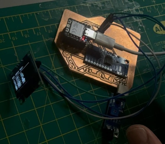
No input detected test, then a flybird inspired test run !

### Code:
game-test.ino

                  #include <Wire.h>
                  #include <Adafruit_GFX.h>
                  #include <Adafruit_SSD1306.h>

                  #define SCREEN_WIDTH 128
                  #define SCREEN_HEIGHT 64
                  #define SCREEN_ADDRESS 0x3C

                  // --- MUX & PINS ---
                  const int S0 = 0; const int S1 = 1; const int S2 = 2; const int S3 = 3;
                  const int SIG_PIN = 26; 

                  Adafruit_SSD1306 display(SCREEN_WIDTH, SCREEN_HEIGHT, &Wire, -1);

                  // --- GAME VARIABLES ---
                  float playerY = 32;
                  float smoothedInput = 512;
                  float alpha = 0.2; // Mario-smoothness factor
                  int wallX = 128;
                  int gapY = 32;
                  int score = 0;
                  bool gameOver = false;

                  void setup() {
                    Wire.setSDA(6); Wire.setSCL(7); Wire.begin();
                    pinMode(S0, OUTPUT); pinMode(S1, OUTPUT);
                    pinMode(S2, OUTPUT); pinMode(S3, OUTPUT);
                    
                    if(!display.begin(SSD1306_SWITCHCAPVCC, SCREEN_ADDRESS)) for(;;);
                    display.clearDisplay();
                  }

                  void resetGame() {
                    wallX = 128;
                    score = 0;
                    gameOver = false;
                    gapY = random(10, 50);
                  }

                  void loop() {
                    if (gameOver) {
                      display.clearDisplay();
                      display.setTextSize(2);
                      display.setCursor(10, 20);
                      display.println("GAME OVER");
                      display.setTextSize(1);
                      display.setCursor(30, 45);
                      display.print("Score: "); display.println(score);
                      display.display();
                      
                      // To restart: Turn the pot all the way down and back up
                      int r = analogRead(SIG_PIN);
                      if (r < 50) resetGame();
                      return;
                    }

                    // 1. SELECT J1 & READ
                    digitalWrite(S0, LOW); digitalWrite(S1, LOW);
                    digitalWrite(S2, LOW); digitalWrite(S3, LOW);
                    int raw = analogRead(SIG_PIN);

                    // 2. SMOOTH MOVEMENT (Mario Physics)
                    smoothedInput = (alpha * raw) + ((1.0 - alpha) * smoothedInput);
                    playerY = map((int)smoothedInput, 0, 1023, SCREEN_HEIGHT - 5, 5);

                    // 3. MOVE WALLS
                    wallX -= 3; // Game speed
                    if (wallX < -10) {
                      wallX = 128;
                      gapY = random(10, 45); // Randomize the next gap
                      score++;
                    }

                    // 4. COLLISION DETECTION
                    // Check if player (X=20) hits the wall (wallX) outside the gap (gapY)
                    if (wallX > 15 && wallX < 25) {
                      if (playerY < gapY - 8 || playerY > gapY + 8) {
                        gameOver = true;
                      }
                    }

                    // 5. DRAWING
                    display.clearDisplay();

                    // Draw Player (Mario/Square)
                    display.fillRect(20, (int)playerY - 2, 5, 5, SSD1306_WHITE);

                    // Draw Walls (with a gap)
                    display.drawFastVLine(wallX, 0, gapY - 10, SSD1306_WHITE); // Top wall
                    display.drawFastVLine(wallX, gapY + 10, SCREEN_HEIGHT, SSD1306_WHITE); // Bottom wall

                    // Score
                    display.setTextSize(1);
                    display.setCursor(0,0);
                    display.print("Score: "); display.print(score);

                    display.display();
                    delay(20);
                  }
            
### Code Breakdown | Code | Function | Description | | :--- | :--- | :--- | | **`setup()`** | **Hardware Handshake** | Initializes I2C communication on specific pins (6 & 7) and sets the MUX control pins to `OUTPUT` mode. | | **`setup()` Array Fill** | **Canvas Prep** | Uses a `for` loop to fill the `history` array with the bottom screen coordinate so the graph starts clean. | | **MUX Selection** | **Input Routing** | Manually sets `S0-S3` to `LOW` to "open the gate" for channel **J1** on the multiplexer. | | **`analogRead()`** | **Data Acquisition** | Grabs the raw voltage (0-1023) from the multiplexer's signal pin. | | **EMA Smoothing** | **Noise Filtering** | Uses the `alpha` weight to blend the new reading with the previous one, creating a "weighted" average. | | **Timing Logic** | **Pacing** | Checks if 39ms have passed using `millis()` to ensure the graph scrolls at a steady human-readable speed. | | **History Shift** | **Scrolling Effect** | A `for` loop that bumps every data point one pixel to the left to make room for the latest reading. | | **`map()` Function** | **Translation** | Rescales the 0-1023 sensor data into 64-15 pixel coordinates (inverted so high values go "up"). | | **`drawLine()`** | **Vector Rendering** | Connects the dots between `history[i]` and `history[i+1]` to create a continuous waveform. | | **`display.display()`** | **Buffer Push** | Sends the completed drawing commands from the Arduino's RAM to the physical OLED screen. |
## 2. Auditory Output: Piezo Buzzer The buzzer is used to provide feedback for user interactions or system alerts.
buzzer_test.ino

         documentation in progress - PCB damaged and still waiting to make new one
            
## 3. Mechanical Output: Solenoid For the mechanical expansion of the mannequin project, the solenoid provides the necessary linear force. I used a MOSFET to safely drive the high-current load. documentation in progress - PCB damaged and still waiting to make new one

Resources & Assets