## Wild Card Indeed. In this week I explored something completely unrelated to the past few weeks were I was focused on Electronics and Additive manufacturing techniques for my final project, In this Week I satisfied a curiosity to work with a Robotic machine, which I have long wanted to at least understand the most fundamental concepts and operations, A special thanks goes to my instructor **Naim Al-Haj Ali** who has truly shed some light on this topic , which through my experience, I never tapped into. ## Introduction to Robotics Robotic arms are advanced automated fabrication systems capable of executing precise and repeatable movements across multiple axes. Unlike conventional CNC machines that rely on fixed linear motion, robotic arms offer greater spatial freedom, enabling complex toolpaths and adaptive fabrication processes. They are widely used in manufacturing, robotic milling, additive manufacturing, assembly, and experimental digital fabrication, while supporting a variety of end effectors including milling spindles, extruders, grippers, scanners, and custom fabrication tools depending on the intended workflow and material system.
## Introduction to KUKA KR 70 R2100 / SEL For this week, we explored the fundamentals of robotic fabrication through the **KUKA KR 70 R2100 / SEL** from the **KUKA IONTEC Series** (the robotic arm available in our lab). The robot features a payload capacity of 70 kg and a reach of 2100 mm, allowing it to operate within a large working envelope while carrying heavy fabrication tools with high precision and rigidity. Throughout the process, we focused on understanding the robot’s kinematics, coordinate systems, tool center point (TCP), safety procedures, and basic operational workflows. The exploration also introduced the relationship between computational design and robotic control through digital toolpath generation and robotic motion planning. The KUKA KR 70 R2100 / SEL is a versatile robotic fabrication platform capable of applications such as robotic milling, large scale additive manufacturing, pick and place operations, scanning, and experimental material fabrication. Operating through **6 axes of movement** that simulate the motion of a human arm through base rotation, shoulder movement, elbow movement, and wrist articulation, the robot achieves high flexibility and precision within three-dimensional space, enabling complex positions and tool orientations required for advanced fabrication workflows. Through this introduction, the robot was approached not only as an industrial machine, but as an adaptive fabrication system capable of bridging digital design, material experimentation, and advanced manufacturing processes. ![KuKA Overview](../images/week16/0.jpg) *Figure 1: Robotic arm cell deployment overview within the workspace.*
KUKA Working Envelope
Tracking View A: Workspace reach envelope boundaries.
Mounting Flange
Mounting Flange
Foundational Framework: KUKA System Architecture & Safety

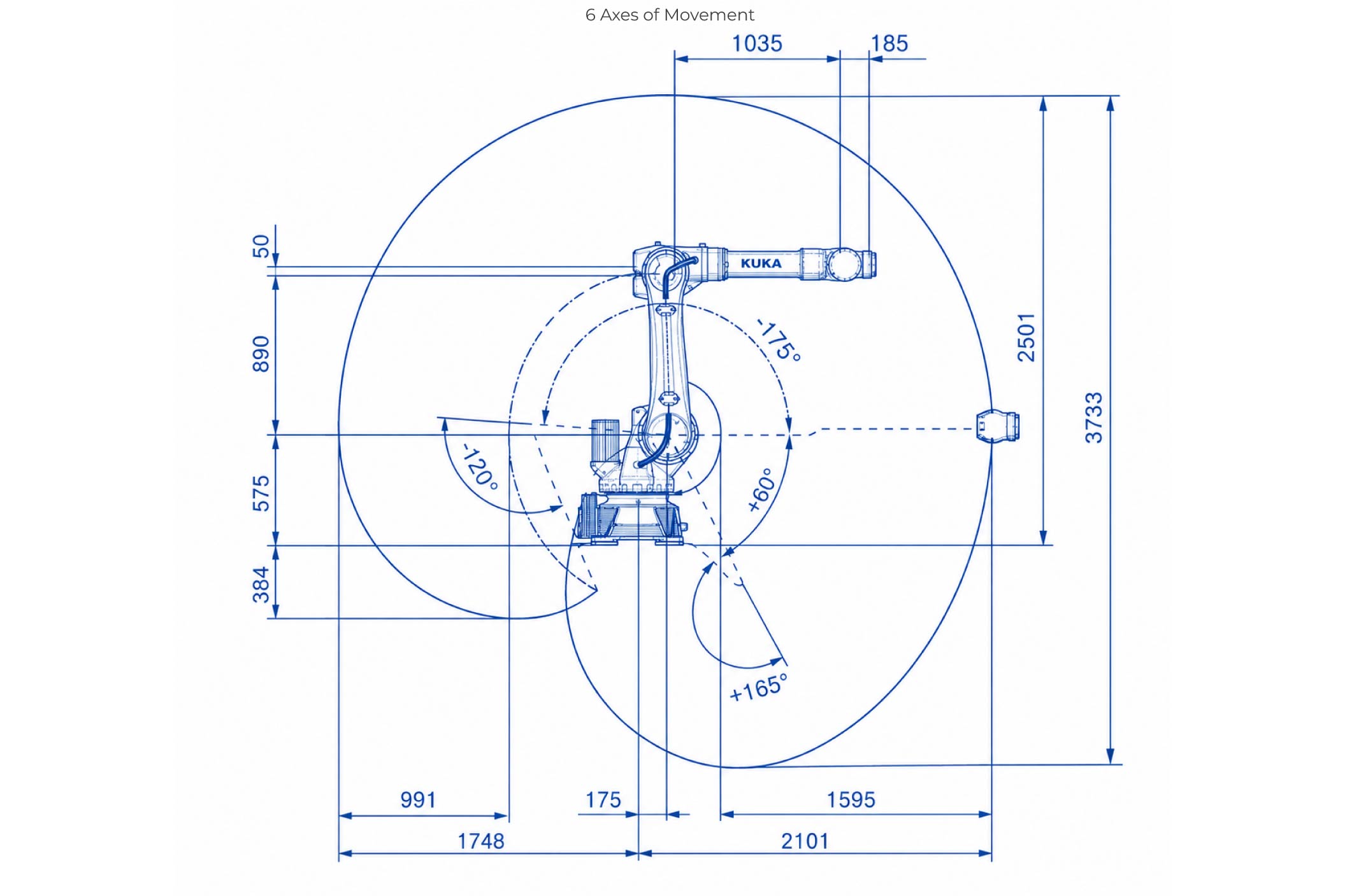
System Capability: The KUKA robotic arm operates as a high-precision, 6-axis articulation platform engineered for advanced manufacturing and digital fabrication. Mastering its core sub-assemblies and interface logic is necessary to maintain a safe, highly repeatable production workflow.

The smartPAD Teach Pendant: This handheld terminal serves as the primary control interface for configuration and manual programming. Using its tactile buttons, directional joysticks, and graphic display panel, you can manually jog separate axis nodes, generate programmatic motion paths, and monitor realtime joint diagnostics.

Safety Protocol Infrastructure: Due to the heavy payload momentum of industrial automation, rigid safety workflows are mandatory. Standard operating safety constraints include:

  • Physical Boundaries: Enforcing interlocking safety cages or light-curtain barriers to isolate the arm's active reach envelope during automated execution.
  • Risk Mitigation: Conducting pre-flight structural inspections and tracking coordinate clearing bounds to preempt mechanical collisions.
  • Emergency Systems: Verifying hardware E-Stop circuits and maintaining clear pathways to quick-shutdown triggers before applying motor power.
### About the IONTEC Series The KUKA IONTEC family represents a newer generation system optimized for flexible industrial automation, featuring: - **High Rigidity:** Engineered to reduce structural deflection under structural cutting strains. - **High Precision:** Maintains ultra-tight tolerances across complex industrial paths. #### Primary Application Domains: - Robotic Milling & Subtractive Fabrication - Large-Scale Additive Manufacturing - Friction Stir Welding & Assembly Workflows - Machine Tending & Pick-and-Place Automation
## Software Automation ### Rhino and Grasshopper Integration Computational design workflows bridge directly into robotic kinematics using dedicated programming environments. Parametric logic curves generated inside Grasshopper are translated dynamically into explicit coordinate sets to drive multi-axis motion paths. ### Step-by-Step KUKA prc Drawing Workflow Below is the streamlined procedure used to convert line drawings into automated machine code script sequences using Grasshopper and the KUKA prc plugin interface.
Preparation and Curve Setup
Step 1: Workspace Setup
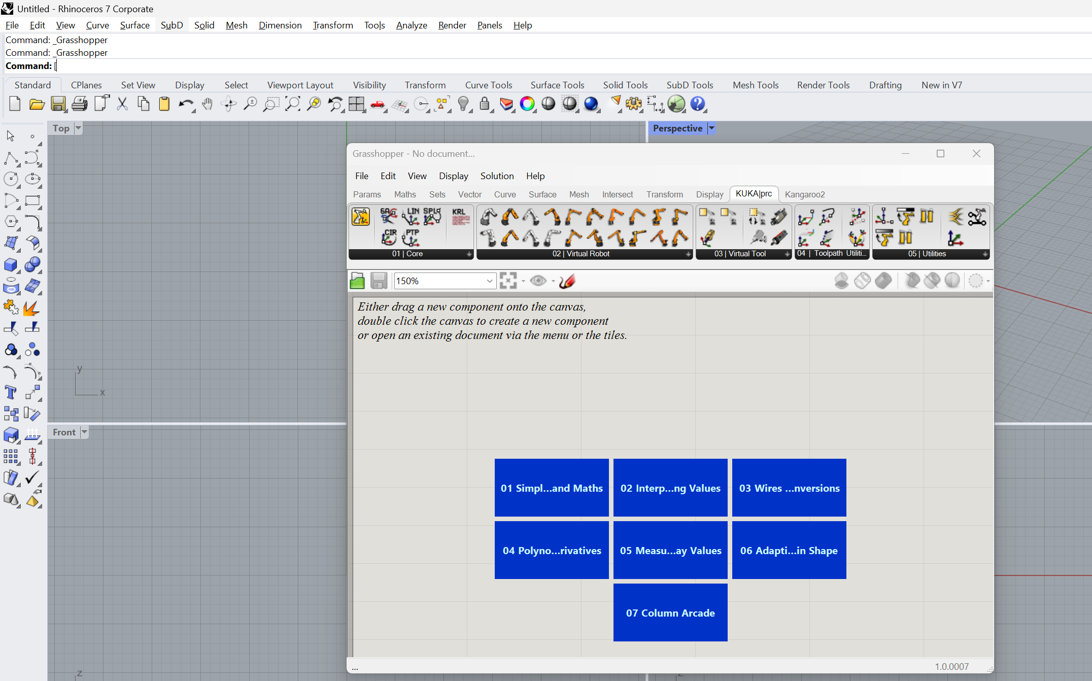
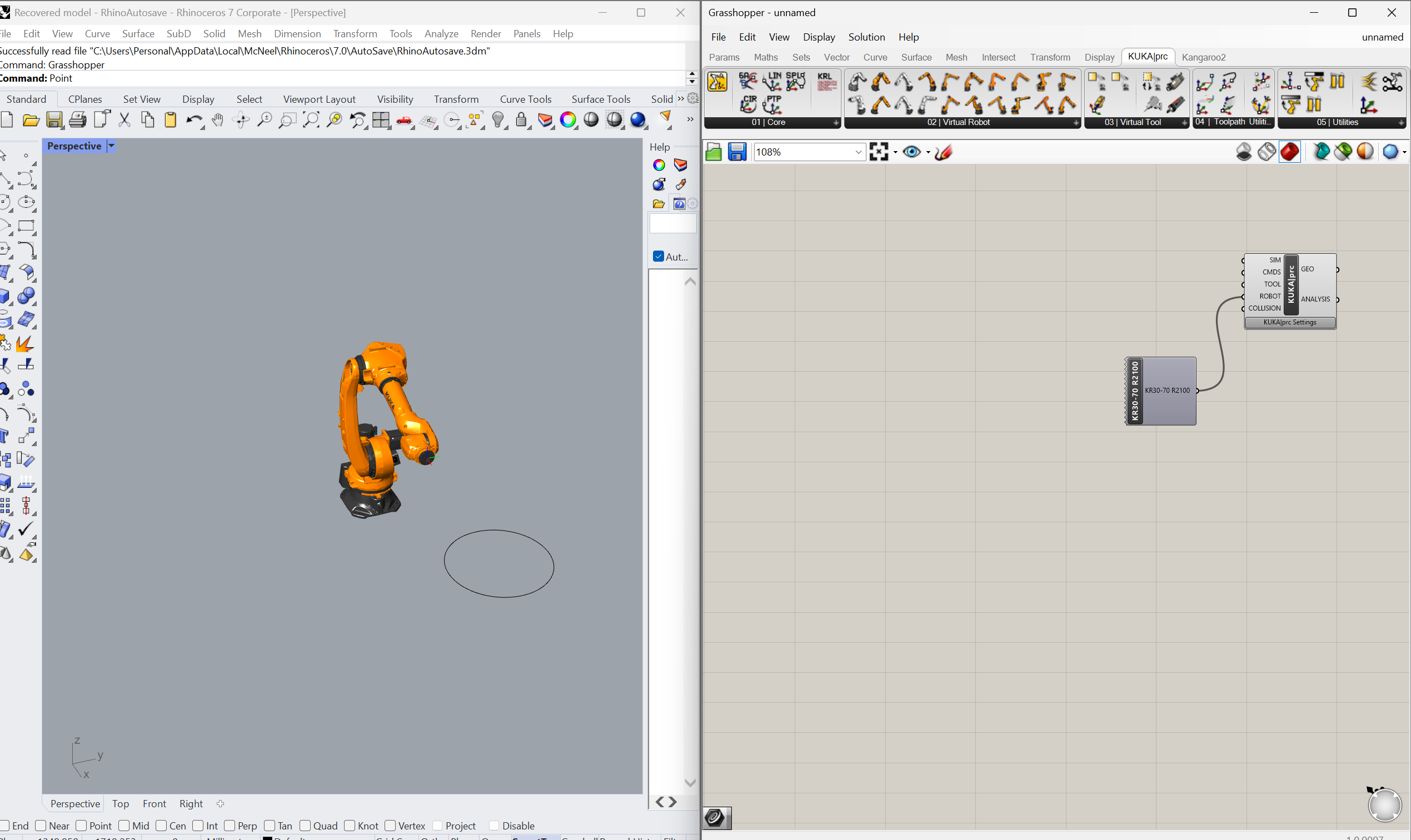
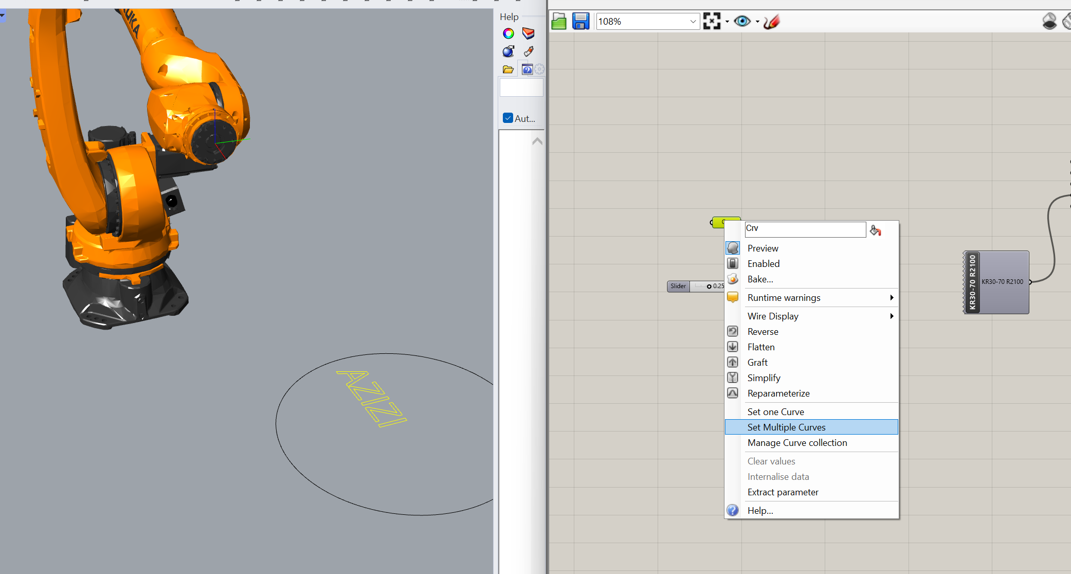
Open a clean model space, hide environmental cell fixtures, and reference target line drawings into a Curve container block.
Convert to Polylines
Step 2: Polyline Discretization
Pass vector geometry into 'Curve to Polyline' (Curve > Util). Link a number slider to match desired tracking accuracy tolerances.
Generate Control Points
Step 3: Vertex Extraction
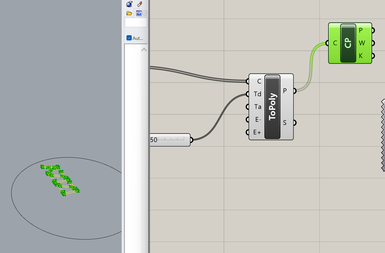
Drop a 'Control Points' analytical component (Curve > Analysis) onto the canvas to map out explicit coordinates along the split lines.
Establish Cartesian Directions
Step 4: Vector Plane Mapping
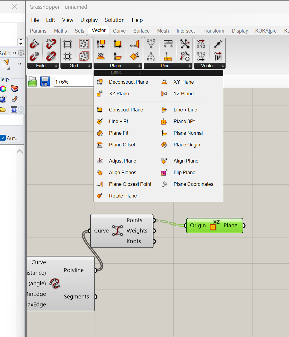
Construct local XY planes at each control vertex (Vector > Plane) to dictate the exact physical approach orientation for the arm.
Setup Robot Movement
Step 5: KUKA prc Engine Docking
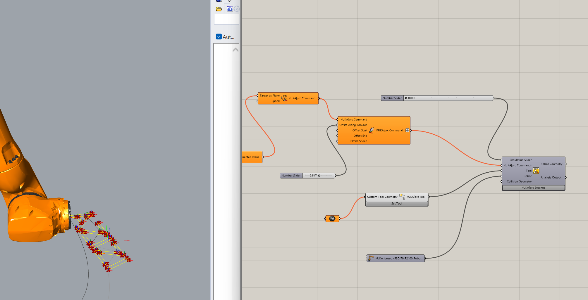
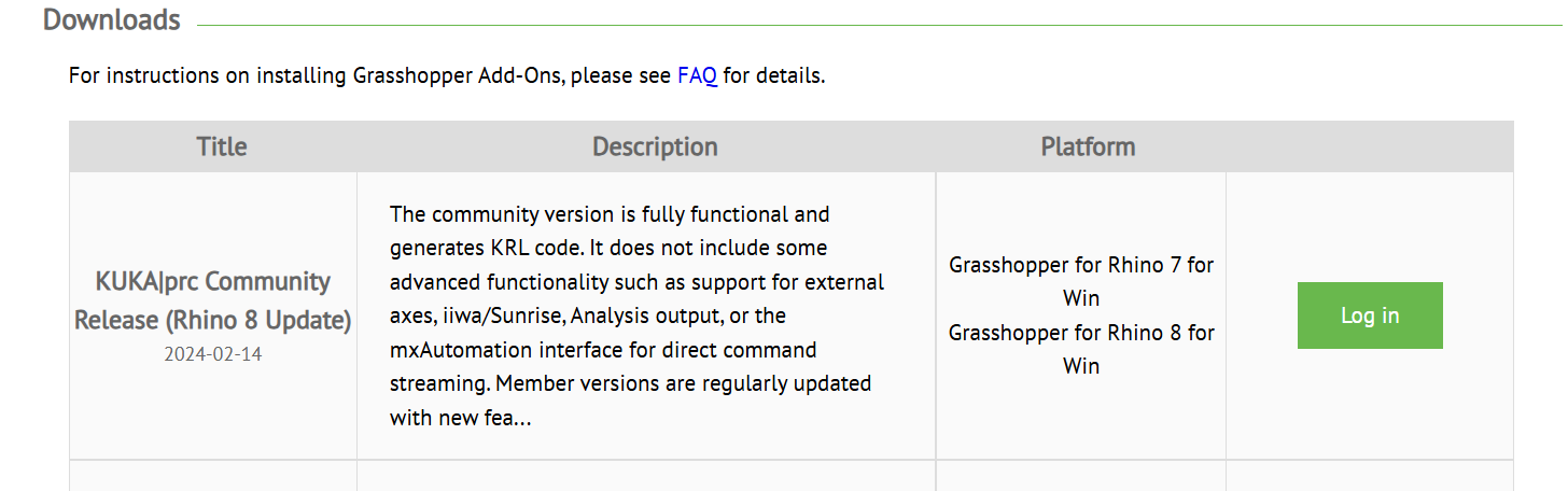
Bring in the native KUKA prc core components and stream the vector planes directly into the motion inputs.
Adjust Tool Offset
Step 6: Offset Tool Length
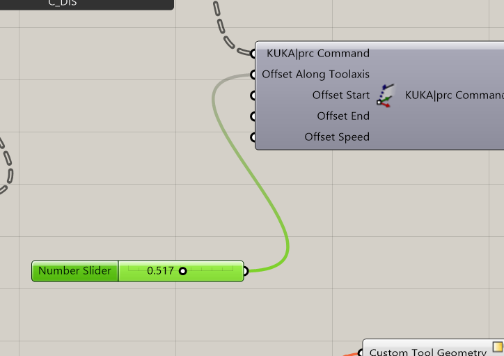
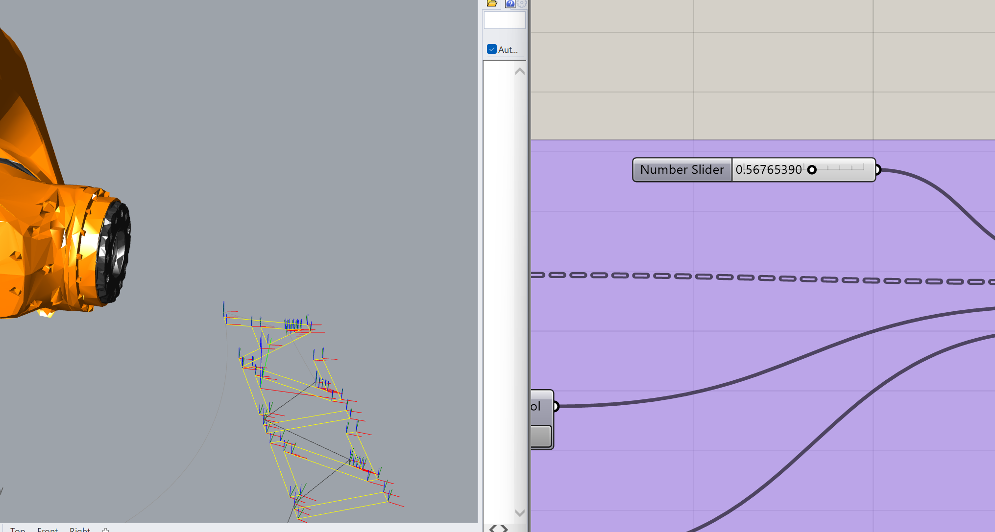
Introduce a 'Tool Axis Offset' block paired with a number slider to calibrate drawing pressure at the physical writing tip.
Simulate Robot Movement
Step 9: Dry Run Simulation
Trigger the KUKA prc play module to perform a collision check, verifying toolpaths clear all physical laboratory table bounds.
### Parametric Toolpath Generation via KUKA prc To translate digital curves into physical movements, I structured a computational workflow using Rhino, Grasshopper, and the **KUKA prc** parametric plugin. This setup systematically converts static vector geometric lines into machine-readable robotic toolpaths. #### 1. Environmental Geometry Setup & Curve Import * **Cell Preparation:** Opened a clean model instance in Rhino. While spatial reference elements—such as the physical workbench and safety cell enclosures—were modeled to prevent real-world collisions, they were safely hidden to clear the active modeling canvas. * **Pipeline Sourcing:** Launched Grasshopper and referenced the vector artwork from Rhino into a `Curve` container component. Selecting the target paths sequentially inside the viewport binds the raw geometry directly to the parametric canvas. #### 2. Discretization & Vector Analysis * **Polyline Conversion:** To ensure the 6-axis controller handles the paths cleanly, complex curves were discretized into multi-segment polylines using **Curve → Util → Curve to Polyline**. An analytical number slider was paired here to adjust tolerance thresholds dynamically, keeping point spacing tight without causing data bloating. * **Control Point Extraction:** Fed the polyline output into a **Curve Analysis → Control Points** block. This extracts the exact vertex coordinates required to chart the robot's progressive travel nodes. #### 3. Plane Orientation & Kinematic Mapping * **Local Coordinate Framing:** Generated custom tracking frames at each vertex using **Vector → Plane**. This maps an operational XY plane natively to every coordinate point, defining explicit local Cartesian directions for the tool head approach. * **Core Kinematic Integration:** Dropped the primary **KUKA prc** movement block onto the canvas and piped the tracking planes directly into its command inputs to establish spatial position vectors. #### 4. End Effector Offsets & Command Compilation * **Tool Axis Correction:** Wired in a `KUKA prc Tool Axis Offset` component to configure the precise stance width distance between the physical flange and the writing tip. The offset depth is managed dynamically via a dedicated number slider to guarantee perfect drawing pressure. * **Controller Parsing:** Integrated a centralized KUKA Robot Controller node. This block acts as the main compiler, translating the high-level Grasshopper component stack directly into native, production-ready **KRL (KUKA Robot Language)** script arrays. #### 5. Volumetric Visualization & Path Simulation * **Mesh Reference:** Brought in the custom 3D mesh data of the physical end effector (the pen holder assembly) through a `Mesh` component, docking it straight to the tool visualization input parameter. * **Orientation Optimization:** Refined the static position boundaries and structural rotation coefficients of the tool attachment to ensure the physical pen remains perfectly perpendicular against the structural tracking surface. * **Pre-Flight Digital Dry Run:** Engaged the built-in KUKA prc play module to run a comprehensive kinematic simulation loop. This testing routine verifies overall motion fluidity, evaluates reach bounds, and confirms that the final tool orientation avoids collision pathways with structural fixtures or laboratory tables.
## Calibration Protocol
3-Point Base Framework Calibration Routine
4-Point Base Framework Calibration Routine
Methodology Selection: Base vs. TCP Calibration

3-Point Calibration = Base Frame Setup: Use this to define your physical workspace coordinates (like mapping a table, fixture, or material block). It establishes the local origin, X-axis, and Y-axis directions.

4-Point Calibration = Tool Center Point (TCP) Setup: Use this exclusively to teach the robot the exact physical tip of your end effector. By touching a single reference spike from four different angles, the system calculates the tool's length and physical offset.

Critical Safety Warning

Always verify the Tool Center Point (TCP) data and execute low-speed dry runs ($10\%$ axis speed maximum) to prevent geometric collisions during automated travel cycles.

### Executing the XYZ 4-Point Tool Calibration To track the precise position of our end effector relative to the arm's mounting flange, I ran an XYZ 4-Point Calibration sequence on the KUKA smartPAD teach pendant using the following workflow: 1. **Switch to Expert Mode:** Changed the user group on the teach pendant to **Expert** mode to gain access to the system's advanced calibration tools. 2. **Locate Calibration Tools:** Opened the specialized **Tools** menu within the smartPAD interface. 3. **Select the XYZ 4-Point Method:** Chose the option to add a new tool, clicked **Calibrate**, and selected the **XYZ 4-Point** calculation method. 4. **Jog to Reference Points:** Manually jogged the robot to touch a fixed reference point in our lab cell four separate times. For each point, I approached the reference from radically different angles and joint configurations to give the software a comprehensive dataset. 5. **Automated Calculation:** Once the fourth point was captured, the calibration software automatically computed the geometric transformation and rotation matrices, accurately locking in our new Tool Center Point (TCP). --- ### KUKA IONTEC Equipment Specifications Datasheet | Technical Parameter | Metric Specifications | Industrial Performance Bounds | |:---|:---|:---| | **Series** | IONTEC Platform | Flexible Automation Class | | **Payload Capacity** | 70 kg | Heavy Tooling Load Rating | | **Maximum Reach** | 2101 mm | Extended Axis Envelope Span | | **Total Mass Weight** | 546 kg | Rigid Structural Cast Footprint | | **Production Date** | 2022-02 | Newer Generation Assembly | | **Origin Status** | Made in Germany | Precision Component Engineering |
## Operational Workflow We loaded the generated programs from rhino (KRL) files into the Teaching Pendant as shown in the videos, after checking the simulation. We then proceeded to try out different drawings and settings.
Operational Workflow
Results
Results

Resources & Assets