Focused on multi-sensor testing, signals, and data visualization.
Group Assignment
## Group Assignment
-Probe an input device(s)'s analog levels and digital signals (As a minimum, you should demonstrate the use of a multimeter and an oscilloscope.)
-Document your work on the group work page and reflect on your individual page what you learned
Full group documentation can be found on our **[Lab Group Page](https://fabacademy.org/2026/labs/techworks/week9/week9.html)**.
## Introduction: The Input Ecosystem
Input devices allow microcontrollers to interact with physical reality. For this week's assignment, I explored several categories of sensors defined by their operating principles:
* **Buttons & Switches:** Simple mechanical gates that complete a circuit.
* **Capacitive:** Measuring proximity through electrostatic field variance.
* **Resistive:** Physical force, light, or rotation changing resistance (Potentiometers, LDRs).
* **Magnetic:** Using Hall Effect sensors to detect magnetic flux.
* **Piezoelectric:** Materials generating voltage from mechanical stress or vibration.
### Data Transmission Protocols
* **GPIO (General Purpose I/O):** Binary digital triggers (High/Low).
* **GPIO + ADC:** Converting varying analog voltages into digital 10-bit values (0-1023).
* **I2C & SPI:** Serial communication for high-speed, complex sensor data like accelerometers.
* **Shift Registers:** Serial-to-parallel components used for expanding input capacity.
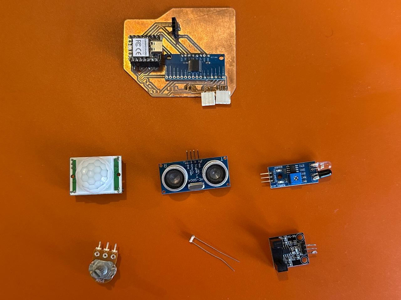
## Used Sensors Anatomy
I used the PCB I made in **Week 8** with **3-pin input headers** (VCC, GND, Signal). Here is the technical breakdown and pin-out explanation for my inventory:
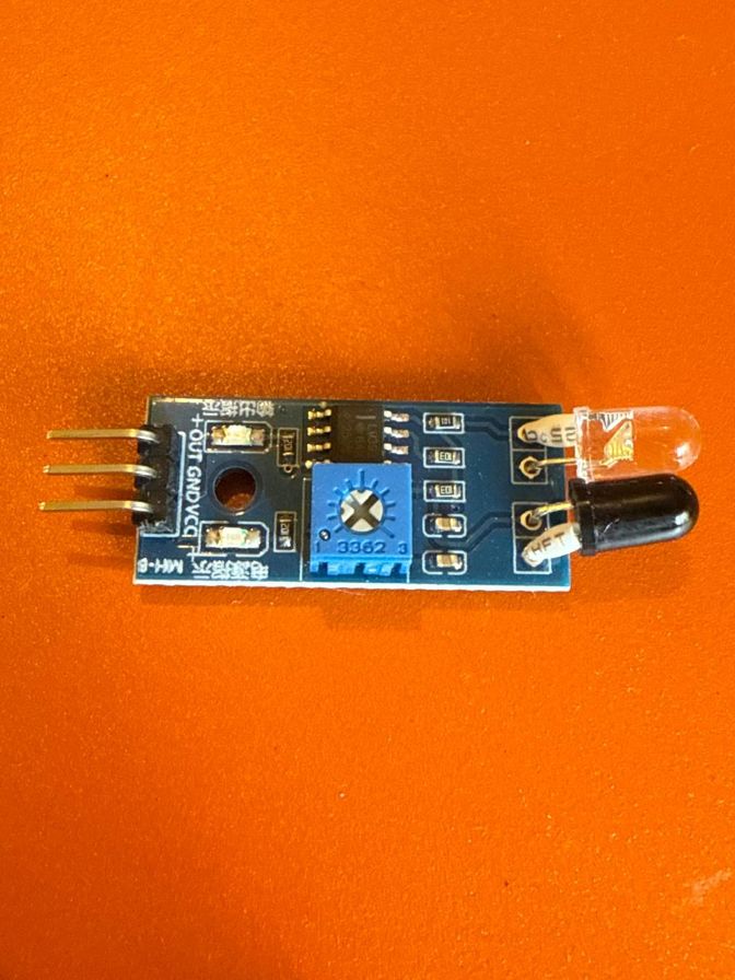
### Obstacle Sensor (IR Reflective)
Uses an IR LED transmitter and a photodiode receiver.
* **Pins (3 Total):** VCC (3.3V), GND, OUT (Digital).
* **Mechanism:** When an object reflects IR light back, the receiver detects it and sends a LOW signal.
* **Connection:** Used jumper wires to connect the sensor to the input port
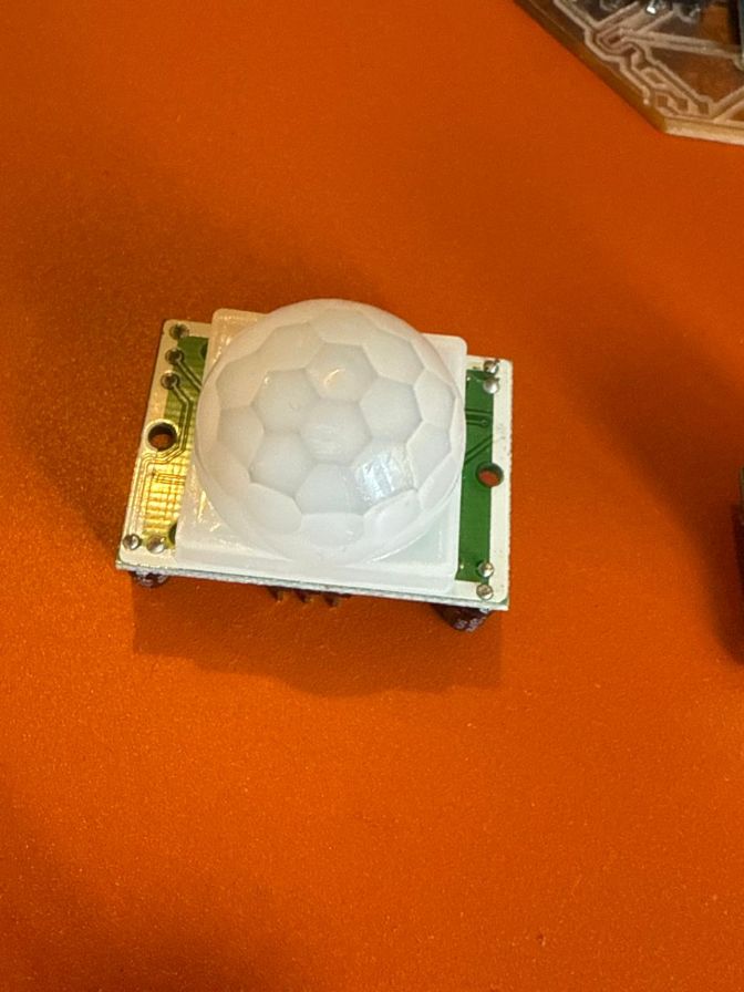
### PIR Motion Sensor
A Pyroelectric sensor that measures infrared heat signatures in motion.
* **Pins (3-4 Total):** VCC, OUT, GND.
* **Mechanism:** The white Fresnel lens (the globe) focuses IR radiation. When motion is detected, the OUT pin toggles HIGH.
* **Connection:** Adapted to the 3-pin layout.
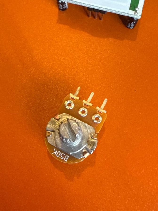
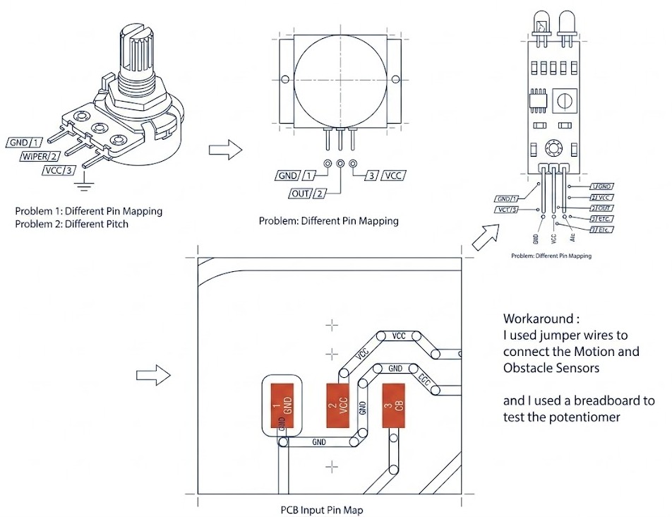
### Potentiometer
A mechanical rotary variable resistor.
* **Pins (3 Total):** Leg 1 (VCC), Leg 2 (Wiper/Signal), Leg 3 (GND).
* **Mechanism:** Turning the dial moves the wiper along a resistive track, providing a linear voltage sweep.
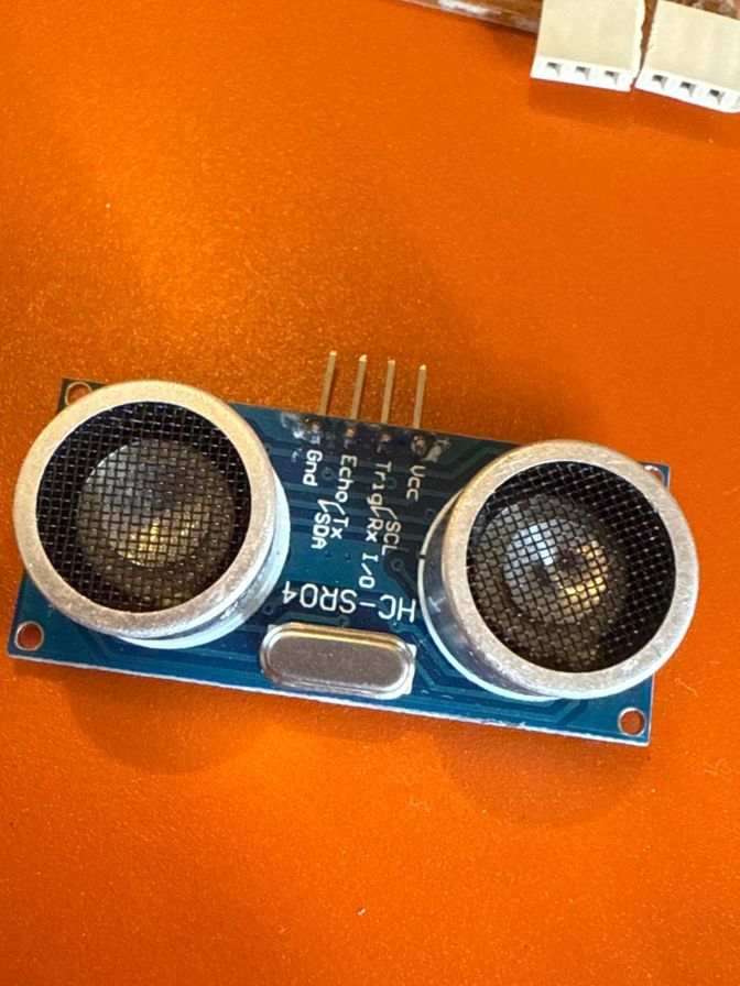
3 pin Sensors + the Ultrasonic Sensor (4pin)
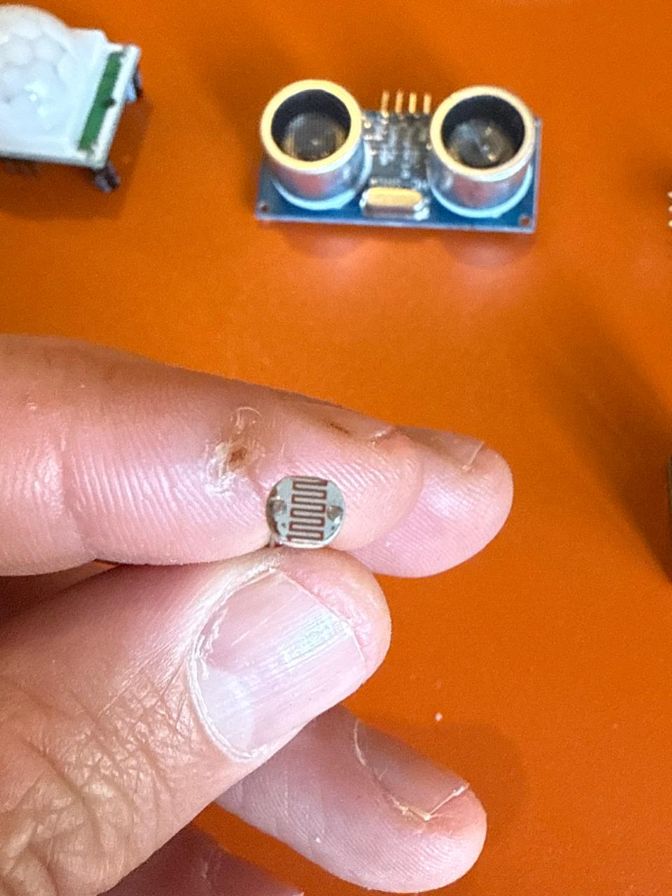
2 Pin LDR Sensor
50K Potentiometer
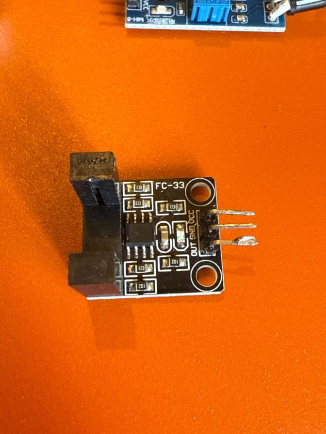
Speed Sensor
Obstacle Sensor
Ultrasonic Sensor
Motion Sensor
## 2. Sensor Family Classification
| Sensor | Operating Principle | Family | Signal Category |
| :--- | :--- | :--- | :--- |
| **PIR (Globe)** | Heat detection | Pyroelectric | **Digital** |
| **FC-33 (Horns)** | Beam interruption | Optical | **Digital** |
| **Ultrasonic** | Echo timing | Acoustic | **Digital** |
| **IR Obstacle** | IR Reflection | Optical | **Digital** |
| **Potentiometer** | Resistive track | Electromechanical | **Analog** |
| **LDR Sensor** | Photo-resistive | Photo-conductive | **Analog** |
| **Tactile Switch** | Circuit closure | Mechanical | **Digital** |
## Individual Assignment & Test Scripts
I tested each sensor separately on the PCB J1 Connection port [refer to Week06](week-six.html) for pin connection diagrams.
I had to use jumper wires to connect the pins to the PCB relative location, but it was a good exercise to refine my final project PCB.
## Troubleshooting
The first issue I faced was I completely mixed up mounting my RP2040 opposite to the schematic as when I did a 3D model
visualization of the PCB in week 08, my brain got locked to the model where I mistakenly placed the 3d block opposite to its correct location
meaning the Type C port was inverted in the 3D shot...
The second issue was my PCB although equipped with 3 pin PCB outlets for potential inputs, my PCB was in this order
Although for this week the workaround was using jumper wires and mediators, a long term lesson learned is to either
ensure the PCB is for a specific range of inputs , or predesign for the expected inputs if no wiring is favored.
But also I got to know the existence of "Interposer" Cables , which can be manipulated to cross match the pins.
### Potentiometer
In the potentiometer test , I used two code versions, the first one below reflected too much noise and the curves were not "smooth"
so with search and AI "vibe coding", I learned how to smooth out the plotted curves
smooth_curve.ino
#include <Wire.h>
#include <Adafruit_GFX.h>
#include <Adafruit_SSD1306.h>
#define SCREEN_WIDTH 128
#define SCREEN_HEIGHT 64
#define SCREEN_ADDRESS 0x3C

// --- MUX CONTROL ---
const int S0 = 0; const int S1 = 1; const int S2 = 2; const int S3 = 3;
const int SIG_PIN = 26;

Adafruit_SSD1306 display(SCREEN_WIDTH, SCREEN_HEIGHT, &Wire, -1);

// --- SMOOTHING VARIABLES ---
float smoothedValue = 0;
float alpha = 0.15; // Smoothing factor (0.01 = very slow/smooth, 0.9 = jerky/fast)
int history[SCREEN_WIDTH];
unsigned long lastPlotTime = 0;
const int plotInterval = 39; // 128 pixels * 39ms ≈ 5 seconds of total screen width

void setup() {
  Wire.setSDA(6); Wire.setSCL(7); Wire.begin();
  pinMode(S0, OUTPUT); pinMode(S1, OUTPUT);
  pinMode(S2, OUTPUT); pinMode(S3, OUTPUT);

  if(!display.begin(SSD1306_SWITCHCAPVCC, SCREEN_ADDRESS)) for(;;);

  display.clearDisplay();
  for(int i=0; i < SCREEN_WIDTH; i++) history[i] = SCREEN_HEIGHT - 1;
}

void loop() {
  // 1. Select J1
  digitalWrite(S0, LOW); digitalWrite(S1, LOW);
  digitalWrite(S2, LOW); digitalWrite(S3, LOW);

  // 2. Read and Smooth (The "Mario" physics)
  int raw = analogRead(SIG_PIN);
  // Exponential Moving Average Formula
  smoothedValue = (alpha * raw) + ((1.0 - alpha) * smoothedValue);

  // 3. Timing Logic (Plotting at the speed you requested)
  if (millis() - lastPlotTime >= plotInterval) {
    lastPlotTime = millis();

    // Shift history left
    for (int i = 0; i < SCREEN_WIDTH - 1; i++) {
      history[i] = history[i + 1];
    }
    // Add new smoothed point to the end
    history[SCREEN_WIDTH - 1] = map((int)smoothedValue, 0, 1023, SCREEN_HEIGHT - 1, 15);
  }

  // 4. Draw
  display.clearDisplay();

  // HUD
  display.setTextSize(1);
  display.setTextColor(SSD1306_WHITE);
  display.setCursor(0,0);
  display.print("SMOOTHED V: ");
  display.print((smoothedValue / 1023.0) * 3.3, 2);

  // Draw the smooth curve
  for (int i = 0; i < SCREEN_WIDTH - 1; i++) {
    display.drawLine(i, history[i], i+1, history[i+1], SSD1306_WHITE);
  }

  display.display();
}
```cpp
/* --- CONFIGURATION (Change these to match your PCB) --- */
const int S0_PIN = 16;
const int S1_PIN = 17;
const int S2_PIN = 18;
// The 'COM' or 'SIG' pin on the MUX connected to RP2040
const int MUX_IN_PIN = 26;
// The channel your IR sensor is plugged into (0-7)
const int SENSOR_CHANNEL = 2;
void setup() {
Serial.begin(115200);
// Set MUX selection pins as outputs
pinMode(S0_PIN, OUTPUT);
pinMode(S1_PIN, OUTPUT);
pinMode(S2_PIN, OUTPUT);
// Set MUX signal pin as input
pinMode(MUX_IN_PIN, INPUT);
Serial.println("--- IR Sensor MUX Test Starting ---");
}
void selectMuxChannel(int channel) {
// Write the binary address to the selection pins
digitalWrite(S0_PIN, channel & 0x01);
digitalWrite(S1_PIN, (channel >> 1) & 0x01);
digitalWrite(S2_PIN, (channel >> 2) & 0x01);
}
void loop() {
// 1. Select the correct MUX channel
selectMuxChannel(SENSOR_CHANNEL);
// 2. Small delay for the signal to stabilize
delayMicroseconds(50);
// 3. Read the sensor (Digital signal)
int sensorState = digitalRead(MUX_IN_PIN);
// IR modules usually output LOW (0) when an obstacle is detected
if (sensorState == LOW) {
Serial.print("Channel ");
Serial.print(SENSOR_CHANNEL);
Serial.println(": OBSTACLE DETECTED!");
} else {
Serial.print("Channel ");
Serial.print(SENSOR_CHANNEL);
Serial.println(": Clear");
}
delay(200); // Wait 200ms before next read
}
### Motion Detector
Motion_test.ino
```cpp
/* --- CONFIGURATION --- */
const int S_PINS[] = {16, 17, 18, 19}; // S0, S1, S2, S3
const int MUX_IN_PIN = 26;
// Timing variables
unsigned long lastUpdate = 0;
const int scanInterval = 100; // ms
void setup() {
Serial.begin(115200);
for (int i = 0; i < 4; i++) { pinMode(S_PINS[i], OUTPUT); }
pinMode(MUX_IN_PIN, INPUT_PULLUP);
}
void selectChannel(int channel) {
for (int i = 0; i < 4; i++) {
digitalWrite(S_PINS[i], (channel >> i) & 0x01);
}
delayMicroseconds(10);
}
void loop() {
if (millis() - lastUpdate >= scanInterval) {
// This array controls which channels appear in your output
int channelsToScan[] = {0, 2};
for (int ch : channelsToScan) {
selectChannel(ch);
int state = digitalRead(MUX_IN_PIN);
// Formatting the output string
Serial.print("CH");
Serial.print(ch);
Serial.print(": ");
Serial.print(state == LOW ? "[ TRIGGERED ] " : "[ Clear ] ");
}
Serial.println(); // Moves to next line after all channels are printed
lastUpdate = millis();
}
}
### Arduino IDE Setup & Configuration
I utilized the **Arduino IDE 2.3.2** as my main diagnostic interface. To ensure the multiplexer could cycle through 7 sensors fast enough for the human eye to see as "simultaneous," I configured the baud rate to **115200**.
### Tools Used:
* **Serial Monitor:** For verifying raw binary switching logic.
* **Serial Plotter:** For visualizing waves and pulses.
## Graphing Strategy: Waveform Distinction
In the documentation results, I distinguish sensors by their wave signatures:
* **Sinusoidal/Smooth Waves:** Produced by the Potentiometer (manual dial)
* **Square/Step Waves:** Produced by the PIR, Obstacle sensor, and Switch.
Pro Tip / Warning
One thing I realized while working on this is how important the map() function actually is. It’s basically translating “sensor language” (0–1023) into “screen language” (63–0). Without it, something like a value of 512 would just end up off-screen since the display is only 64 pixels tall. Using map() fixes that by scaling everything perfectly to fit the display height.
I also relied on the waveBuffer array to create the scrolling waveform effect instead of just a jumping dot. By shifting values (waveBuffer[i] = waveBuffer[i + 1]), I’m essentially keeping a history of previous readings. There’s no complex math here—it’s really just simple data handling to simulate motion.
Finally, using display.drawLine() made a big difference in how the output looks. If I used drawPixel() alone, the result would be a bunch of disconnected dots, especially when the potentiometer moves quickly. Connecting points with drawLine() keeps everything smooth and continuous, giving it that clean waveform look.