// Week 13
Moulding and Casting
Introduction
This week focused on the transition from digital design to physical manufacturing using moulding and casting techniques. The objective was to design a 3D mold, produce it with a smooth surface finish, and use it to cast high-quality parts.
I used SOLIDWORKS for the entire design process, focusing on lofted geometries and boolean operations to create a functional negative mold cavity.
Objectives
Group Assignment
- Review the safety data sheets for each of your molding and casting materials
- Make and compare test casts with each of them
- Compare printing vs milling molds
Individual Assignment
- Design a mold around the process you'll be using, produce it with a smooth surface finish that does not show the production process toolpath, and use it to cast parts.
Tools & Equipment
Design & Hardware
- SOLIDWORKS: For 3D modeling and mold design.
- Production Equipment (FDM 3D Printer): Crucial settings were kept high-resolution to minimize steps.
- Silicone / Resin: Casting materials.
Safety Gear
- Nitrile Gloves
- Safety Goggles
- Respirator Mask (for chemical vapors during resin mixing)
2D design
2D Sketching
I started by creating a 2D sketch on the Top Plane. I used the Circle and Rectangle tools to define the footprint. I used Trim Entities to clean up the intersections.
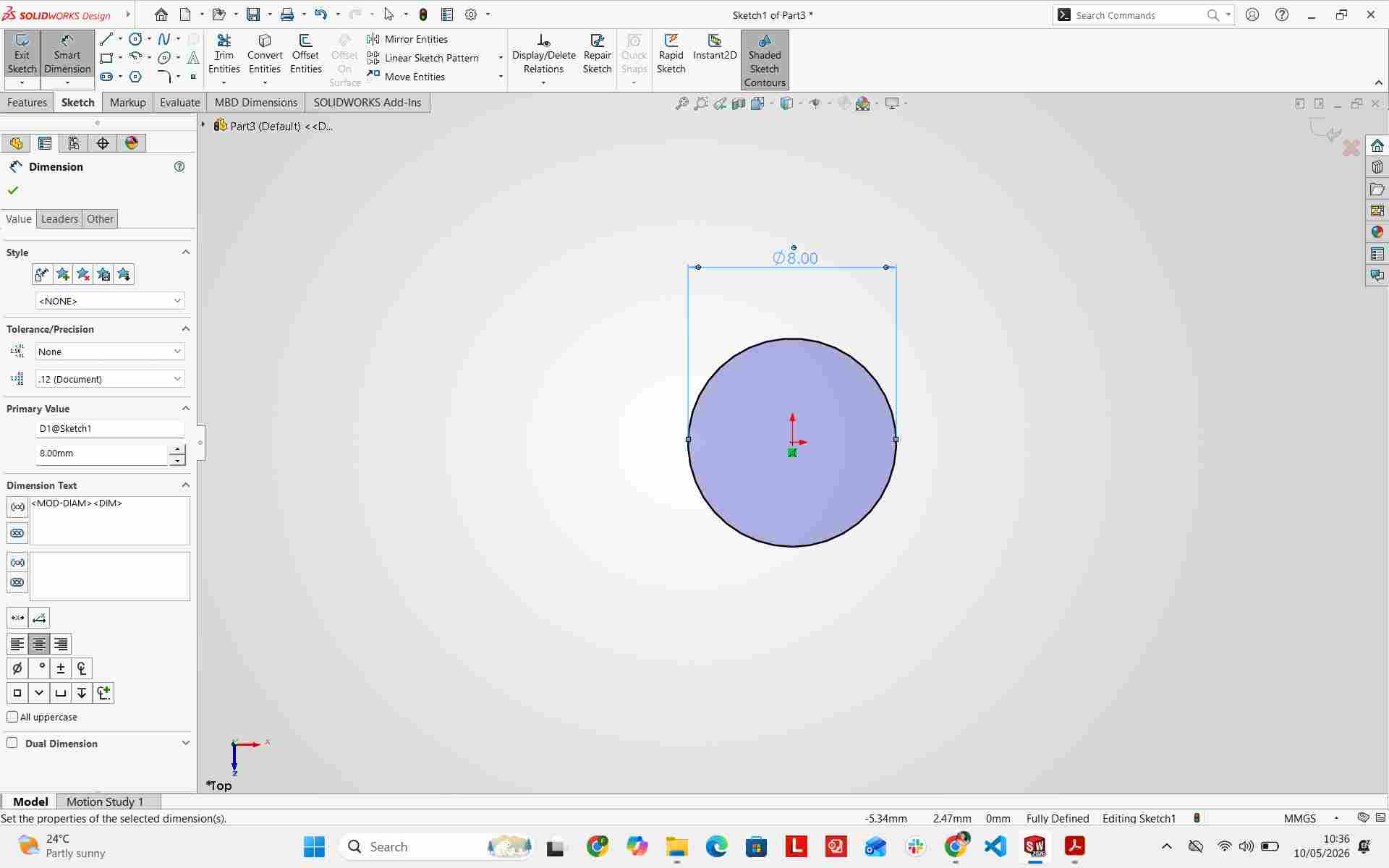
Initial circle sketch on Top Plane
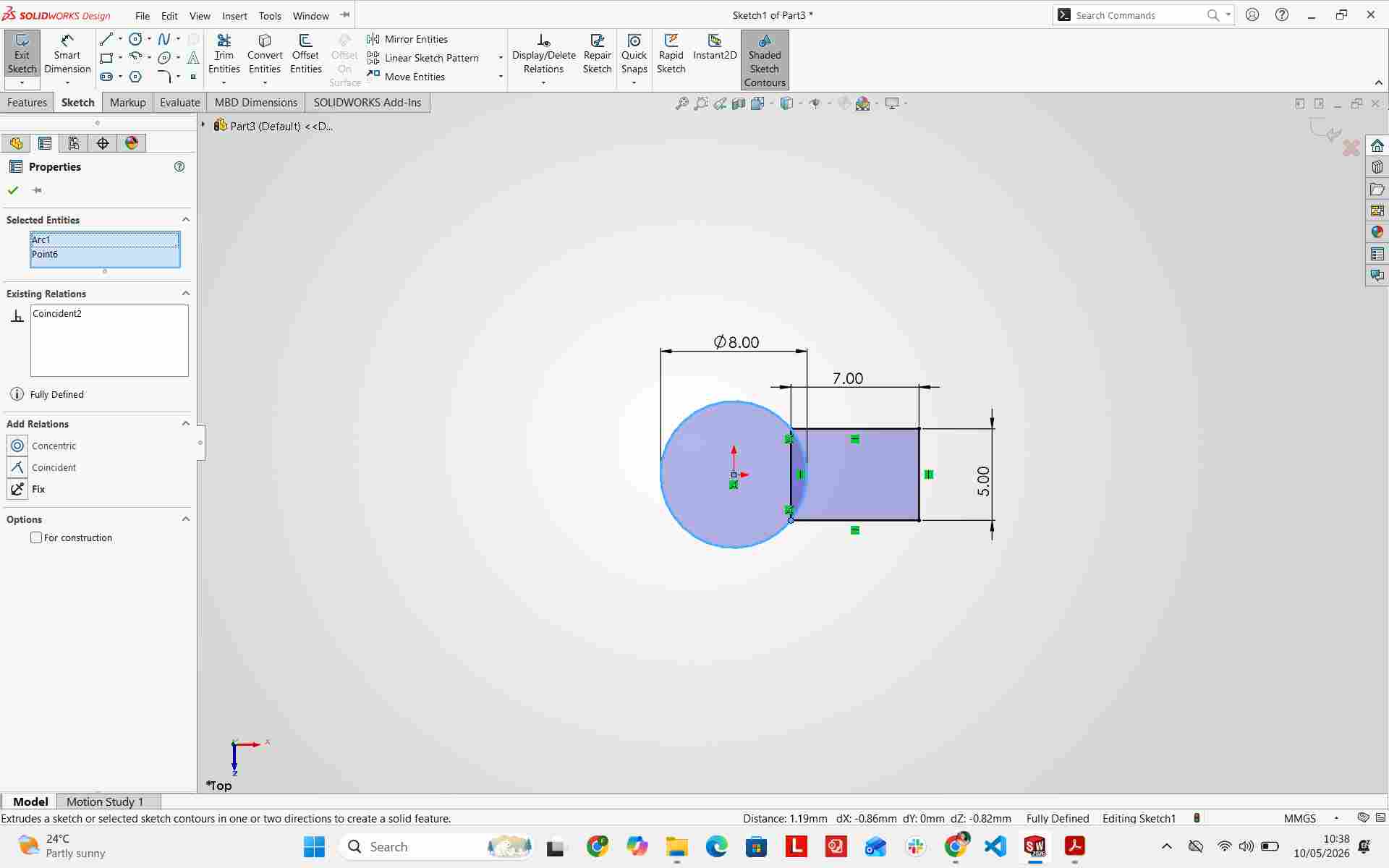
Adding rectangle geometry and geometric constraints
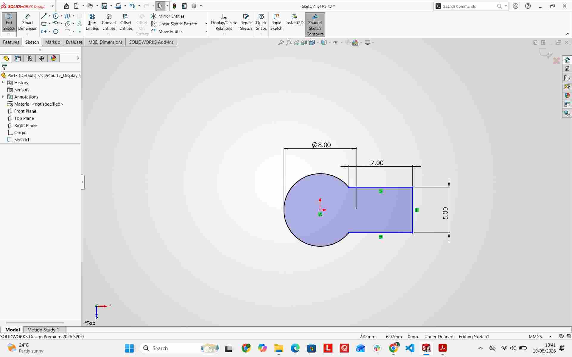
Trimming entity intersections to form a single continuous profile
Base Extrusion
The sketch was converted into a 3D base using the Extrude Boss/Base feature with a height of 1.50mm.
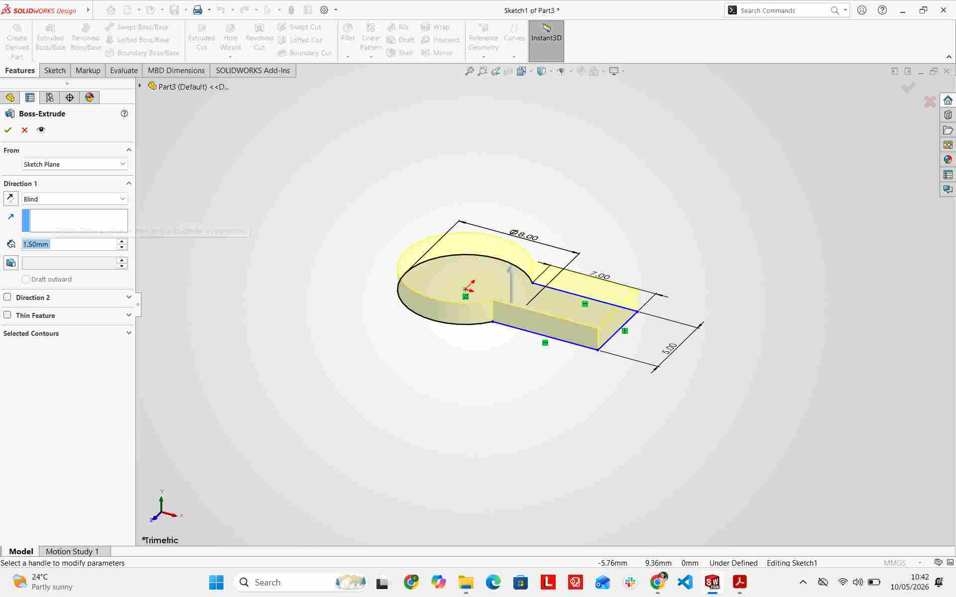
Base extrusion feature setup in SOLIDWORKS
Adding Reference Planes
To create a lofted shape, I needed a second profile at a higher elevation. I added a Reference Plane offset from the Top Plane.
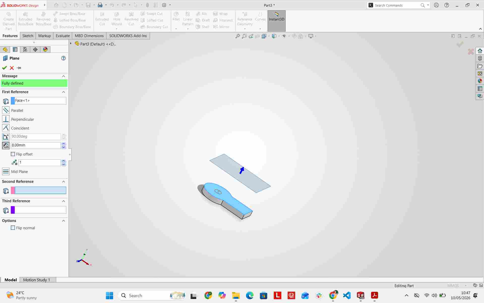
Creating an offset reference plane for lofting
Sketching the Top Profile
On the new plane, I sketched a smaller circle. This serves as the end point for the lofting transition.
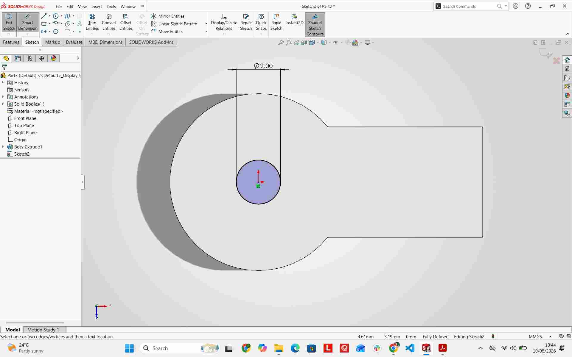
Sketching top circle profile on new reference plane
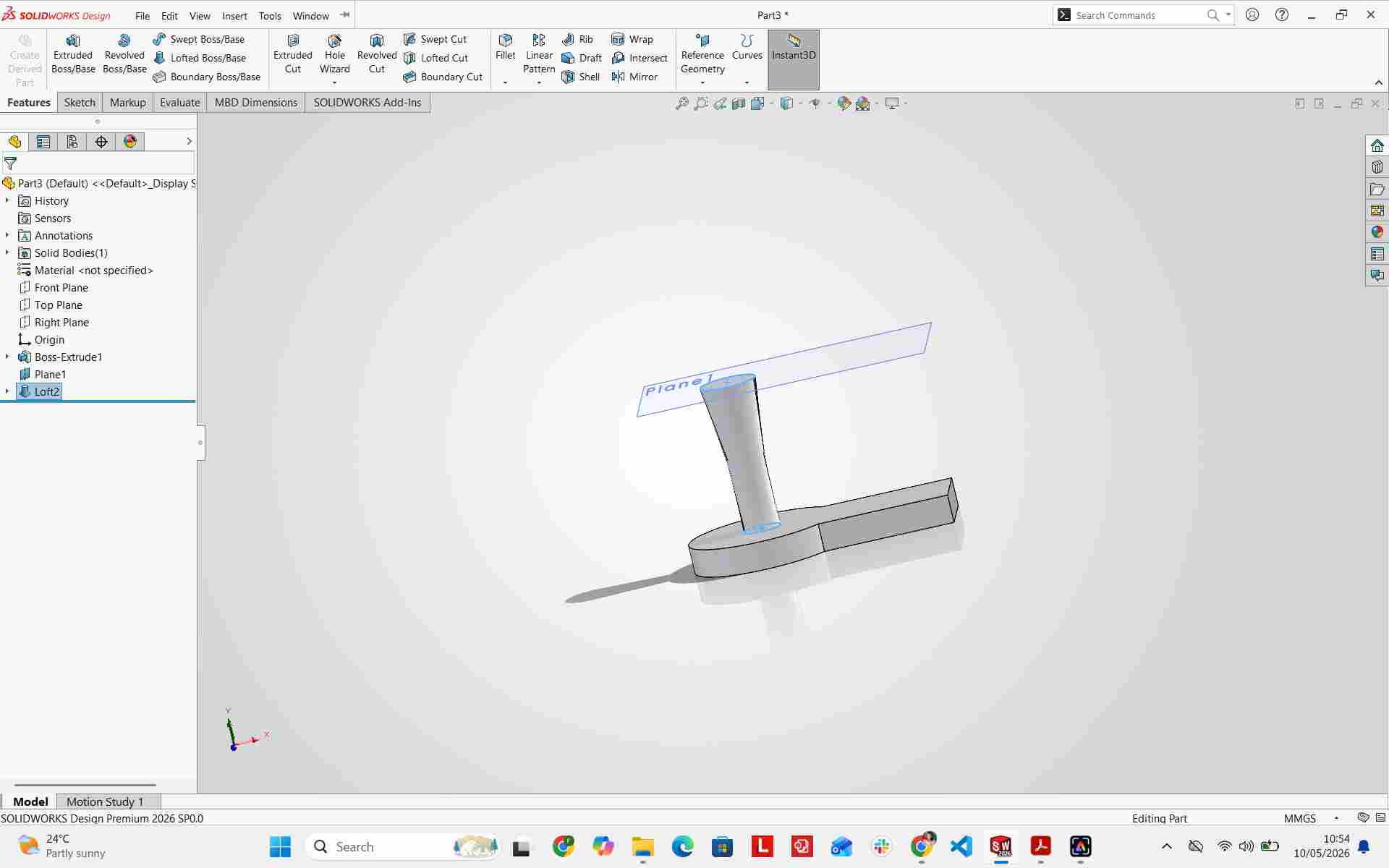
Initial lofting preview between top and bottom profiles
Lofted Boss/Base
I used the Loft tool to connect the base sketch to the top circle. This creates a smooth, tapered organic shape which is ideal for easy demolding.
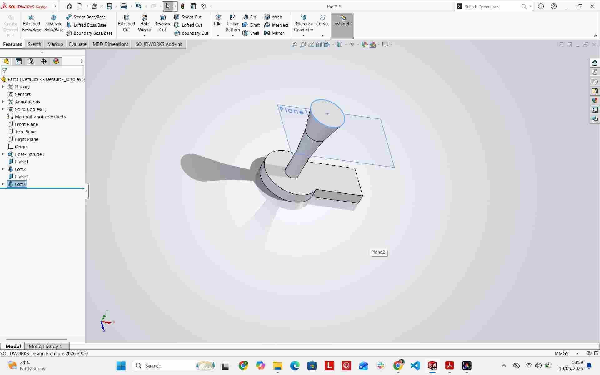
Completed lofted positive feature model
Creating the Mold Cavity
Once the "positive" part was ready, I designed a rectangular block around it. Using boolean operations, I subtracted the part from the block to create the Negative Cavity.
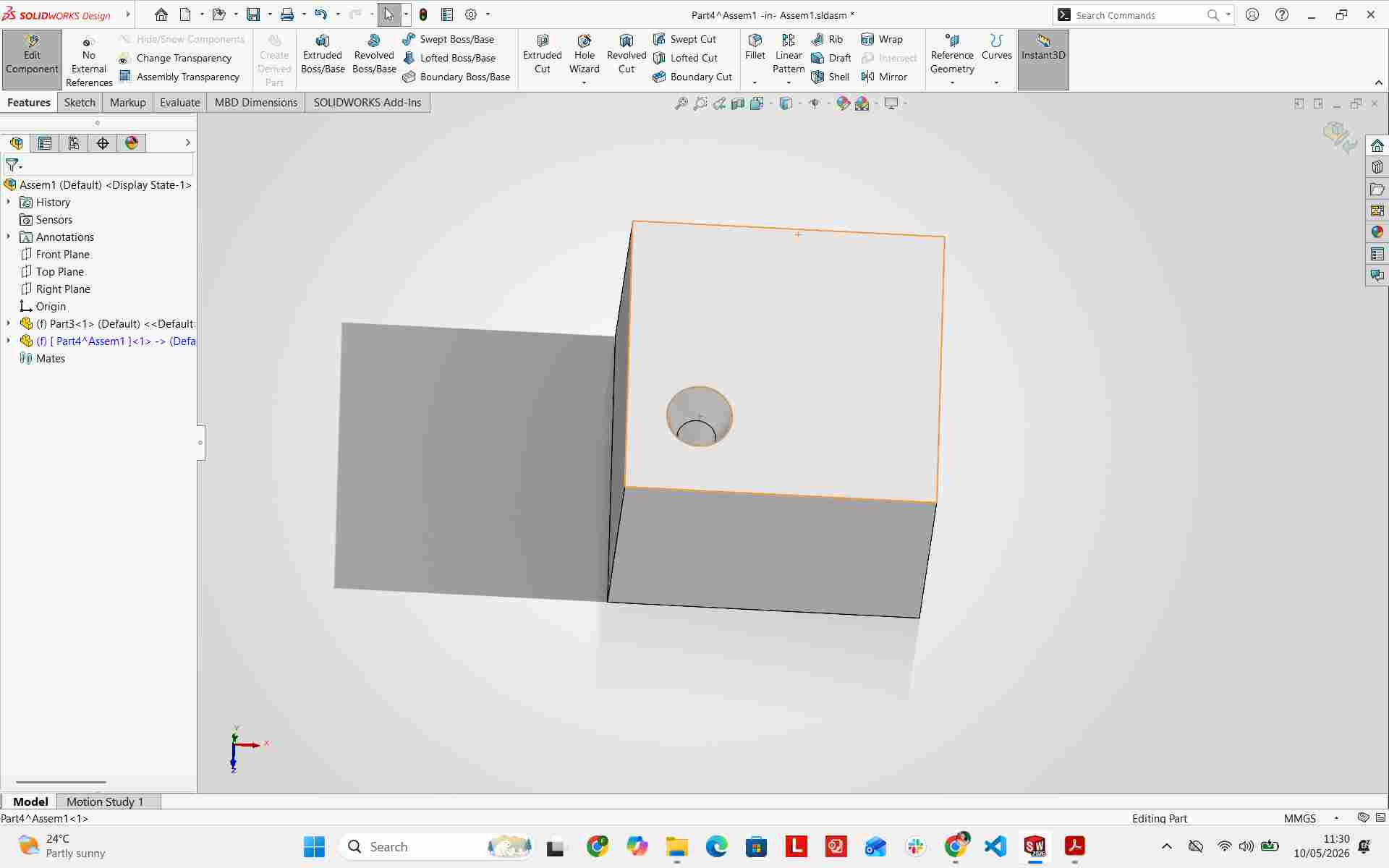
Boolean subtraction creating the internal negative mold cavity
Final 3D Review
The final design shows the mold ready for production with smooth surfaces and proper draft angles.
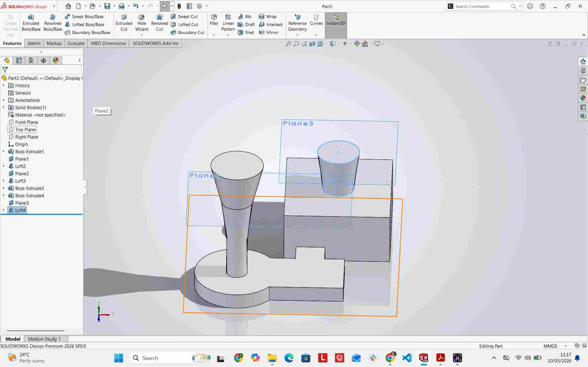
Final 3D mold render with verified draft angles
Machine Preparation & Toolpath Settings
The mold was imported into Creality Slicer 4.8 to prepare the print files and configure explicit parameters to minimize manufacturing artifacts:
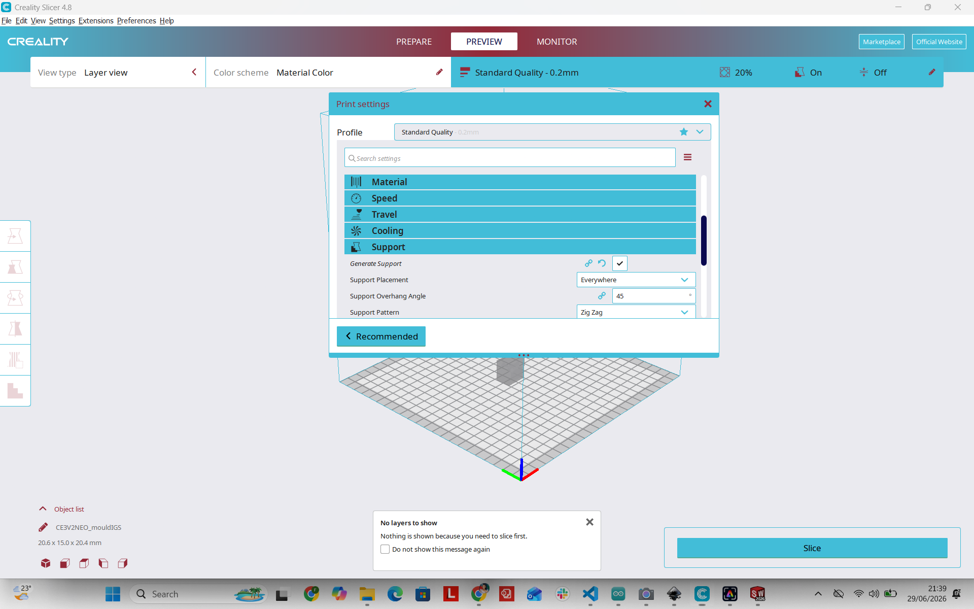
Imported STL geometry ready for slicing parameters setup
- Layer Height: 0.12 mm (Fine resolution to minimize stair-stepping)
- Infill Density: 20% Gyroid (For structural rigidity under casting compression forces)
- Print Speed: 45 mm/s (Slower speed to increase outer wall precision)
- Wall Count: 4 lines (Ensures no structural seepage or chemical leaking through microgaps)
After configuring the print profiles and support structures, the model was successfully sliced with an estimated print time of 33 minutes.
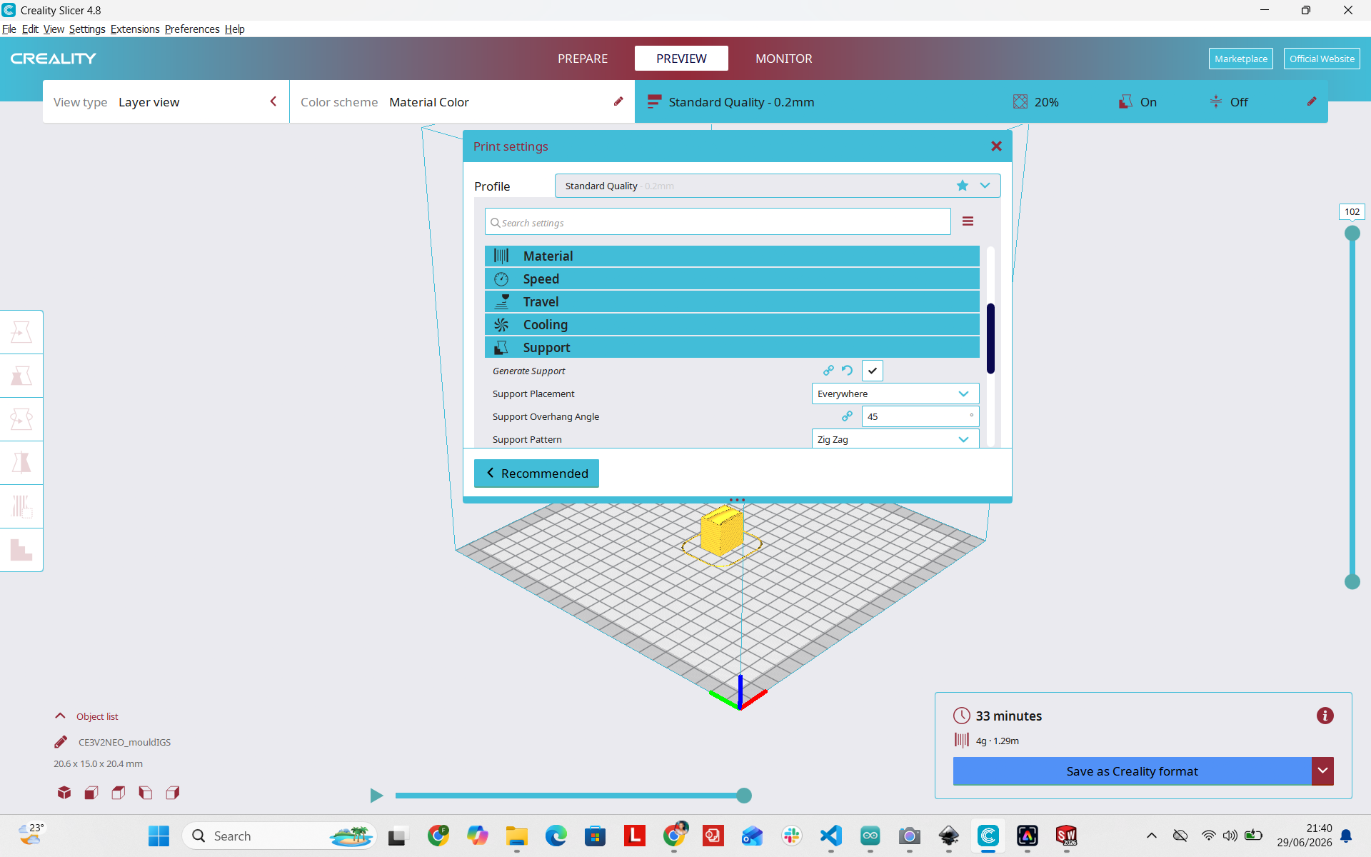
Sliced preview rendering estimated print time and layer paths
Post-Processing for a Smooth Surface Finish
FDM prints inherently present subtle layer ridges which will bind to casting materials or ruin structural aesthetic. To achieve a perfectly smooth finish free of production lines:
- Mechanical Sanding: I progressively sanded the interior cavity using 400-grit, 800-grit, and finally 1200-grit wet sandpaper.
- Surface Sealing: Applied a microscopically thin coating of low-viscosity epoxy glaze coat to fill remaining microscopic ridges and allowed 12 hours to cure.
- Release Agent Application: Applied a thin spray layer of Universal Mold Release to prevent physical material adhesion.
Results
- Completed a precise 3D mold design in SOLIDWORKS.
- Ensured smooth surface finish by choosing appropriate lofting techniques and meticulous post-processing validation.
- Verified all dimensions for casting material volume calculation.
Hero Shots
Fabricated 3D printed negative mold
Final cast resin part with smooth surface finish
Queen Model Design Iteration & Mold Challenges
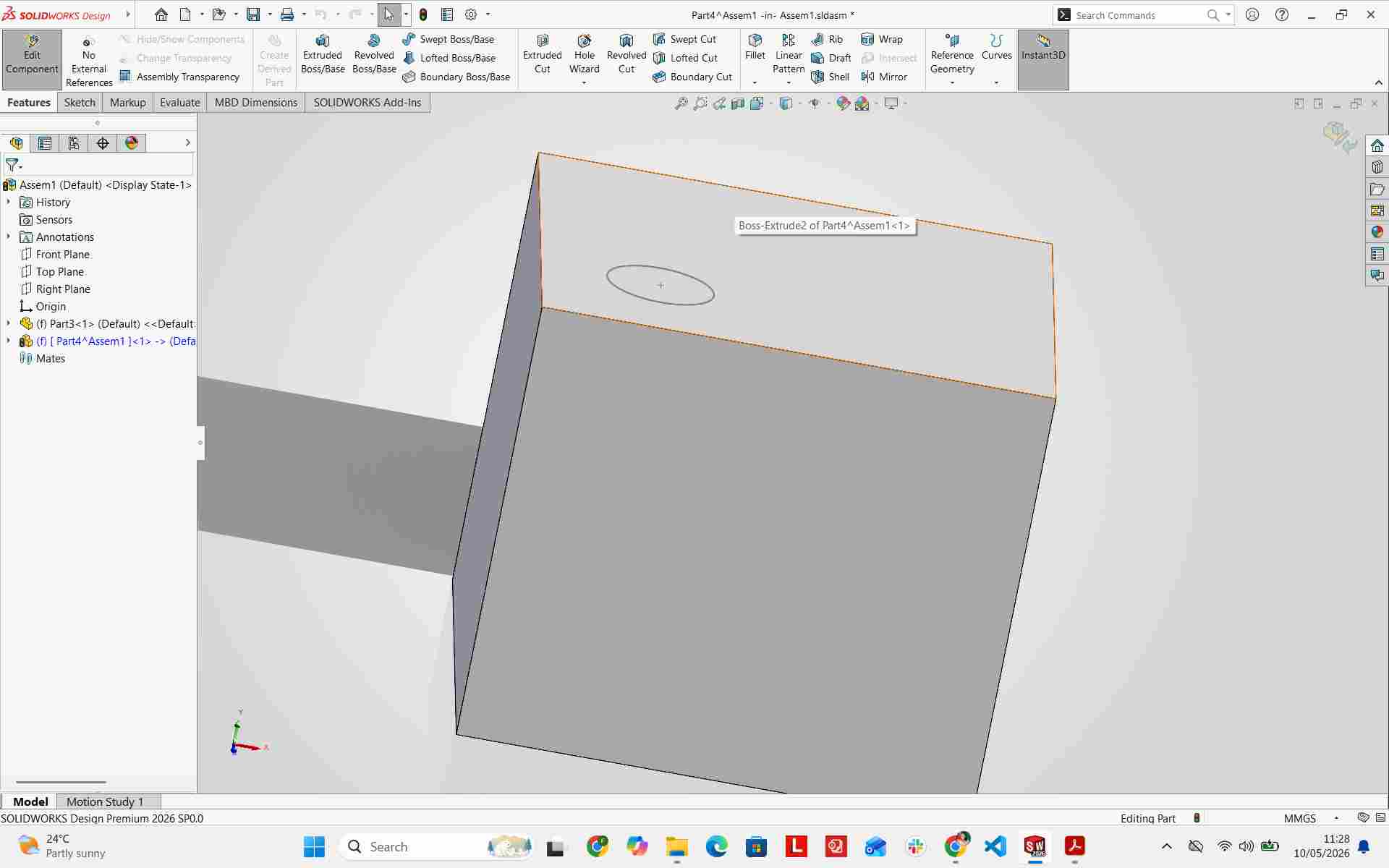
Initial Design Challenge: Off-Axis Geometry & Lockup
My first attempt at creating the Queen model resulted in an impossible geometry for standard two-part molding. The initial concept featured a tapered cylinder rising from the base at a steep angle.
Initial CAD concept showing off-axis geometry and severe undercuts
- Severe Undercut: The off-axis, tilted cylinder created a major undercut. In a standard two-piece split mold, this feature locks the part inside the mold cavity, preventing vertical ejection without destroying the mold or tearing the cast piece.
- Demolding Shear Stress: The narrow junction where the tilted cylinder met the base plate created a high stress point. Demolding forces would easily snap the post off at the joint.
- Air Trapping & Venting: The angled top face of the cylinder formed a natural pocket for air bubbles. Without dedicated side vents along the tilt axis, the top of the cast piece would suffer from severe void defects.
Design Strategy: Symmetrical Queen Profile
To resolve these manufacturing issues while maintaining the visual style of a chess Queen, I designed the piece around a vertical central axis of symmetry. centering the geometry eliminates off-axis undercuts and allows for clean demolding using a classic two-part cavity layout.
Here I designed the half part of the queenand I added the dimensiondimesions to it to have a complete design and functional mold
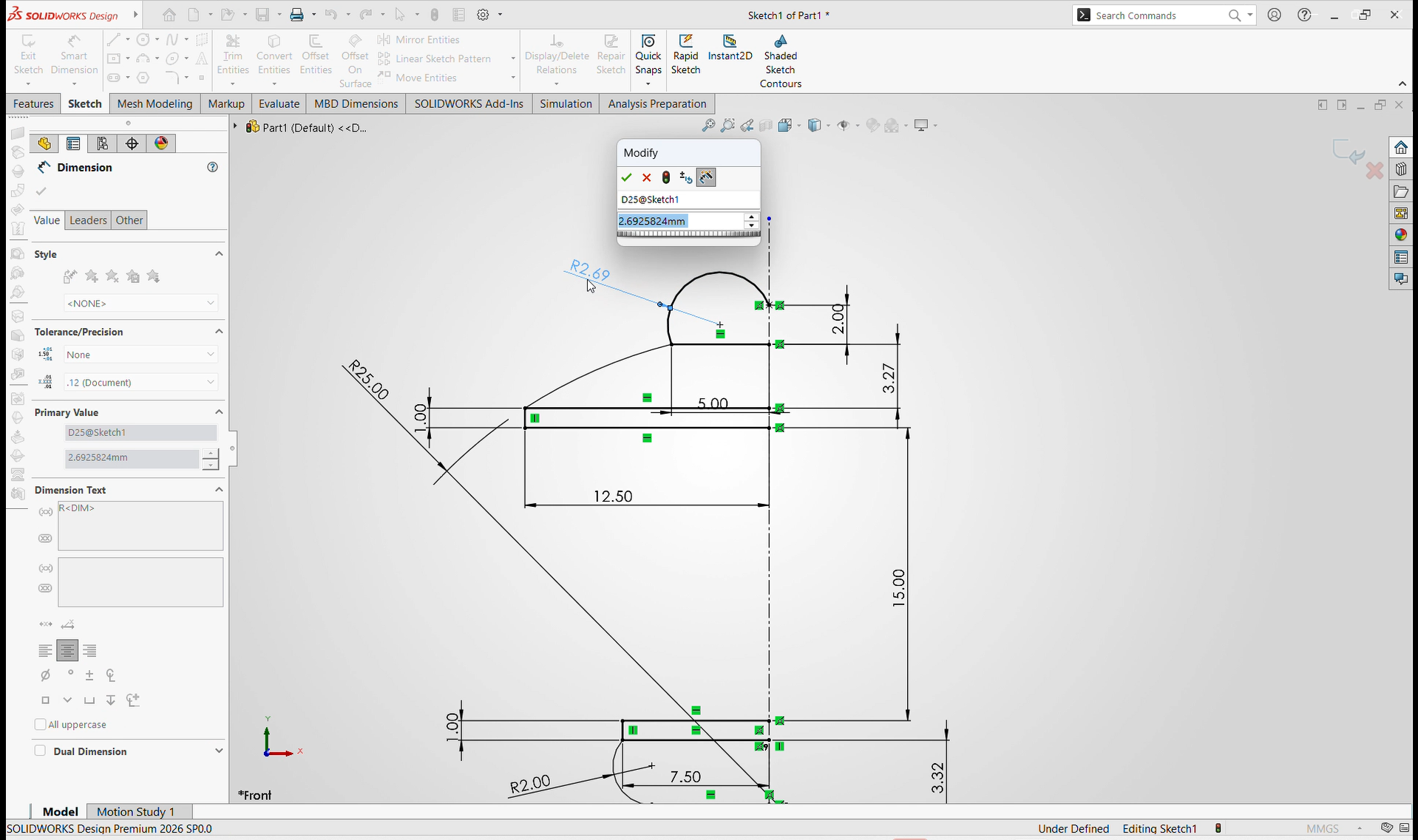
2D Axis & Profile Sketching: Created a revolved profile sketch on the Front Plane. Defined the base footprint, a smooth concave side curve R90 mm radius, and the top crest R12.50 mm radius with an overall body height of 25.00 mm.
Fully dimensioned 2D sketch with central axis of revolution
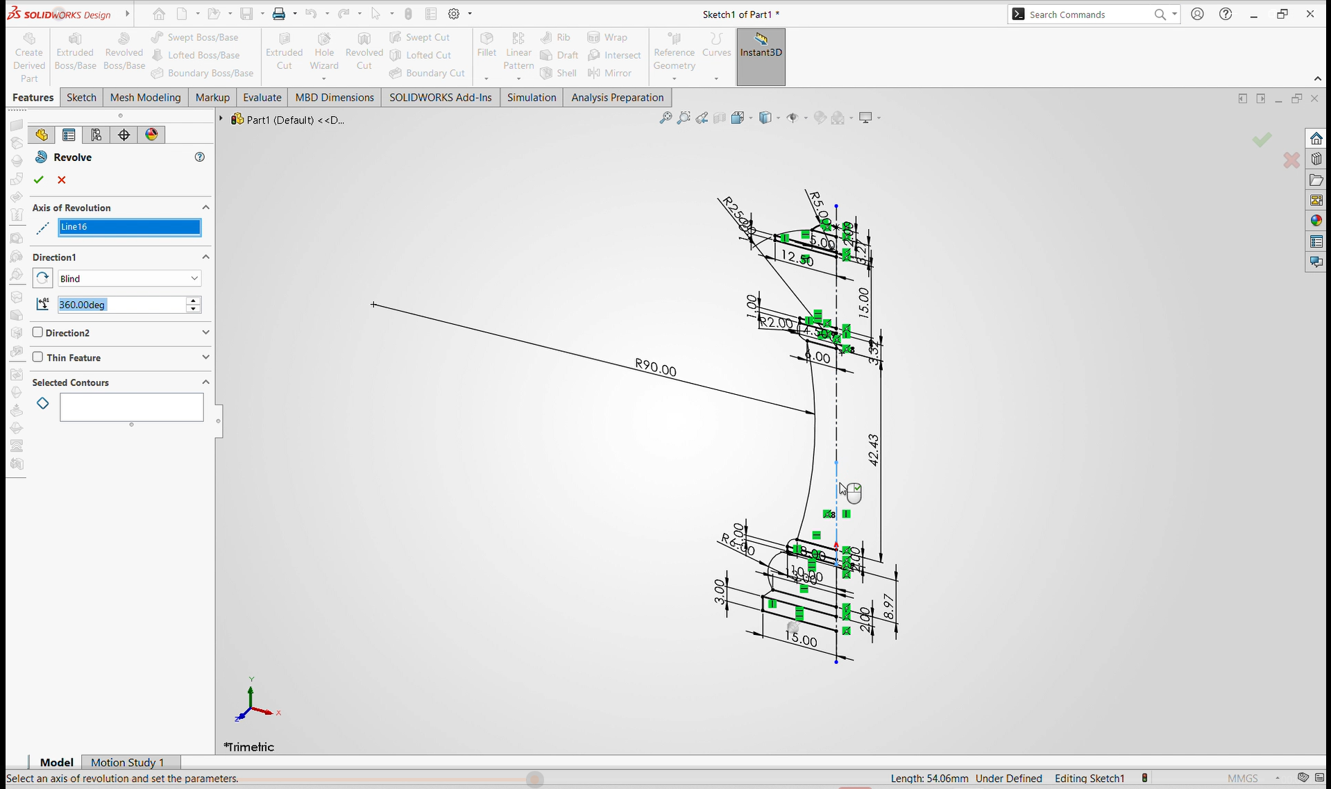
SolidWorks Modeling Workflow
Completed 360 degree Revolved Boss/Base feature
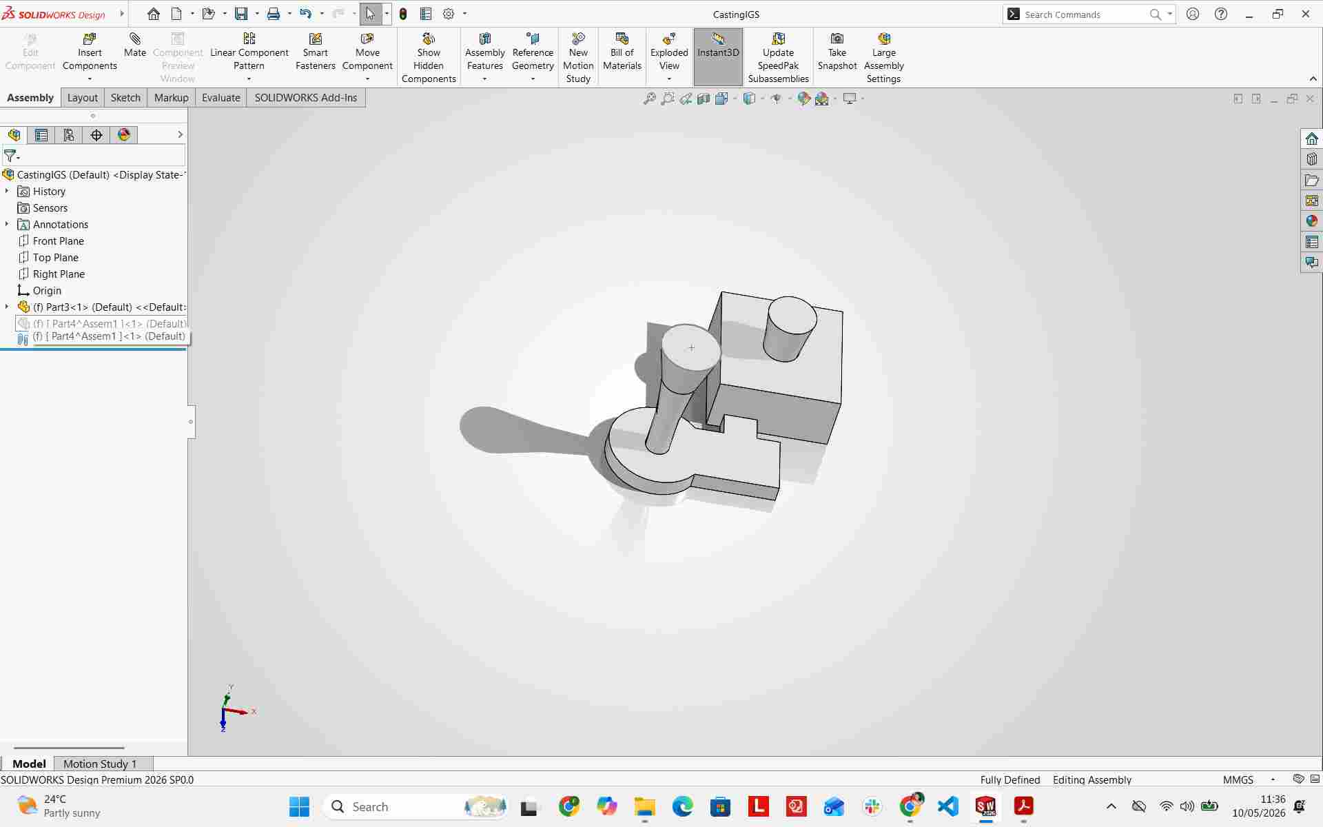
Here is the final design but there is the missing part as you can see it so I have to edit features and add the line in there so that the design can full connected and fully defined.
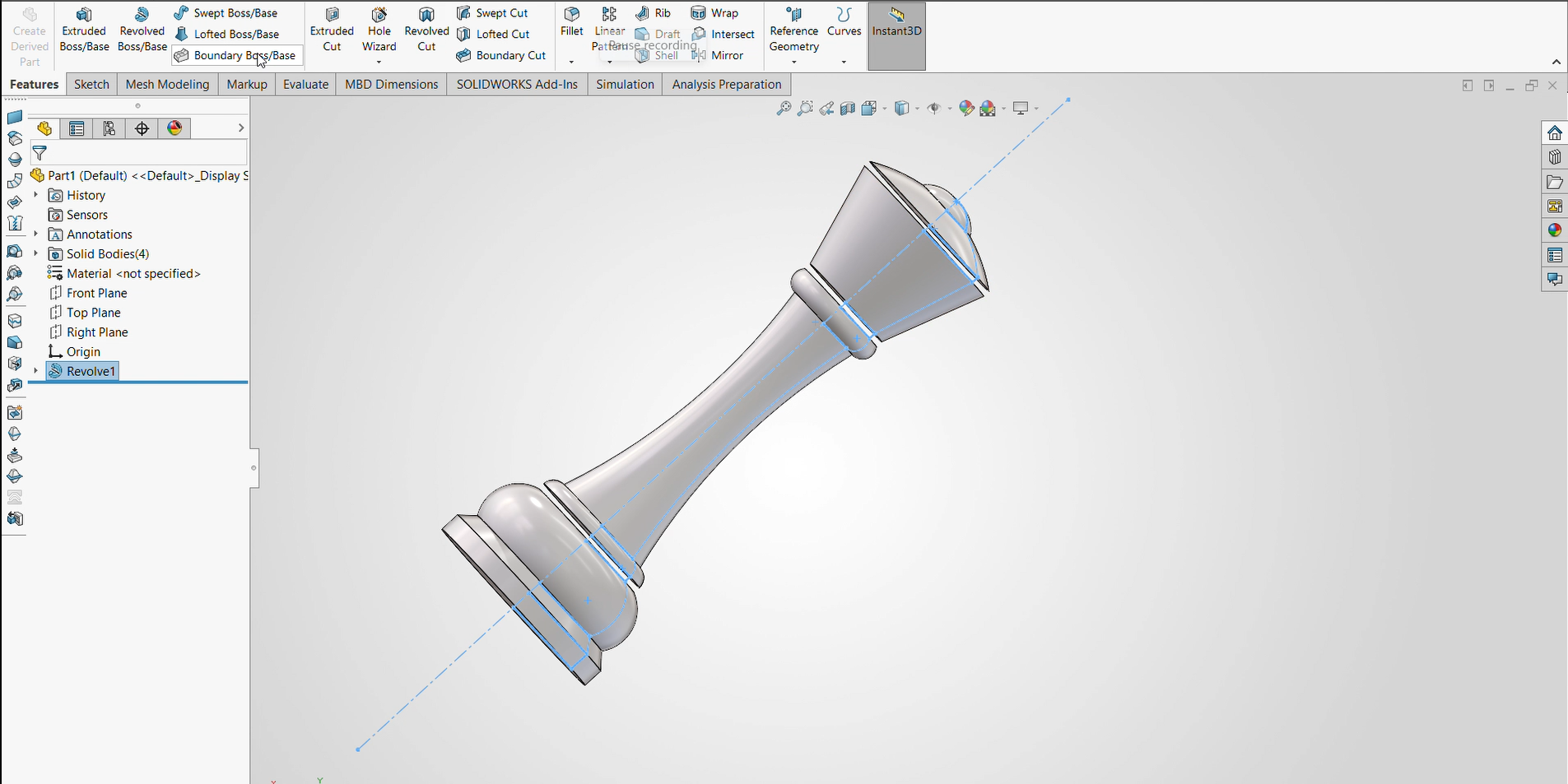
I have edited the features and added the missing line to ensure the design is fully connected and defined.
To have complete design I used the revolve boss to have functional and casting ready design of the queen
Adding the casting design
during the assembly of the queen and the mold to have a complete design and functional mold
Enclosure Block Assembly: Modeled a solid rectangular block surrounding the Queen geometry and established a central parting line plane passing directly through the center axis.Enclosing rectangular block with central parting line plane
Re-centered symmetrical profile sketch on Front Plane
Cavity & Split Operations: Applied Insert > Features > Cavity to subtract the Queen's volume from the solid block. Then used Insert > Features > Split along the reference plane to divide the block into two distinct mold halves (Cope and Drag).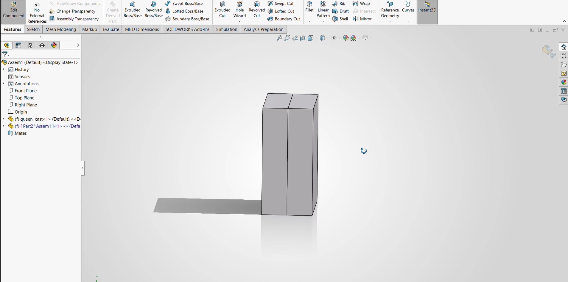
Subtracted cavity and split two-piece mold halves
Draft Angle Verification: Applied a uniform $2^\circ$ draft angle across all vertical transitions to guarantee seamless ejection during demolding.Design Workflow & Demolding Demonstration
Video demonstration of the CAD workflow and mold separation feature split
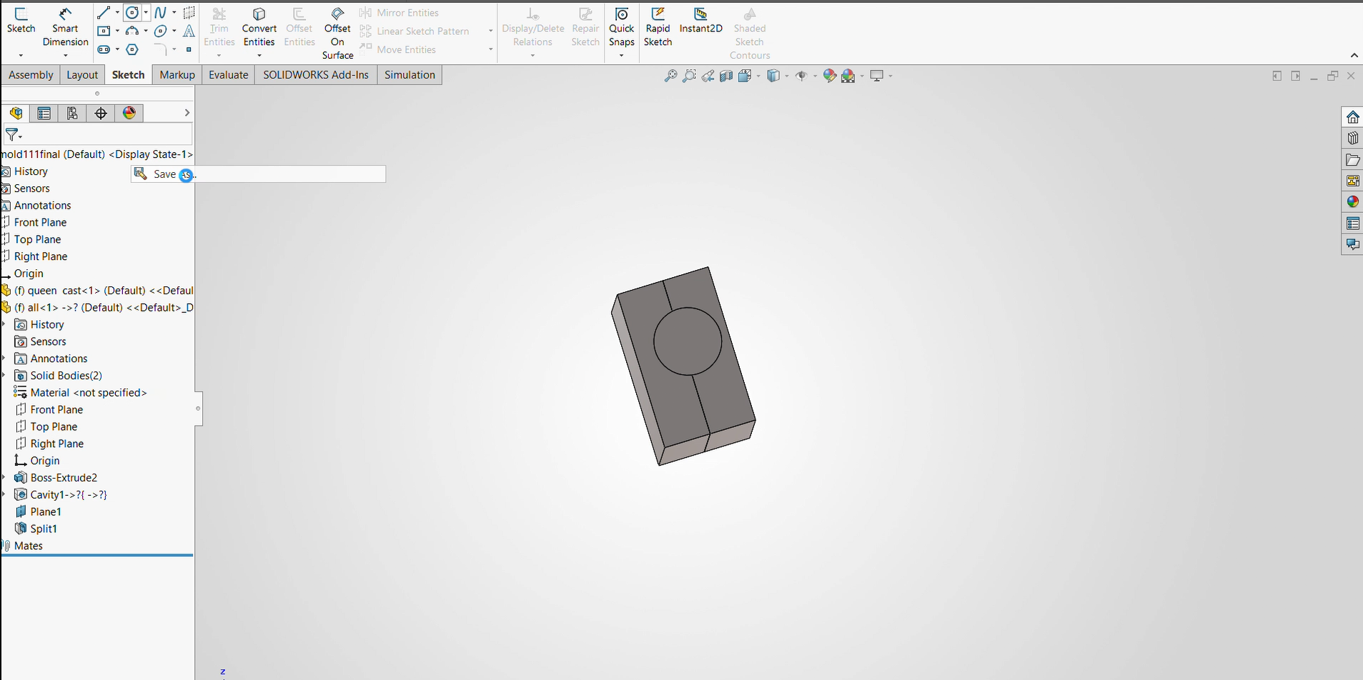
Here is the final design of both mold halves:
Challenges & Solutions
1. Non-manifold Geometry
Cause: Overlapping lines in the initial sketch.
Solution: Used the "Trim Entities" tool to ensure a single closed loop.
2. Surface Ridges
Problem: Rough transitions in the loft.
Solution: Adjusted the "Start/End Constraints" in the Loft property manager to "Normal to Profile".
3. Micro-Adhesion Demolding Issues
Problem: Cast pieces initially snagged on un-sanded perimeter layers.
Solution: Integrated a uniform draft angle of 3 degrees into the design files and performed the micro-sanding regimen outlined in post-processing.
What I Learned
- Difference between positive and negative mold design structures.
- Importance of Draft Angles for clean demolding without ruining parts.
- Using Reference Geometry (Planes) for complex 3D shapes.
- Safety precautions when handling casting chemicals (MSDS metrics, mandatory PPE usage, local ventilation parameters).
Downloads & Design Files