// Week 12
Networking and Communications
Introduction
This week focused on establishing communication between multiple microcontroller systems. The goal was to create a functional network where one board transmits data and another receives and processes it for display.
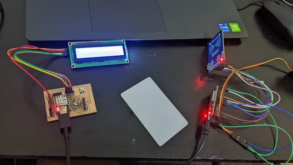
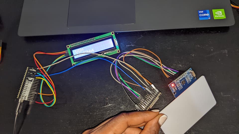
In my implementation, I built a two-node wired communication system using two ESP32 microcontrollers. One node functions as a sender (input node) interfaced with an RFID reader, while the second node acts as a receiver (output node) equipped with an I2C LCD display.
The core communication protocol used was UART (Universal Asynchronous Receiver-Transmitter / Serial Communication), where data packets are transferred between boards using cross-connected TX/RX lines and a common ground reference.
Objectives
Group Assignment
- Send a message between two projects or microcontroller boards.
- Understand communication protocols, timing requirements, and signal transmission integrity.
→ View Group Assignment Documentation
Individual Assignment
- Design and connect multiple nodes with unique network addressing schemes.
- Implement communication pipelines between dedicated input and output devices.
- Document the complete development workflow, hardware challenges, and final operational results.
Tools & Technologies
Hardware Components
- ESP32 Microcontrollers (x2): Dual-core nodes executing sender and receiver tasks.
- MFRC522 RFID Reader: 13.56 MHz RFID module used to read unique IDs from cards/tags.
- RFID Card/Tag: High-frequency transponder storing fixed identification payload data.
- 16x2 I2C LCD Display: Visual display module for rendering incoming packet data.
- Jumper Wires: Interconnect cables for crossed TX/RX UART transmission and power lines.
Software & Drivers
- Arduino IDE: Development interface for writing C++ code and monitoring serial buses.
- CP210x USB-to-UART Bridge VCP Driver: Essential host driver for ESP32 board detection.
Software Libraries
SPI.h– Hardware SPI library for interfacing with the MFRC522 reader.MFRC522.h– Driver library for MFRC522 RFID card detection and UID parsing.Wire.h– Two-Wire I2C bus interface library.LiquidCrystal_I2C.h– Serial I2C character LCD controller library.
Workflow & Implementation
Step 1: Debugging ESP32 Connection & Driver Setup
Initially, I encountered a critical issue where the ESP32 board was not detected by my operating system, preventing uploading from the Arduino IDE.
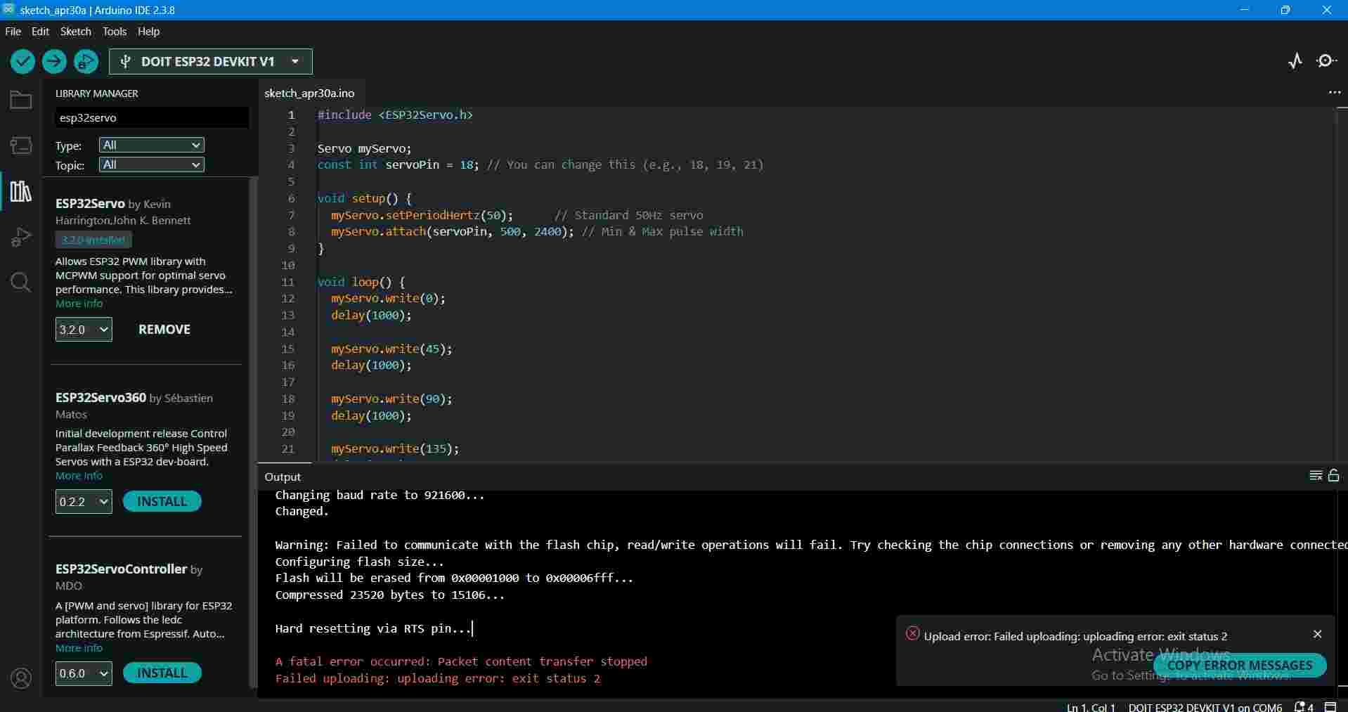
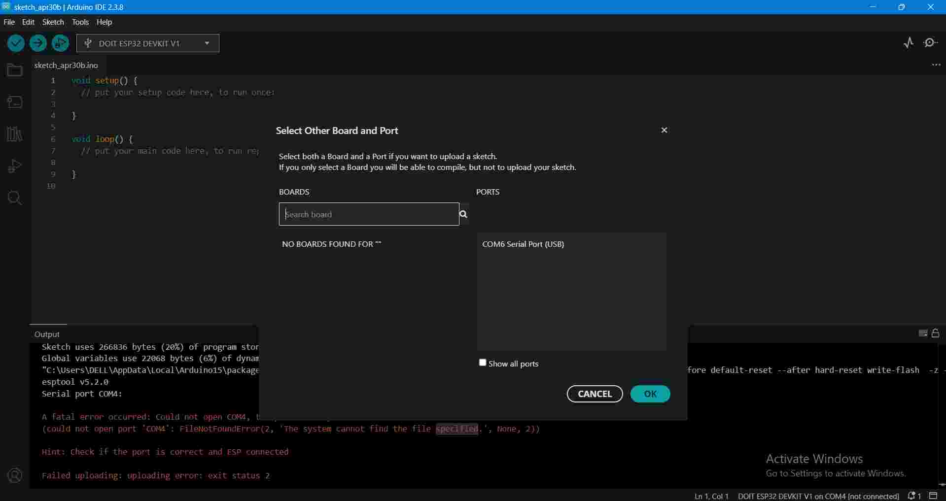
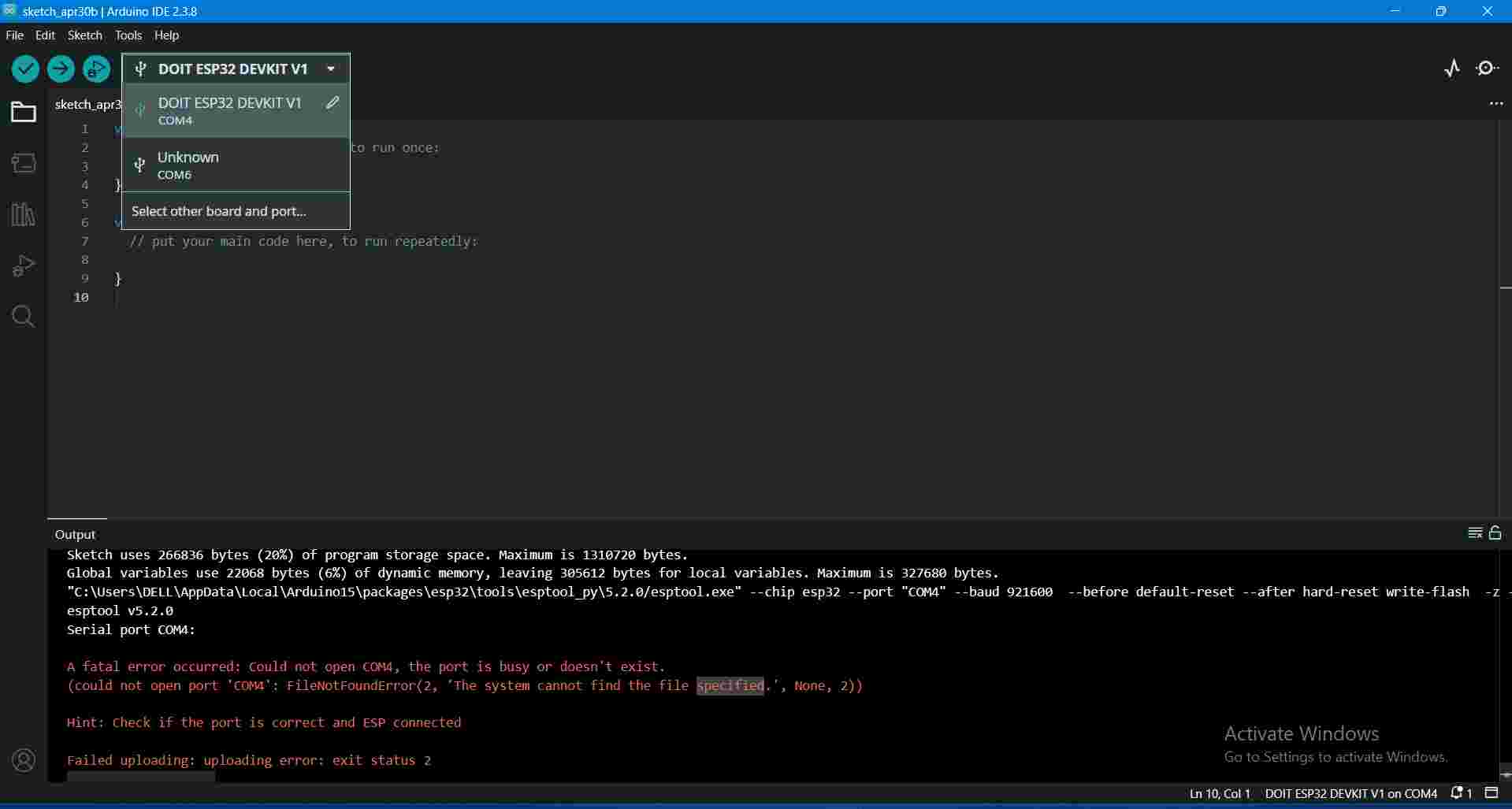
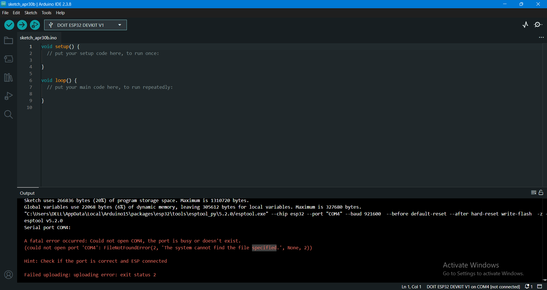
Upon inspecting Windows Device Manager, I noticed a driver warning indicator showing that the computer lacked the required CP210x USB-to-UART Bridge Driver.
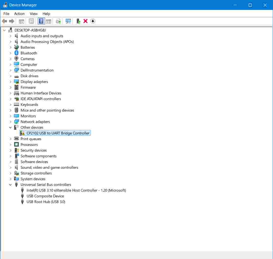
Troubleshooting Steps & Resolution:
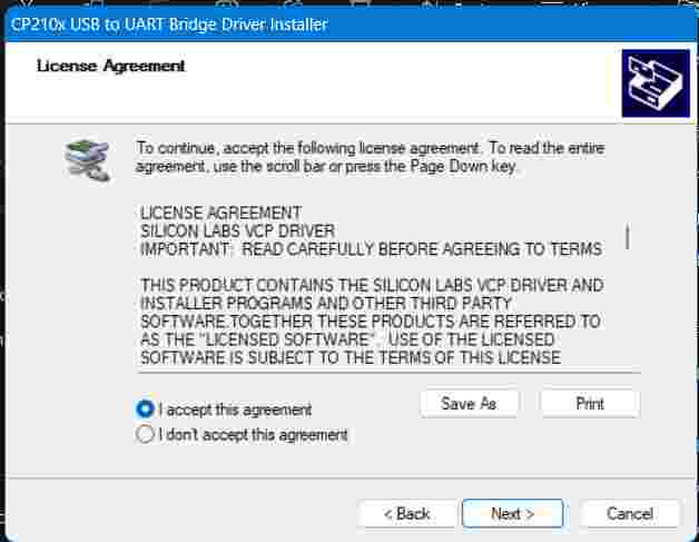
- Downloaded the Silicon Labs CP210x VCP drivers from the Silicon Labs Driver Download Page.
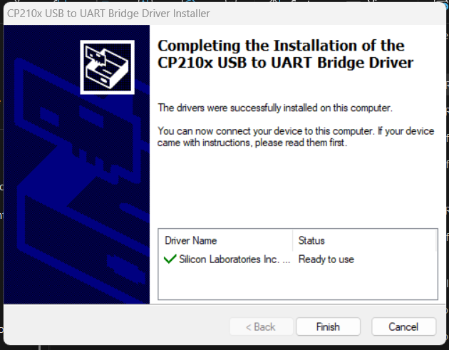
- Extracted and executed the driver setup installer on the host workstation.
- Rebooted the workstation and reconnected the ESP32 via USB.
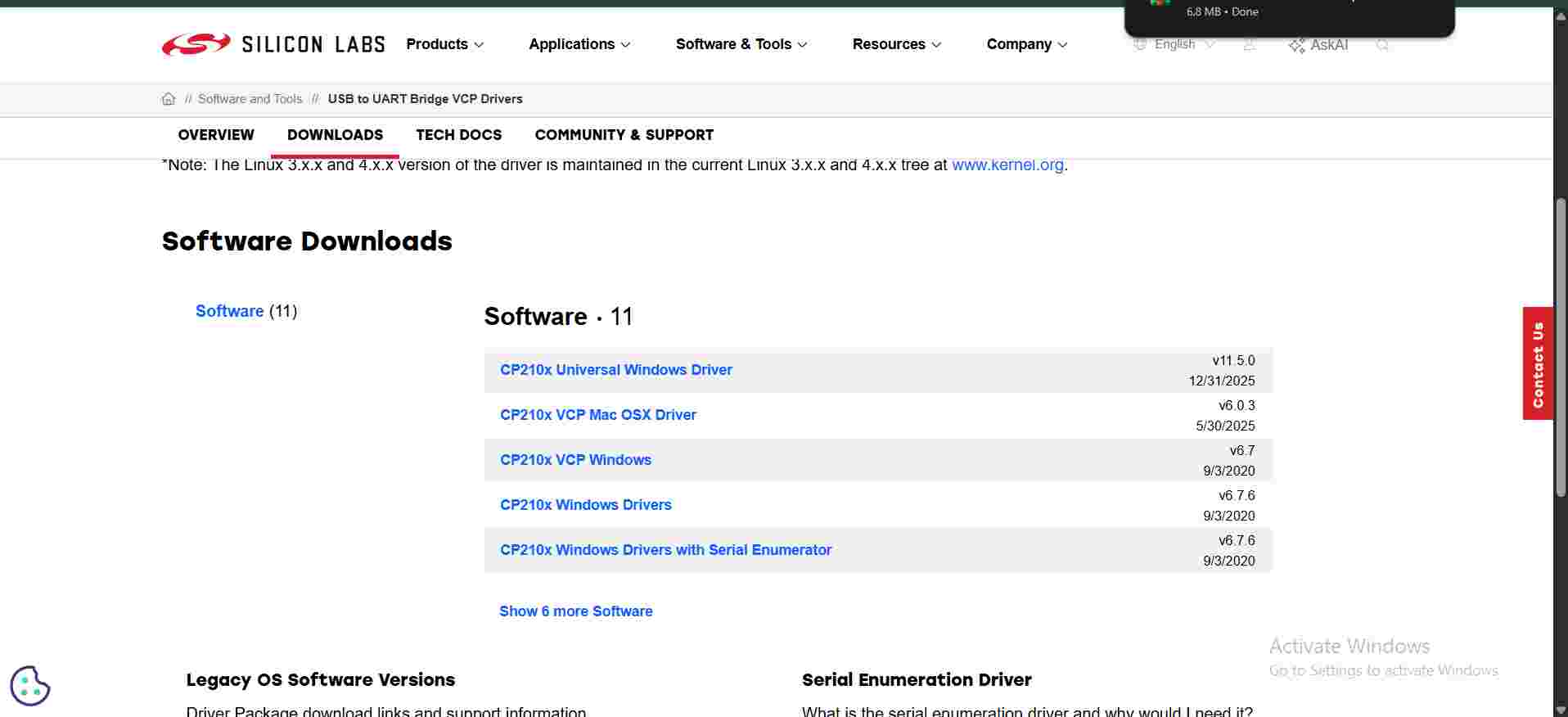
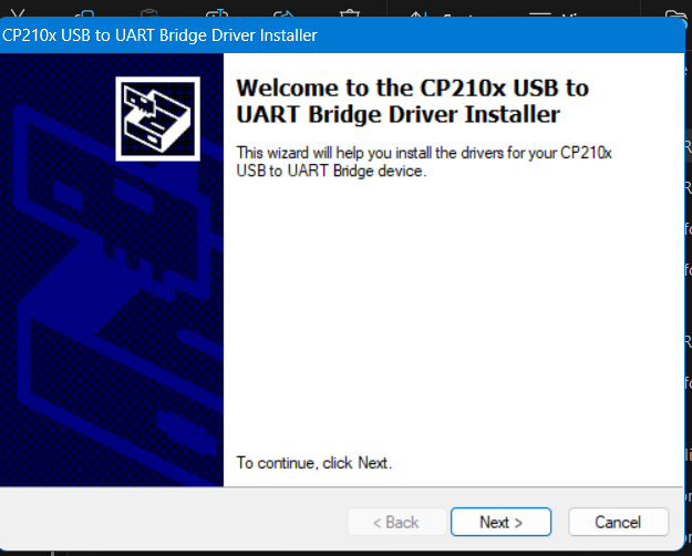
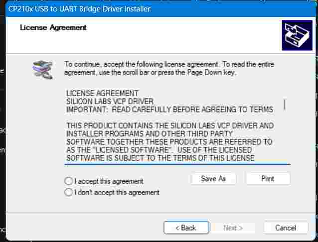
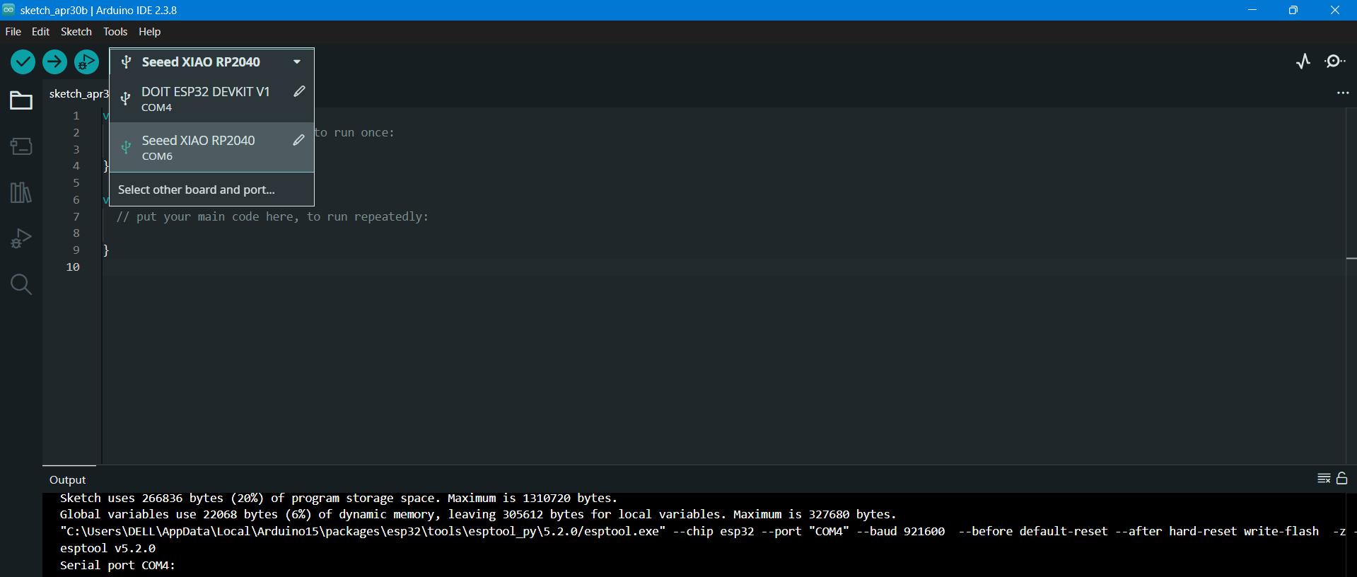
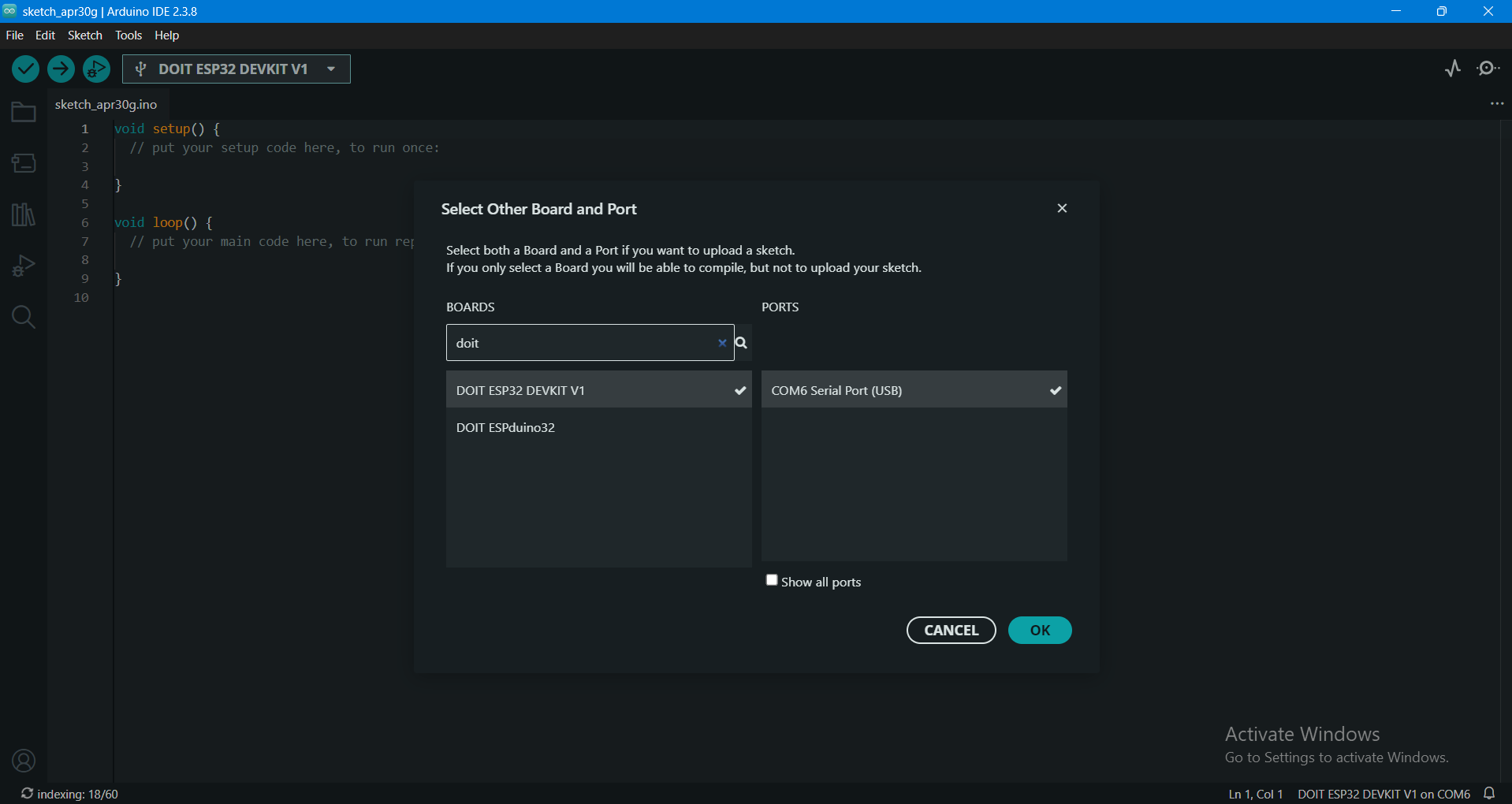
After installation, the Virtual COM Port (COM) appeared correctly in Arduino IDE:
Step 2: System Architecture (Two-Node Network)
I structured a master-slave styled serial communications system consisting of two independent processing nodes:
- Node 1 (Sender): ESP32 reading card UIDs via SPI from an MFRC522 RFID reader.
- Node 2 (Receiver): ESP32 listening on its RX line and printing payloads to an I2C LCD screen.
Step 3: ESP32 Pinout Mapping & Independent Node Verification
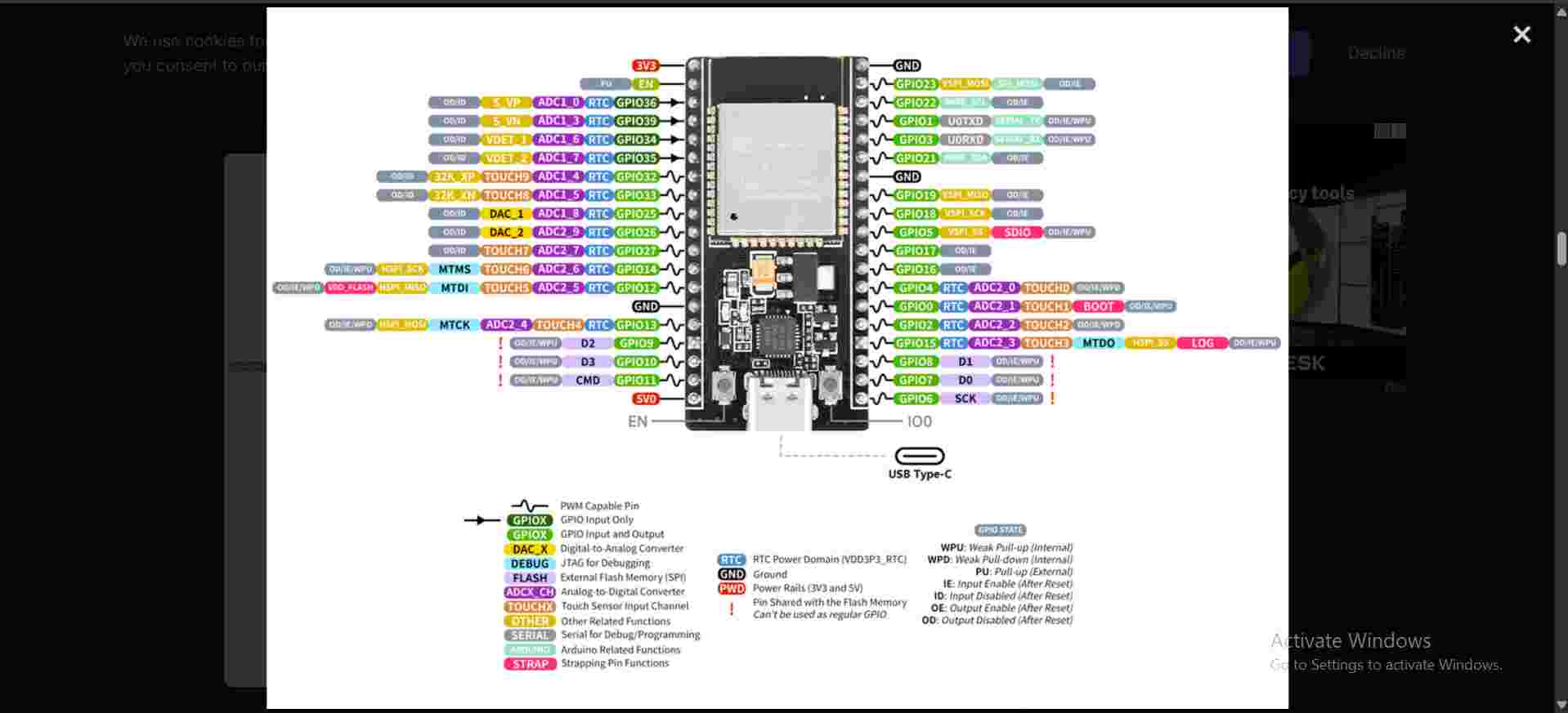
I consulted the standard ESP32 pinout reference to identify dedicated SPI, I2C, and UART pins prior to hardware assembly.
Testing Node 1: RFID MFRC522 Reader
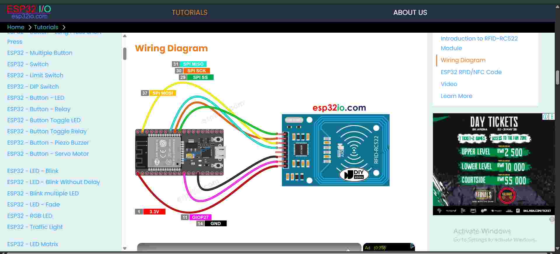
The MFRC522 module uses the high-speed SPI (Serial Peripheral Interface) protocol. I connected SCK, MISO, MOSI, SDA, and RST to default ESP32 SPI pins and uploaded a test sketch to confirm UID parsing.
RFID Standalone Demonstration Video
Testing Node 2: 16x2 I2C LCD Display
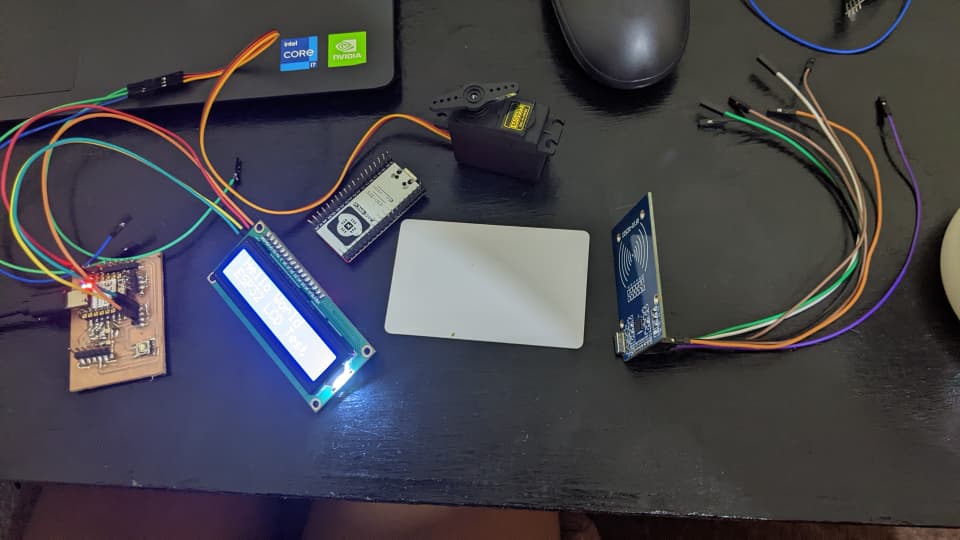
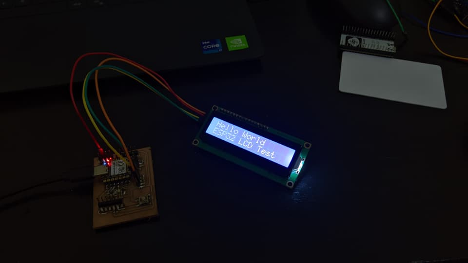
I independently verified Node 2 using an I2C scanner and a simple LCD initialization sketch to confirm contrast and character display.
Step 4: Establishing Hardware UART Interconnection
UART transmission requires crossing data signals between nodes while bonding ground potential:
- Sender TX (Transmit Pin) → Receiver RX (Receive Pin)
- Sender GND → Receiver GND (Common Ground Reference)
Note: Crossing TX to RX is fundamental so that outgoing bit toggles align directly with the remote node's input shift register.
Step 5: Node 1 Payload Transmission Code
When an RFID card is swiped, Node 1 parses the hexadecimal byte array into a string payload and streams it down the serial line:
// Transmit parsed UID string over UART Serial
Serial.println(uid);
Step 6: Node 2 Reception & LCD Rendering Code
Node 2 checks its hardware serial buffer for incoming newline-terminated byte streams and outputs them onto the LCD screen:
if (Serial.available()) {
  String msg = Serial.readStringUntil('\n');

  lcd.clear();
  lcd.setCursor(0, 0);
  lcd.print("Received:");

  lcd.setCursor(0, 1);
  lcd.print(msg);
}
Step 7: Network Addressing & Message Formatting
To simulate multi-node networking over shared lines, I added sender identification headers (node addressing) to the transmitted payload:
// Formatting payload with Node Source ID
Serial.println("NODE1:" + uid);
This prefix allows receiver nodes to filter and distinguish payload origins in multi-device bus networks.
Results & Validation
- Established stable inter-board UART communication between two separate ESP32 systems.
- Real-time SPI read of RFID UIDs transmitted cleanly over serial line to receiving node.
- Instantaneous rendering of received packet payload on I2C LCD screen.
Data Pipeline Flow:
[Scan RFID Tag] ──SPI──> [Node 1: ESP32] ──UART TX/RX──> [Node 2: ESP32] ──I2C──> [16x2 LCD Display]Complete Network System Demonstration Video
Challenges & Solutions
1. ESP32 Host Connection Failure
Cause: Absence of CP210x USB-to-UART bridge controller drivers on host PC.
Solution: Installed official Silicon Labs VCP drivers and verified active COM assignment in Device Manager.
2. Data Transmission Not Registering on Receiver
Cause: Direct parallel wiring (TX to TX) instead of cross wiring.
Solution: Swapped wire placement so Node 1 TX connected directly to Node 2 RX with common GND.
3. Garbage Characters or Garbled Serial Text
Cause: Baud rate mismatch between sender and receiver serial initialization.
Solution: Standardized both firmware sketches to run at matching 115200 baud rates.
4. LCD Library Compilation Errors
Cause: Conflicting header functions across generic LiquidCrystal repositories.
Solution: Used the standard LiquidCrystal_I2C library compatible with PCF8574 backpacks.
What I Learned
- Fundmentals of UART Serial Communication (TX/RX timing, baud rate sync, common ground requirements).
- Simultaneous management of multiple protocol buses (SPI for RFID, UART for inter-board networking, I2C for display).
- Importance of host VCP drivers in physical hardware debugging environments.
- Implementing sender node address headers to form structured network payloads.
- Systematic unit-testing procedures: validating sensor/actuator nodes individually prior to network integration.