// Week 10
Output Devices
Introduction
This week focused on understanding how microcontrollers interact with the physical world through output devices. Unlike input devices which read environmental data, output devices convert electrical signals into physical actions such as mechanical motion, visual light displays, or sound.
In my work, I explored three distinct output modalities:
- Servo Motor (Actuator): Produces precise, angular mechanical motion.
- I2C LCD (Visual Output): Displays system status and telemetry data in real-time.
- Buzzer & LED (Audio + Visual Feedback): Delivers interactive alerts based on sensor conditions.
The goal was to examine signal timing, power requirements, and control logic interaction within an embedded hardware architecture.
Objectives
Group Assignment
- Measure the power consumption of an output device under load.
- Analyze voltage requirements, peak current draw, and power supply stability.
→ View Group Assignment Documentation
Individual Assignment
- Add an output device to a microcontroller board that you designed and program it to do something.
- Interface actuators, displays, and indicators using logic control loops.
- Analyze device behavior and troubleshoot electrical and software issues.
Tools & Technologies
Hardware Components
- Seeed Studio XIAO RP2040: Primary microcontroller running project control code.
- SG90 Micro Servo Motor: Pulse Width Modulation (PWM) position-controlled actuator.
- 16x2 I2C LCD Module: Serial character display for real-time monitoring.
- LDR Sensor (Light Dependent Resistor): Analog input used to trigger output thresholds.
- Piezo Buzzer: Audio frequency feedback generator.
- Indicator LED: Discrete visual status output.
Electrical Fundamentals
Each output device exhibits distinct electrical characteristics. Understanding continuous vs. peak current, supply voltage levels, and high-frequency control signals is critical to prevent resetting microcontrollers or damaging GPIO pins.
Process & Workflow
PROJECT 1: SERVO MOTOR + LCD DISPLAY
Understanding Servo Motor PWM Signals
A hobby servo motor does not spin continuously like standard DC motors. Instead, internal feedback circuitry positions the output shaft to a specific angle based on incoming Pulse Width Modulation (PWM) control signals at a 50Hz frequency:
- 0° Position: ~1.0 ms high pulse width
- 90° Position: ~1.5 ms high pulse width
- 180° Position: ~2.0 ms high pulse width
The microcontroller communicates position by generating precise pulse timings rather than shifting steady DC voltage levels.
Step 1: Installing the I2C LCD Library
To drive the display using serial I2C protocols (requiring only two data wires), I installed the LiquidCrystal_I2C library in Arduino IDE:
- Open Arduino IDE.
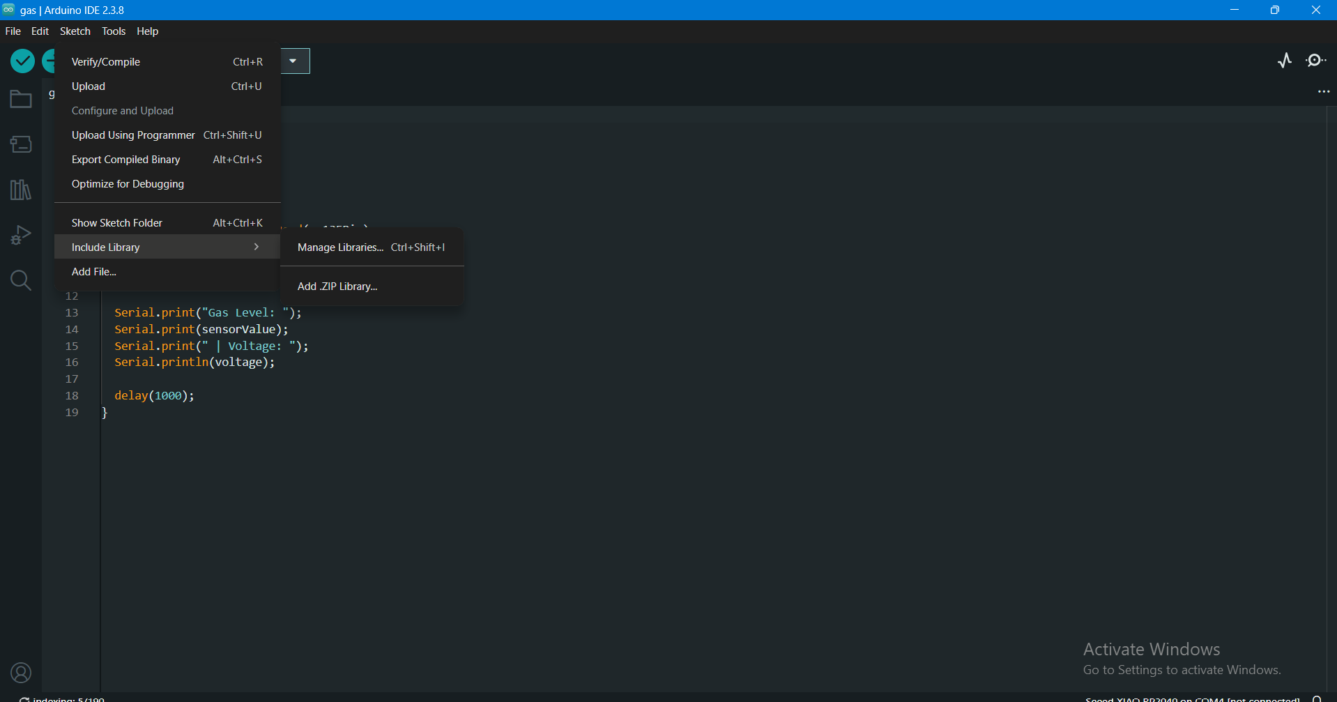
- Navigate to Sketch → Include Library → Manage Libraries...
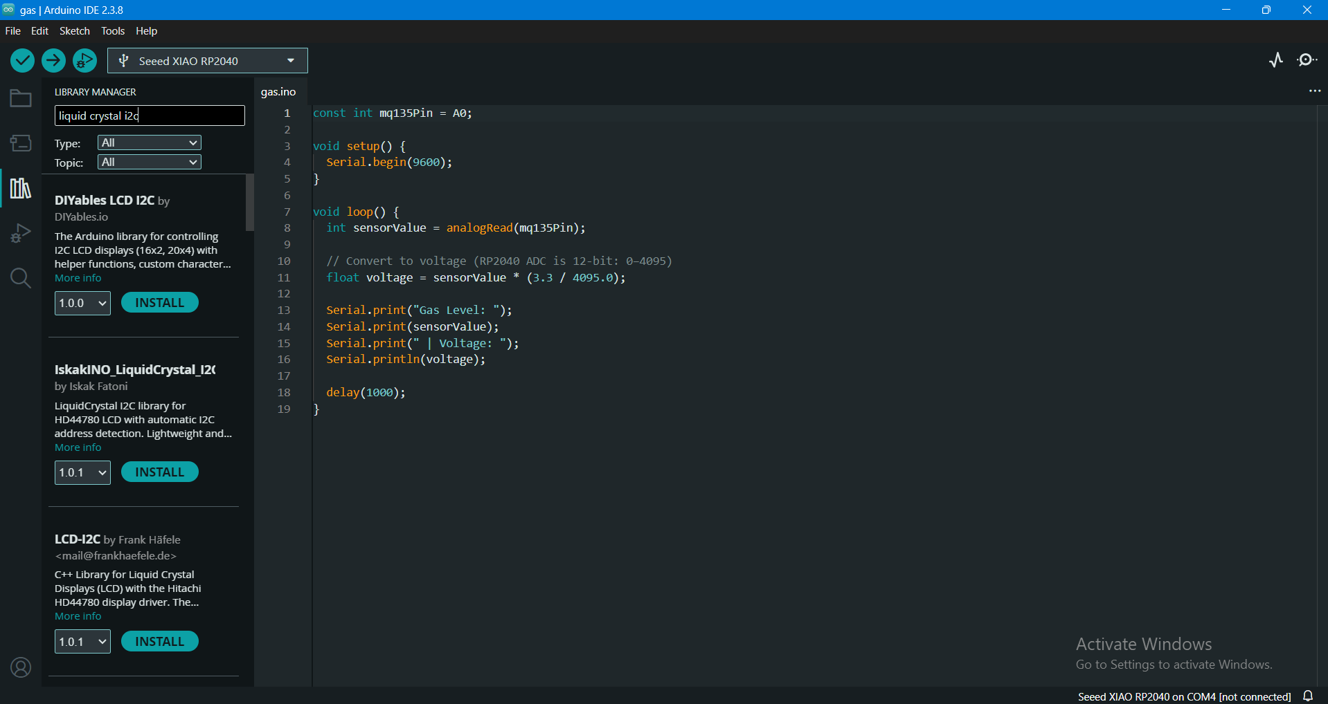
- Search for LiquidCrystal I2C.
- Install the official library release.
Step 2: Understanding I2C Protocol Pins
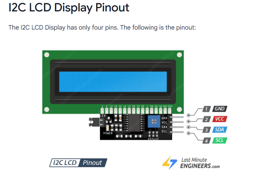
The PCF8574 I2C backpack board converts parallel LCD lines into standard serial communication:
- SDA (Serial Data Line): Transfers bi-directional data bitstreams.
- SCL (Serial Clock Line): Carries clock synchronization pulses generated by the MCU.
Step 3: System Design & Wiring
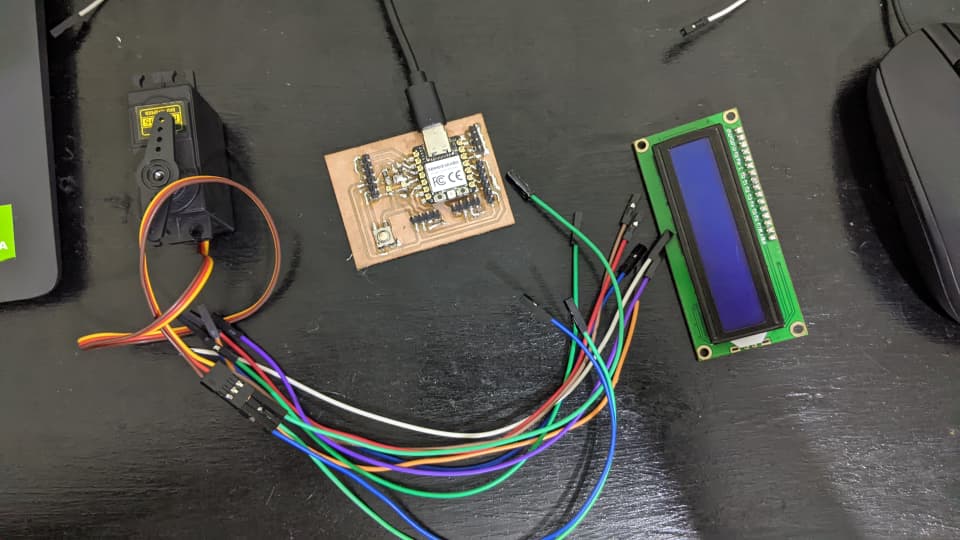
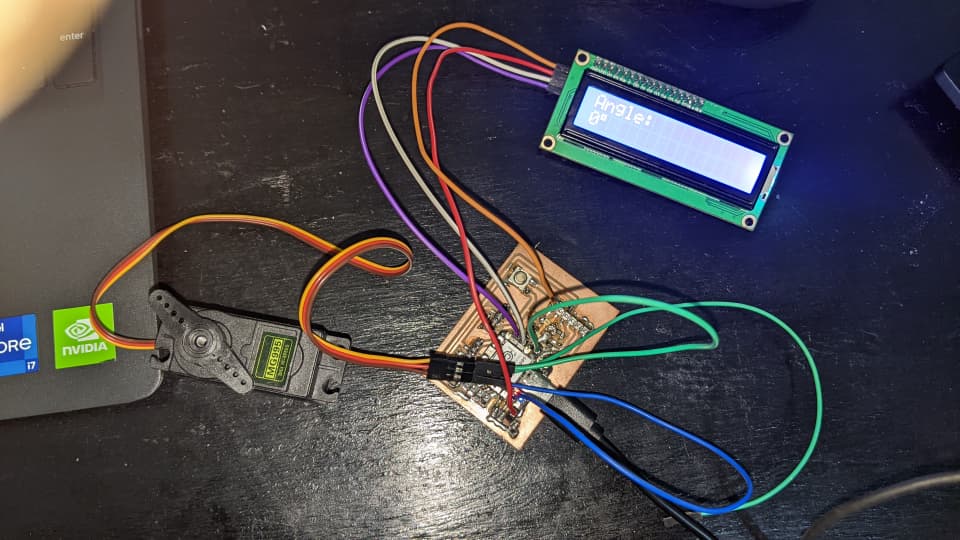
The objective was to actuate the servo through sweep angles while displaying current position data on the LCD in real-time.
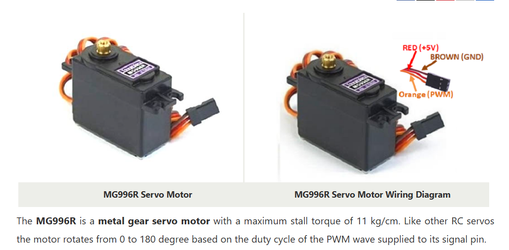
- Servo Connections: Signal connected to PWM pin D2, VCC connected to external 5V, GND connected to common system ground.
- I2C LCD Connections: SDA connected to MCU SDA, SCL to MCU SCL, VCC to 5V, GND to common ground.
Step 4: Power Considerations & Isolation
Inductive loads like servo motors draw sudden current spikes during motor startup. Powering the motor directly from the MCU 3.3V/5V pin caused supply voltage dips that brown-out reset the RP2040 core.
Solution: Powered the SG90 servo motor from an external regulated 5V power bus (ESP32 Vin pin) while tying all ground leads together to establish a shared ground reference plane.
Step 5: Arduino Servo + LCD Control Code
#include <Wire.h>
#include <LiquidCrystal_I2C.h>
#include <Servo.h>

LiquidCrystal_I2C lcd(0x27, 16, 2);
Servo myServo;

void setup() {
  lcd.init();
  lcd.backlight();

  myServo.attach(D2);

  lcd.setCursor(0, 0);
  lcd.print("System Ready");
  delay(1000);
}

void loop() {
  for (int angle = 0; angle <= 180; angle += 10) {
    myServo.write(angle);

    lcd.clear();
    lcd.setCursor(0, 0);
    lcd.print("Angle: ");
    lcd.print(angle);
    lcd.print((char)223); // Degree symbol

    delay(500);
  }
}
Project 1 Video Demonstration
PROJECT 2: LDR SENSOR + BUZZER + LED INTERACTIVE SYSTEM
Understanding Light Dependent Resistors & Voltage Dividers
An LDR's resistance drops significantly under bright light and increases in dark conditions. Because microcontrollers read voltage rather than raw resistance, the LDR is paired with a fixed 10kΩ resistor to form a voltage divider network:
Vout = (R_fixed / (R_LDR + R_fixed)) * Vcc
System Control Logic
The system samples continuous analog voltages from the divider network at pin A3 and executes conditional logic based on calibrated ambient light thresholds:
- Uncovered LDR (Ambient Light): Analog reading remains above threshold → Buzzer and LED remain OFF.
- Covered/Touched LDR (Low Light): Analog reading falls below threshold → Triggers Digital High outputs to activate LED and Piezo Buzzer simultaneously.
Hardware Setup & Connections
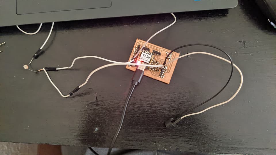
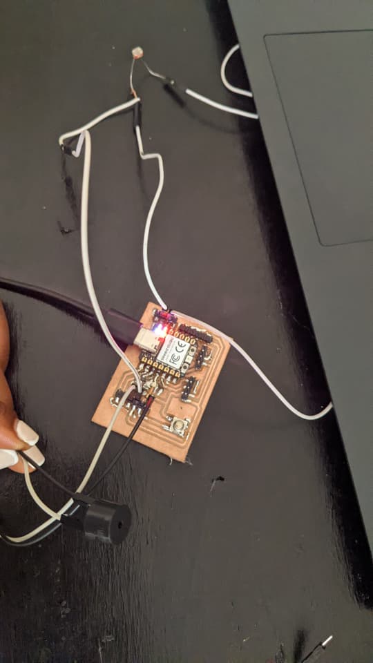
- LDR Voltage Divider: LDR connected to 3.3V rail, 10kΩ resistor to GND, mid-point connected to pin A3.
- Indicator LED: Anode (+) wired to pin D1, Cathode (-) to GND via 220Ω current-limiting resistor.
- Piezo Buzzer: Positive terminal to pin D2, Negative terminal to GND.
Step-by-Step Sensor Calibration
Because ambient room lighting varies depending on the working environment, calibration via Serial Monitor is required before setting fixed software triggers:
- Opened Arduino Serial Monitor at 115200 baud rate.
- Recorded raw 12-bit ADC values under normal ambient ambient light (~3000).
- Recorded raw values when covering/touching the LDR sensor face (~1000).
- Selected a decision threshold halfway between ambient and covered values (Threshold = 2000).
Project 2 Arduino Control Code
const int ldrPin = A3;
const int ledPin = D1;
const int buzzerPin = D2;

int threshold = 2000; // Calibrated midpoint value

void setup() {
  pinMode(ledPin, OUTPUT);
  pinMode(buzzerPin, OUTPUT);
  Serial.begin(115200);
}

void loop() {
  int ldrValue = analogRead(ldrPin);
  Serial.print("LDR Raw Value: ");
  Serial.println(ldrValue);

  if (ldrValue < threshold) {
    // Sensor covered (Touch event detected)
    digitalWrite(ledPin, HIGH);
    digitalWrite(buzzerPin, HIGH);
  } else {
    // Ambient light condition
    digitalWrite(ledPin, LOW);
    digitalWrite(buzzerPin, LOW);
  }

  delay(100);
}
Project 2 Video Demonstration
Final Assembly & Custom PCB Integration
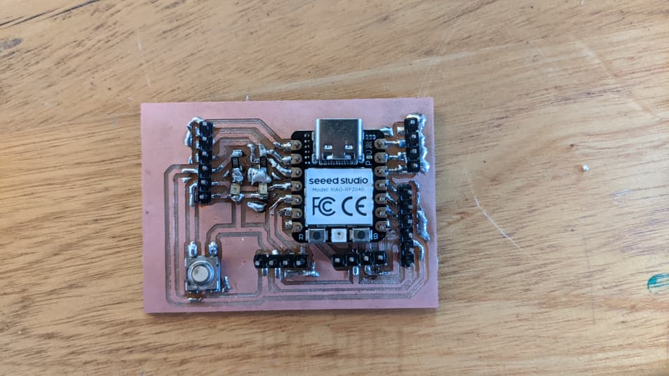
Mounted the XIAO RP2040 onto header sockets on my custom milled development board, routing all output lines directly through accessible header pins:
Challenges & Solutions
1. Servo Instability & Microcontroller Brownouts
Cause: High current draw during servo sweeps overloaded internal board regulators, triggering CPU brownouts.
Solution: Isolated the servo VCC line onto an external 5V supply and tied grounds together.
2. Unstable Analog LDR Readings
Cause: High frequency noise in raw ADC samples caused output flickering near threshold limits.
Solution: Implemented a 100ms sampling delay loop and set clear hysteresis bounds around calibrated sensor values.
3. I2C LCD Display Blank / No Characters
Cause: Incorrect default I2C hex address in constructor code.
Solution: Ran an I2C scanner sketch to confirm the display backpack address was 0x27.
What I Learned
- Understanding how output actuators convert digital logic and PWM signals into precise physical movement.
- Managing power distribution to isolate sensitive microcontrollers from inductive noise created by motors.
- Distinguishing between constant duty-cycle PWM signals and continuous analog voltage measurements.
- Designing closed-loop systems that translate analog inputs directly into multi-output alert actions.
- Systematic debugging procedures for isolating hardware power failures versus software communication bugs.