// Week 07
Computer-Controlled Machining
Introduction
This week focuses on "Making Something Big." I decided to design and fabricate a custom ergonomic small chair[cite: 1, 2]. The motivation behind this design was personal utility: I needed a portable, sturdy seat specifically for use while cooking in the kitchen[cite: 1, 2]. The design follows a press-fit assembly philosophy, allowing it to be sturdy without requiring mechanical fasteners or glue[cite: 1, 2].
Objectives
Group Assignment
- Complete the lab's safety training for the large-format CNC machine[cite: 1, 2].
- Test runout, alignment, and fixturing methods[cite: 1, 2].
- Determine optimal speeds, feeds, and toolpaths for the specific material used[cite: 1, 2].
Group Assignment Documentation →[cite: 1, 2]
Individual Assignment
- Design a large-scale object (at least 1m x 1m nested)[cite: 1, 2].
- Demonstrate 2D design development for CNC production[cite: 1, 2].
- Document the CAM toolpath generation and the machining process[cite: 1, 2].
- Assemble and finish the final product[cite: 1, 2].
Tools & Technologies
1. SolidWorks (Design & Assembly)
I used SolidWorks for the complete 3D modeling and assembly design of the chair[cite: 1, 2]. It allowed me to create parametric sketches, define dimensions accurately, and visualize how all parts fit together before fabrication[cite: 1, 2].
2. Large Format CNC Router
The CNC machine used is capable of machining full plywood sheets[cite: 1, 2]. During operation, safety precautions such as eye protection, hearing protection, and machine supervision were mandatory[cite: 1, 2].
3. 4mm Flat End Mill
A 4mm flat end mill was selected because it provides a good balance between cutting speed and detail accuracy[cite: 1, 2].
Process & Workflow
INDIVIDUAL PROJECT: THE KITCHEN CHAIR
Design Process
In my daily life, I like cooking and wanted a portable, sturdy seat for cooking in the kitchen that also features a modern aesthetic[cite: 1, 2]. I decided to design a kitchen chair that can also serve dual-purpose functionality, such as a cutting board top[cite: 1, 2]. Using SolidWorks, I followed these design steps[cite: 1, 2]:
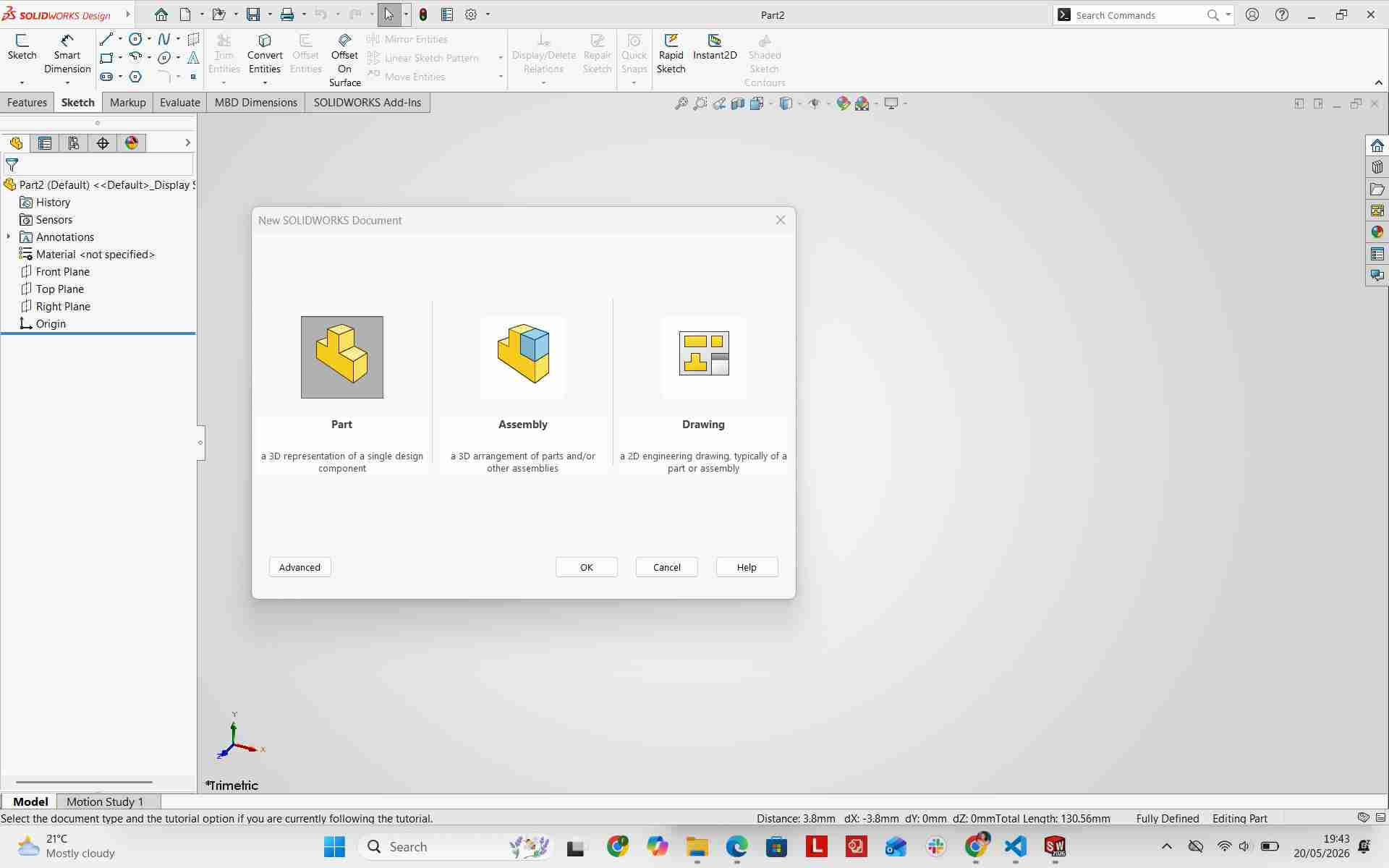
Creating a New Part and Selecting the Front Plane
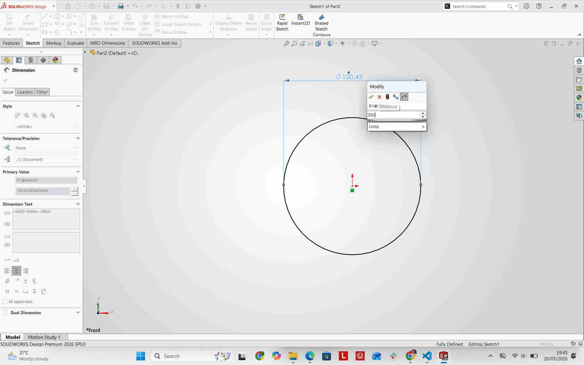
Creating the Circle Sketch for the Seat
I started by creating the seat profile by drawing a circular sketch with a diameter of 350 mm[cite: 1, 2]. The size was selected to make the chair comfortable while remaining compact enough for kitchen use[cite: 1, 2].
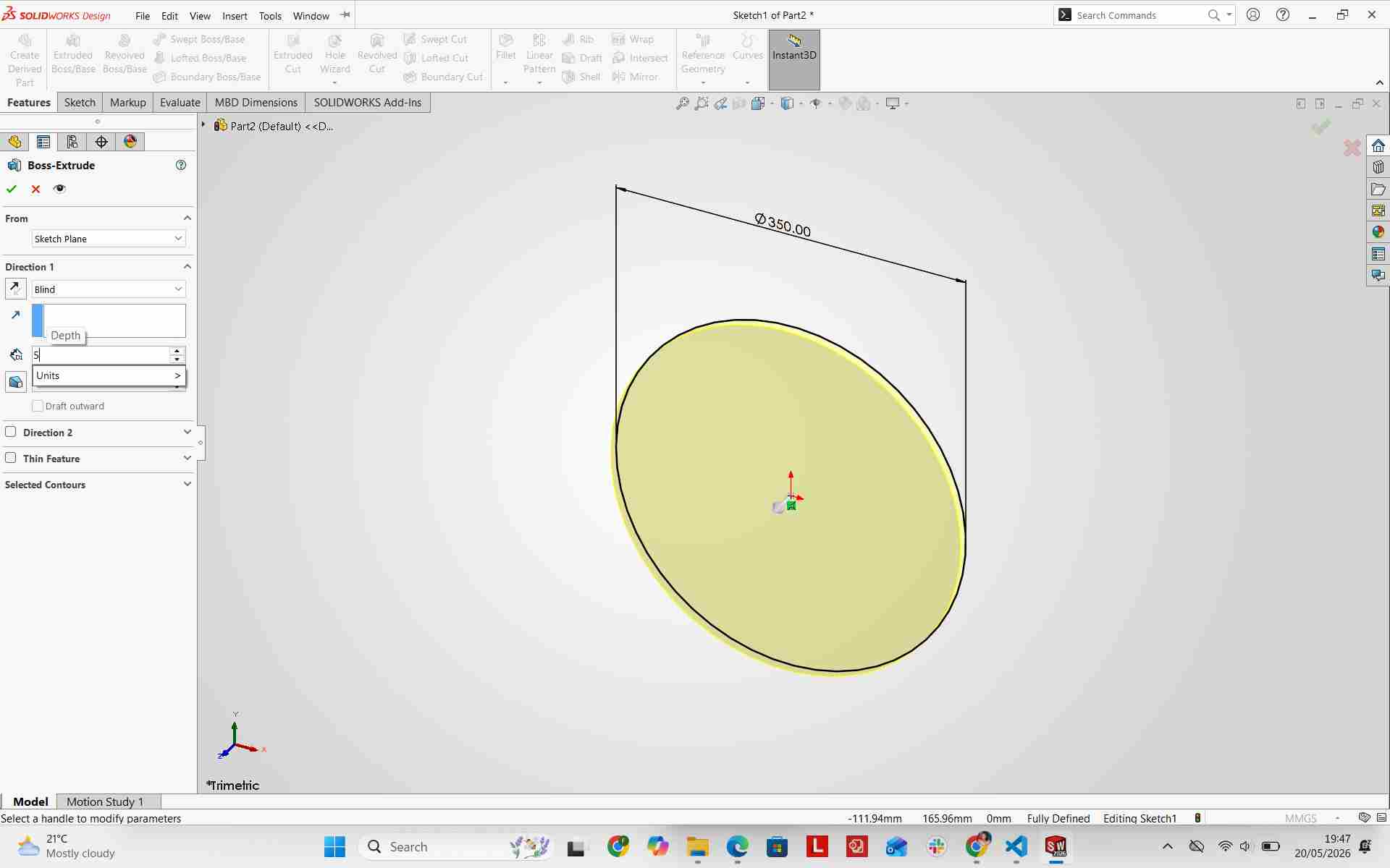
Extruding the Seat
I extruded the seat to 19 mm thickness, matching the plywood thickness used for fabrication[cite: 1, 2]. This provided a solid base for the chair while keeping it lightweight and portable[cite: 1, 2].
Designing the Leg Profile
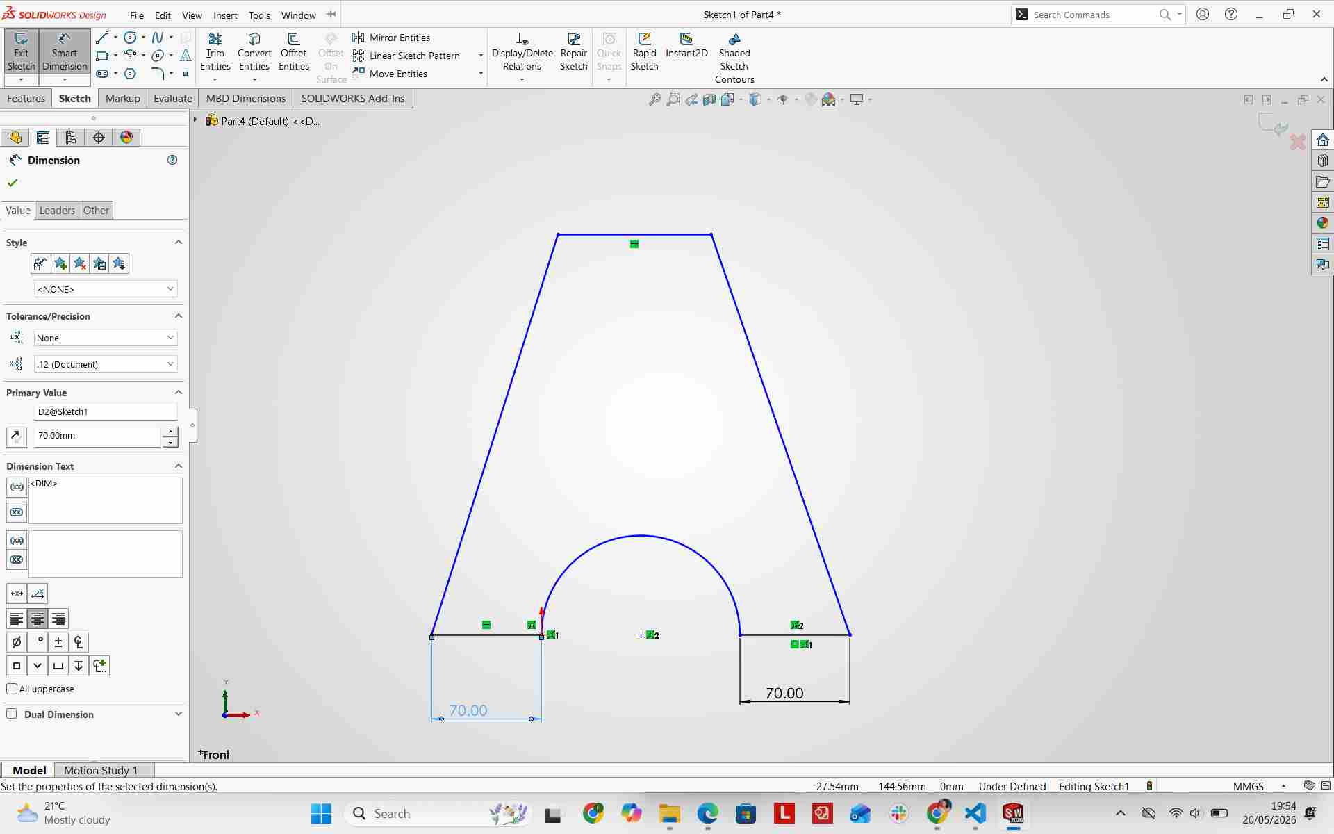
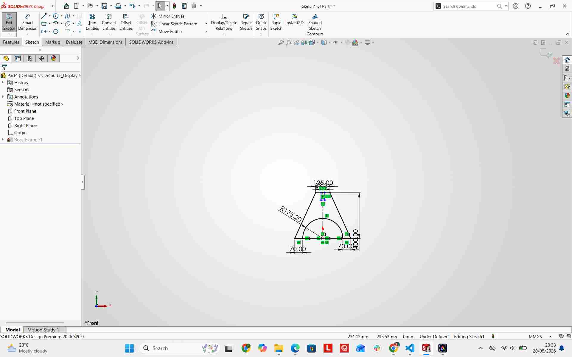
To begin the leg structure, I created a new sketch on the Front Plane[cite: 1, 2]. I drew a circle and power-trimmed the profile to obtain a semi-circular arc matching the seat diameter, adding extended geometry to form the leg support structure[cite: 1, 2].
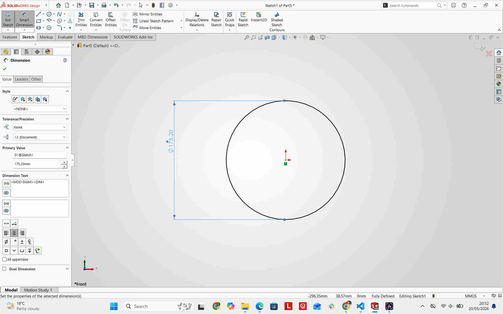
Adding Dimensions to the Leg
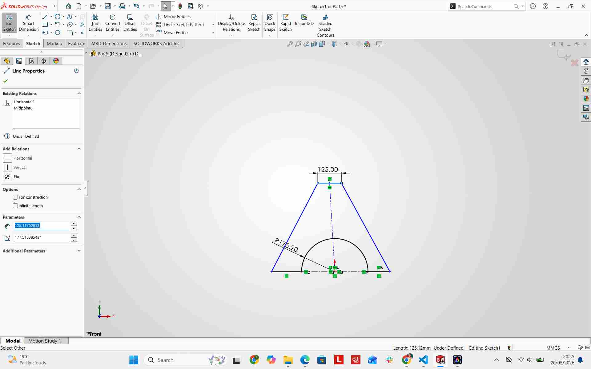
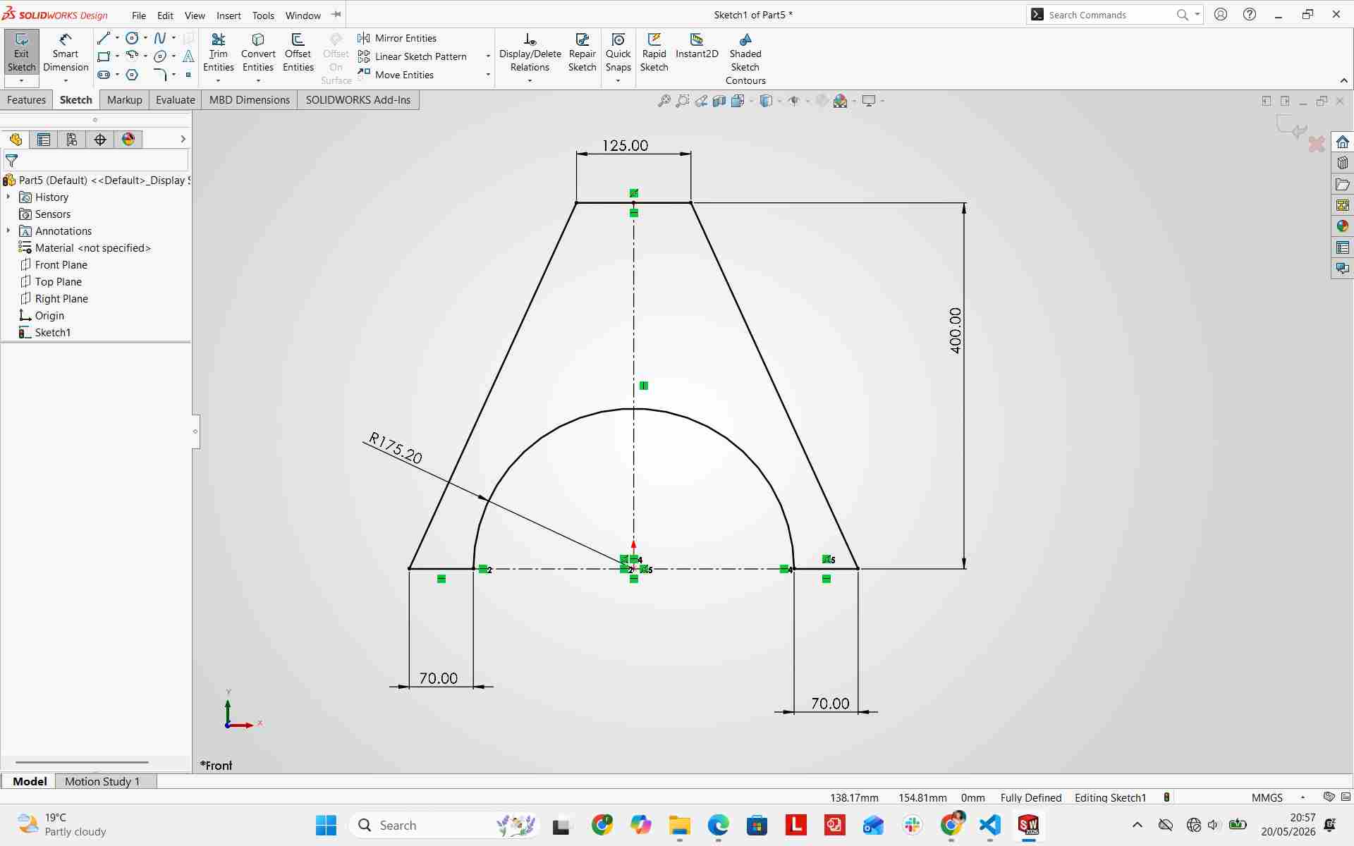
I added dimensions and constraints to the leg sketch to ensure structural stability and proper alignment with the seat[cite: 1, 2].
Extruding the Leg
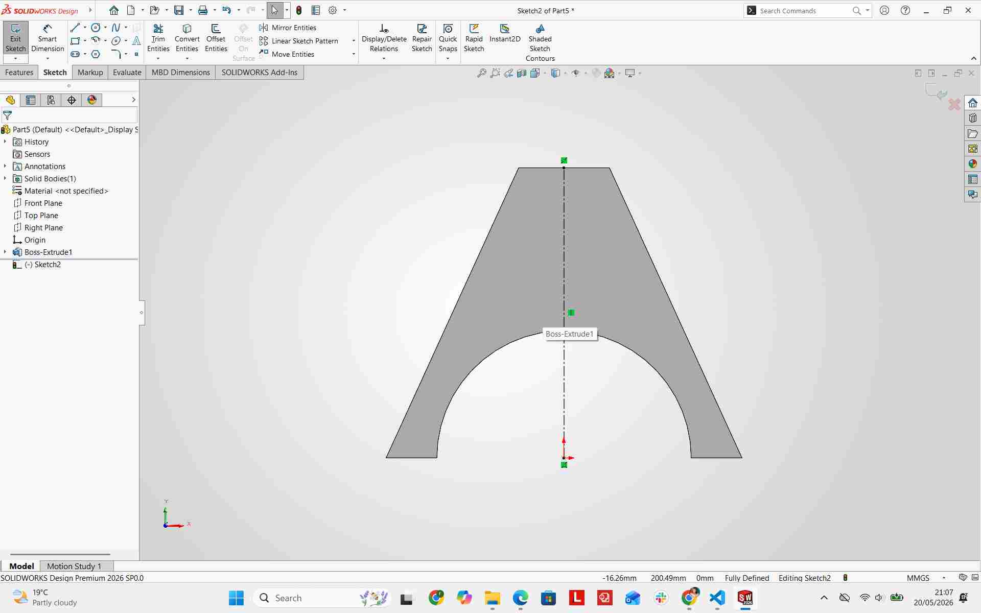
I used the Extruded Boss/Base feature to give the leg a thickness of 19 mm, matching the physical material thickness[cite: 1, 2].
Adding Press-Fit Joints using Extruded Cut
To enable screw-free assembly, I created a slot at the top of the leg[cite: 1, 2]. The slot width was set to 19 mm to allow the seat and legs to join tightly using friction[cite: 1, 2]. I then added corresponding insertion slots on the seat component to receive the leg tabs[cite: 1, 2].
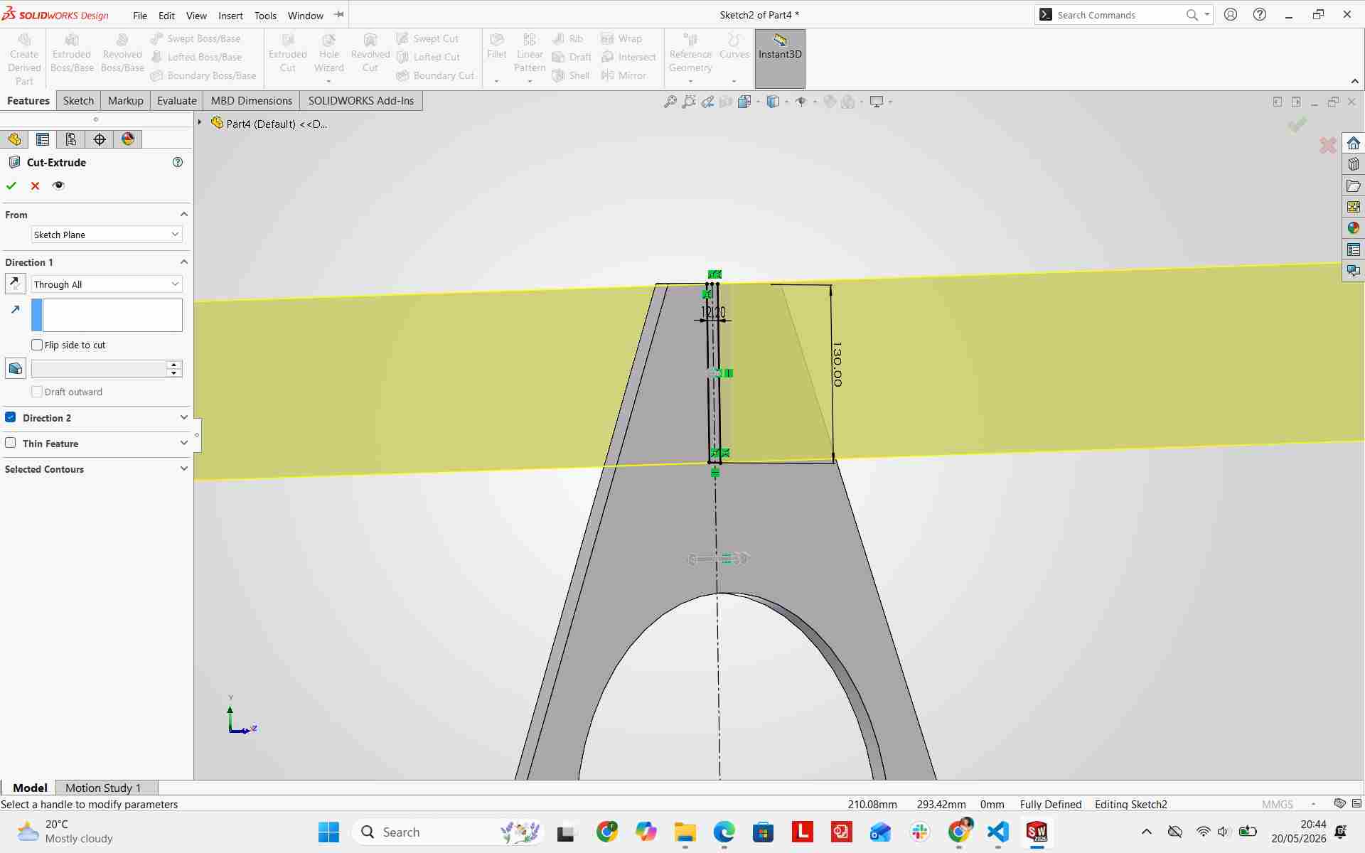
Final Design of First Leg
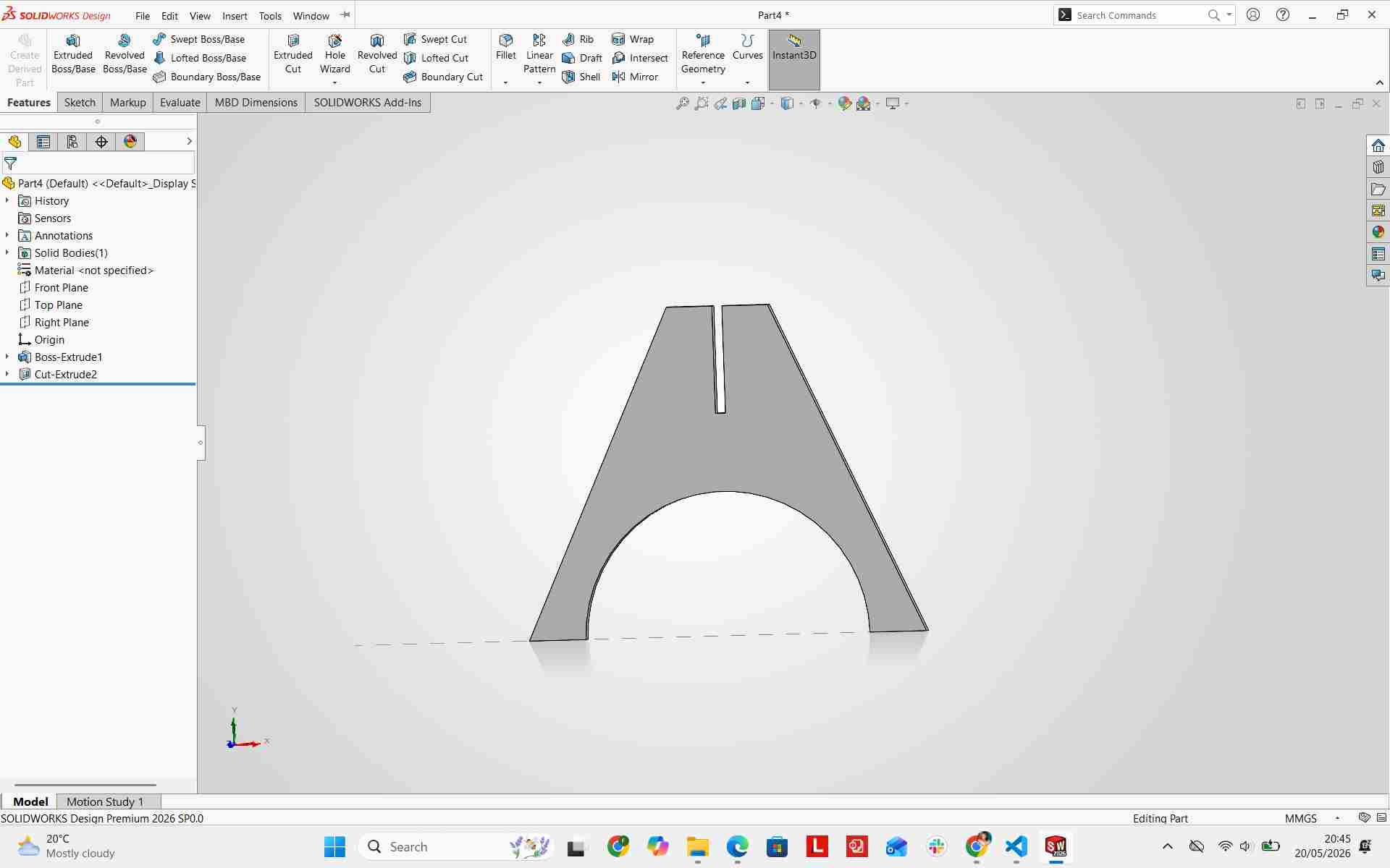
Extrude Cut Insertion for Second Leg
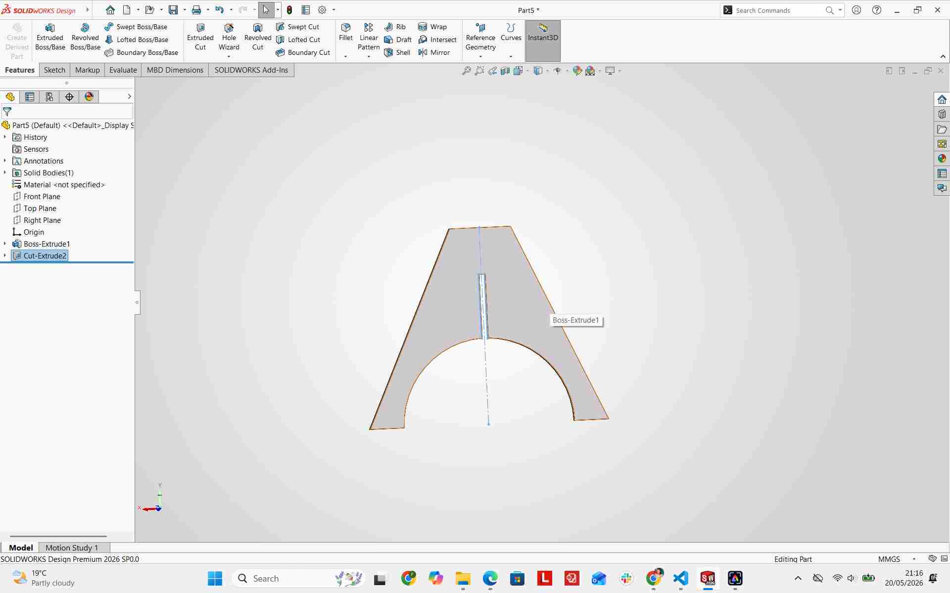
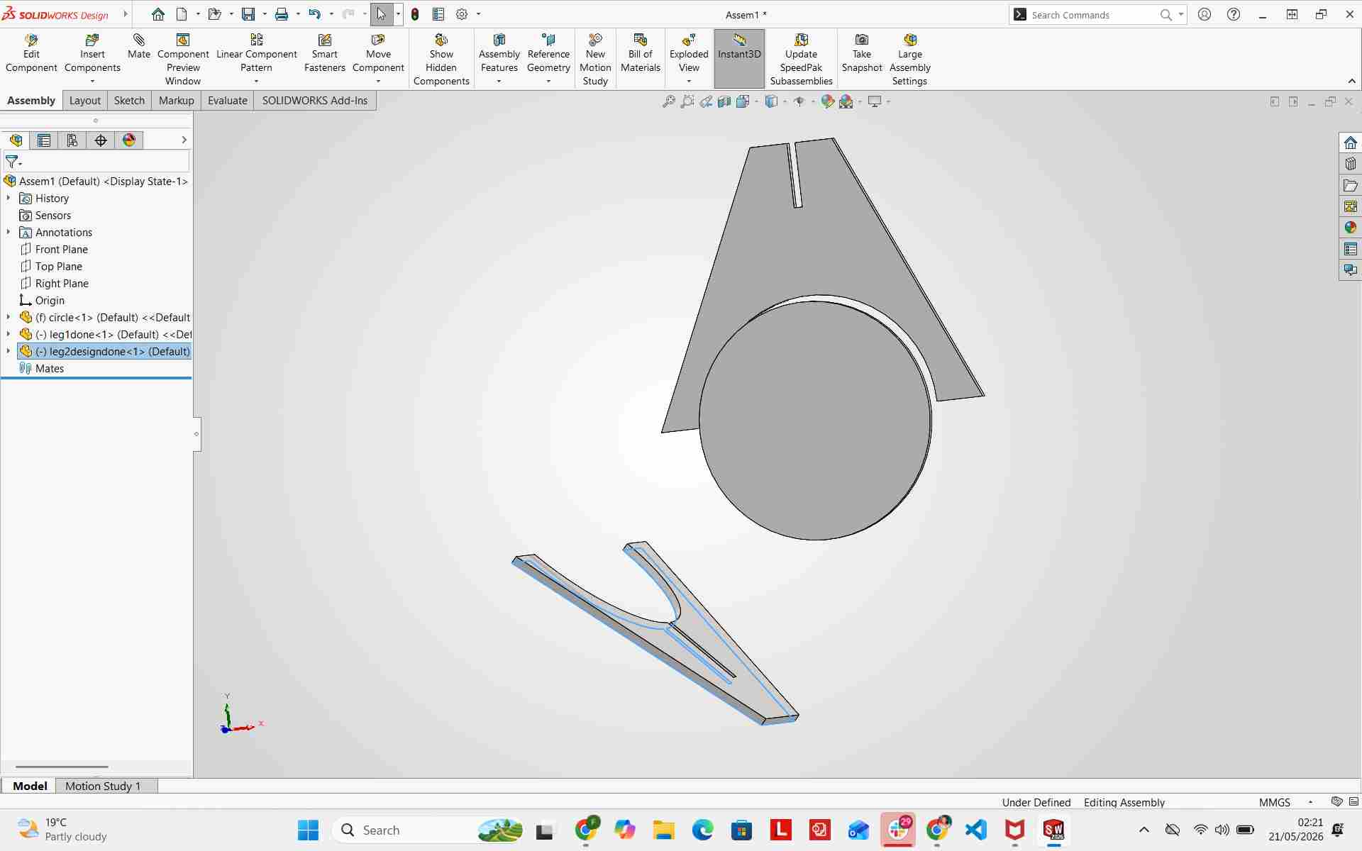
For the interlocking cross-leg base structure, the second leg incorporated an inverted slot section[cite: 1, 2]. I applied an extruded cut to form the interlocking notch on Leg 2 as well as the corresponding socket on the seat underside[cite: 1, 2].
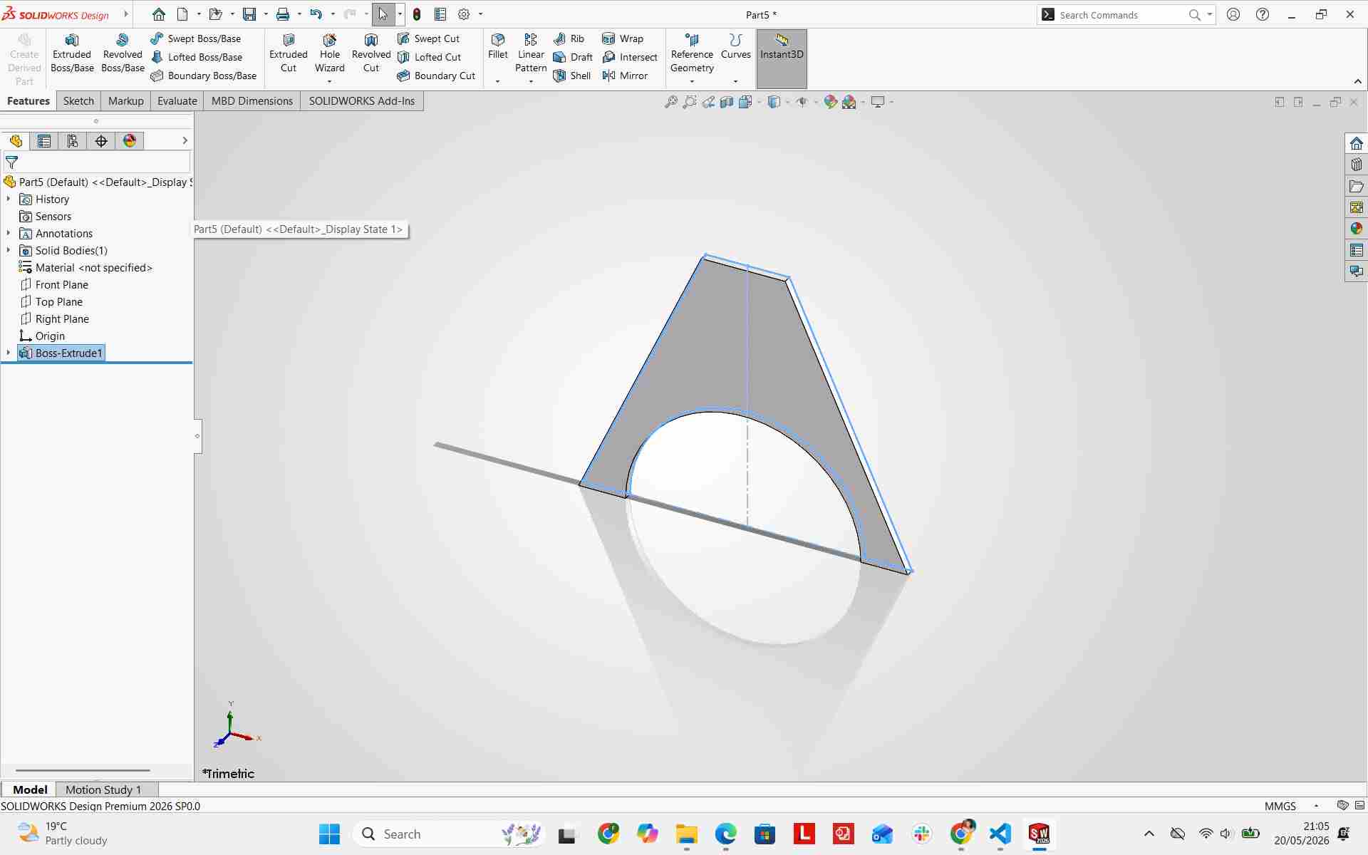
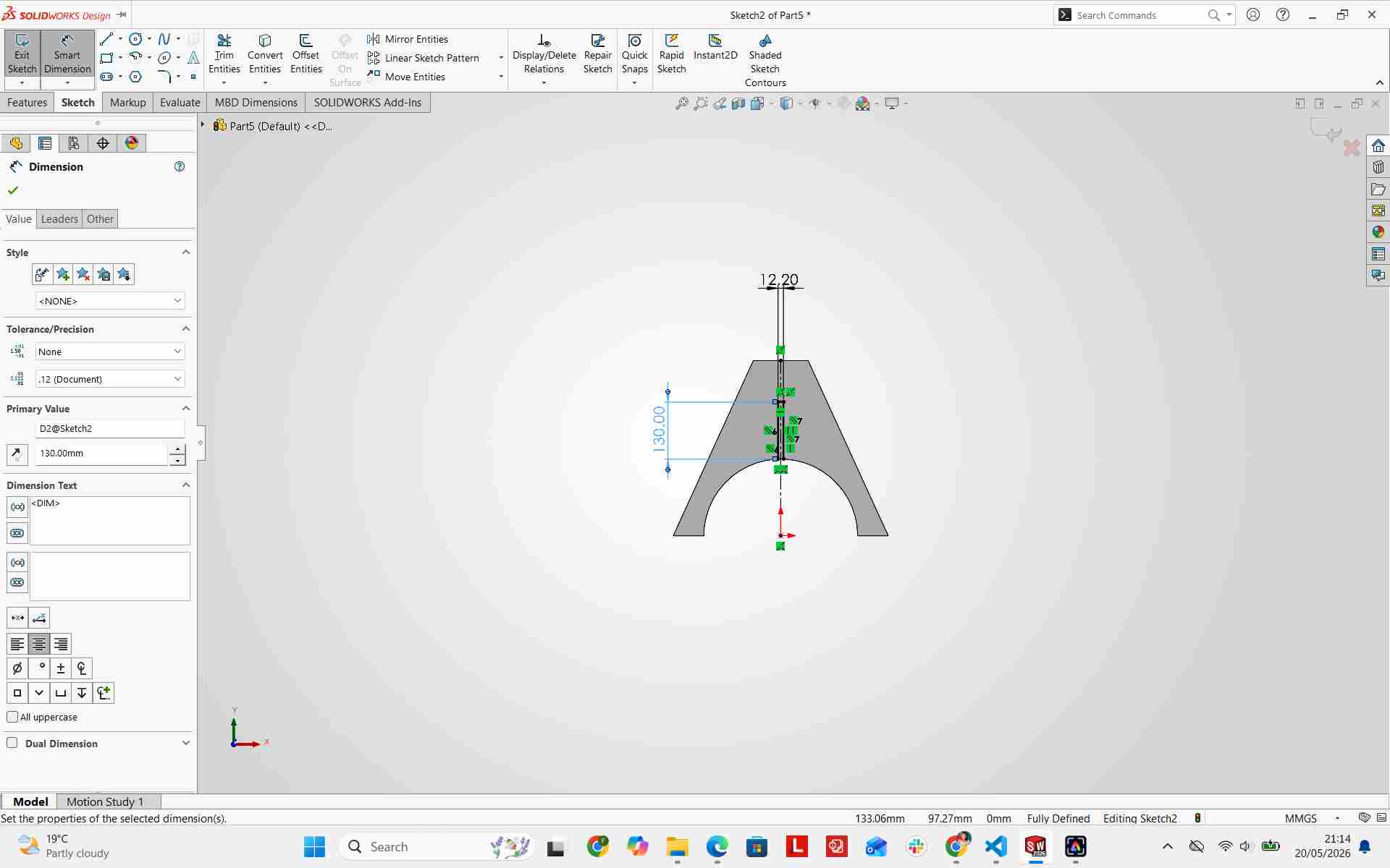
Final Design of Second Leg
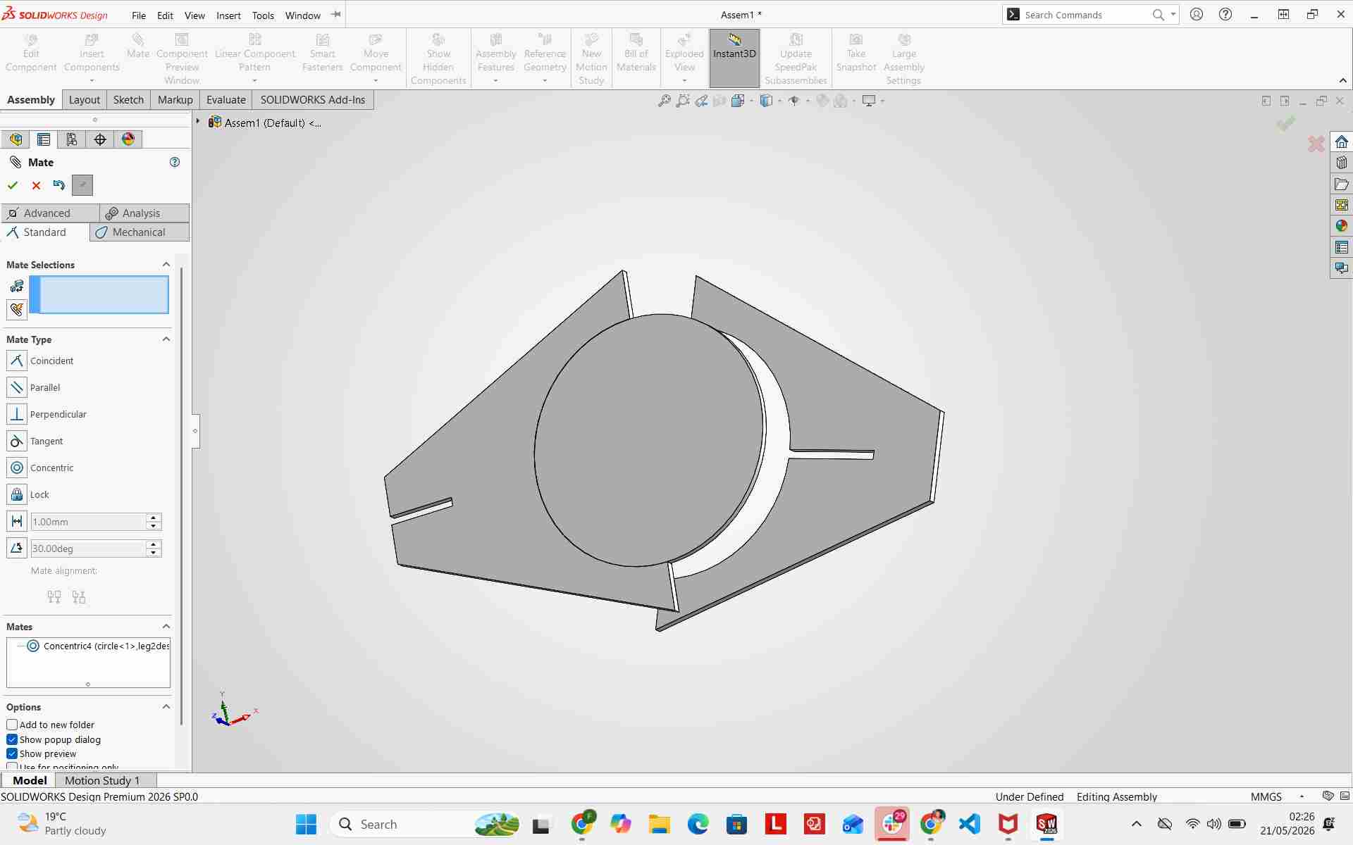
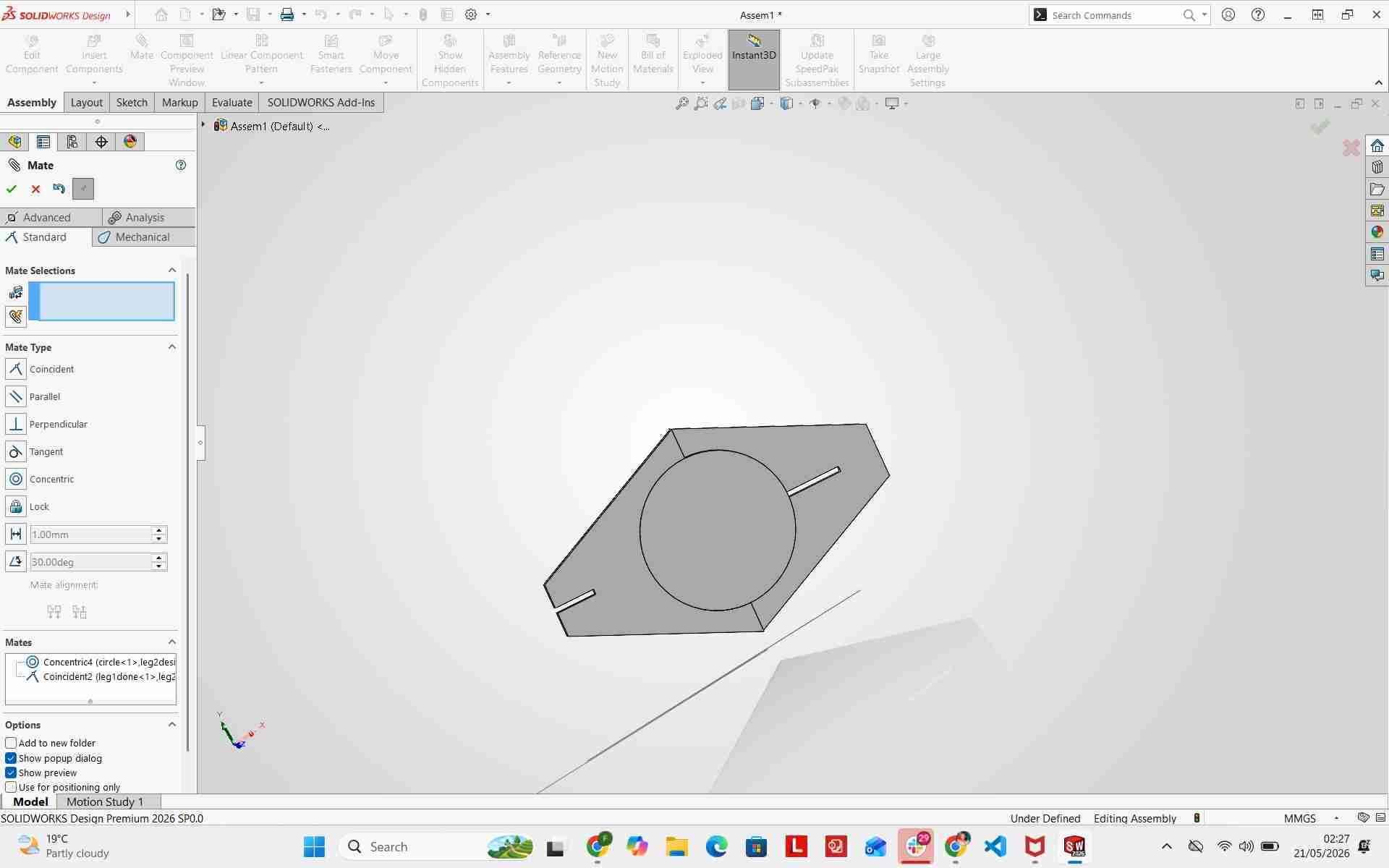
Assembling Chair Components
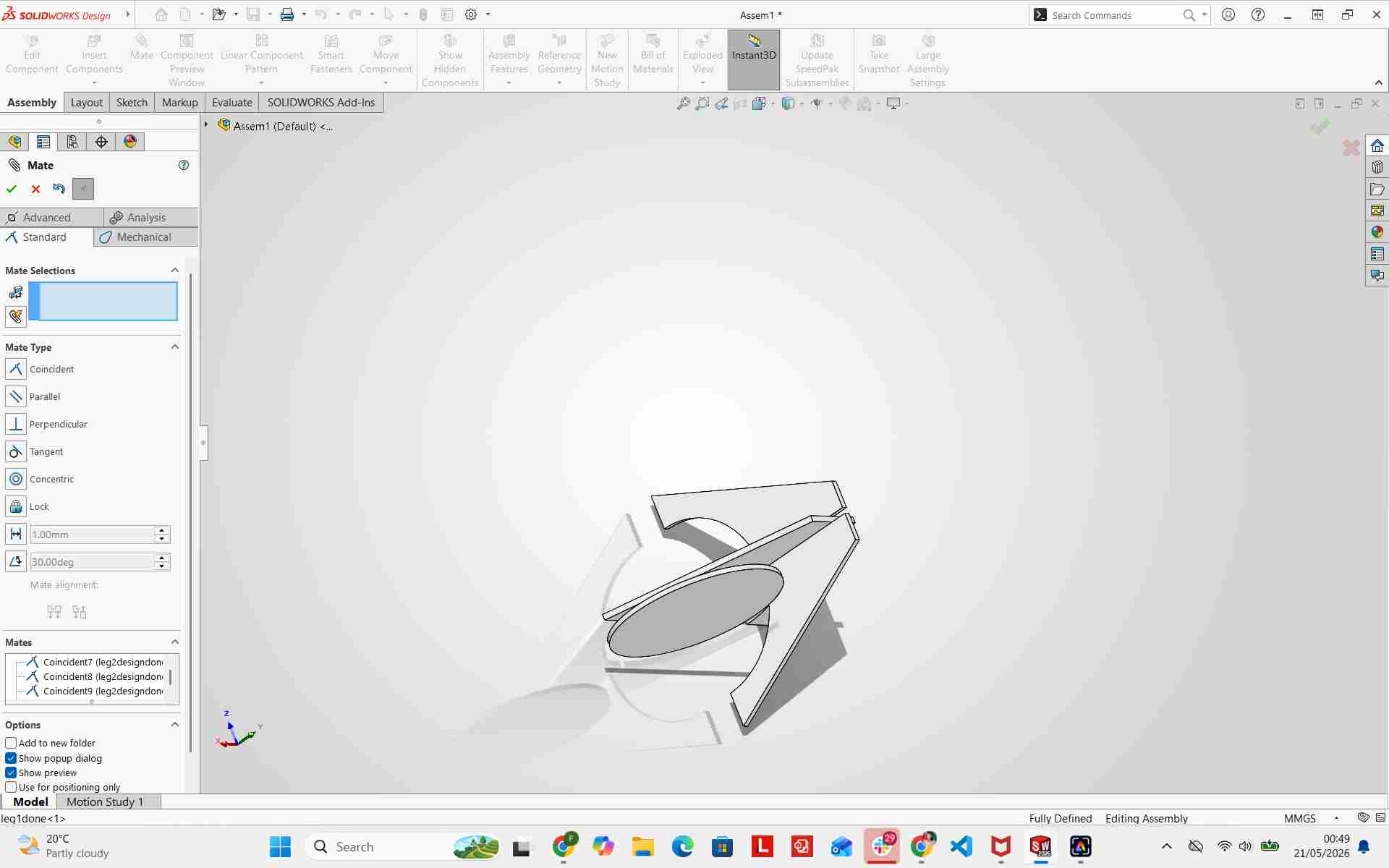
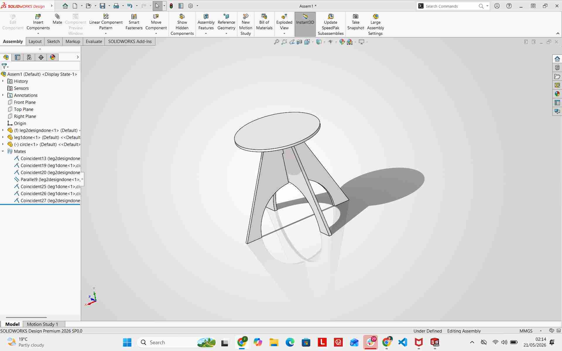
I assembled all components in a SolidWorks Assembly file[cite: 1, 2]. By applying mate relations between the seat and leg components, I verified physical fit, clearances, leg stability, and overall chair height before moving to CAM production[cite: 1, 2].
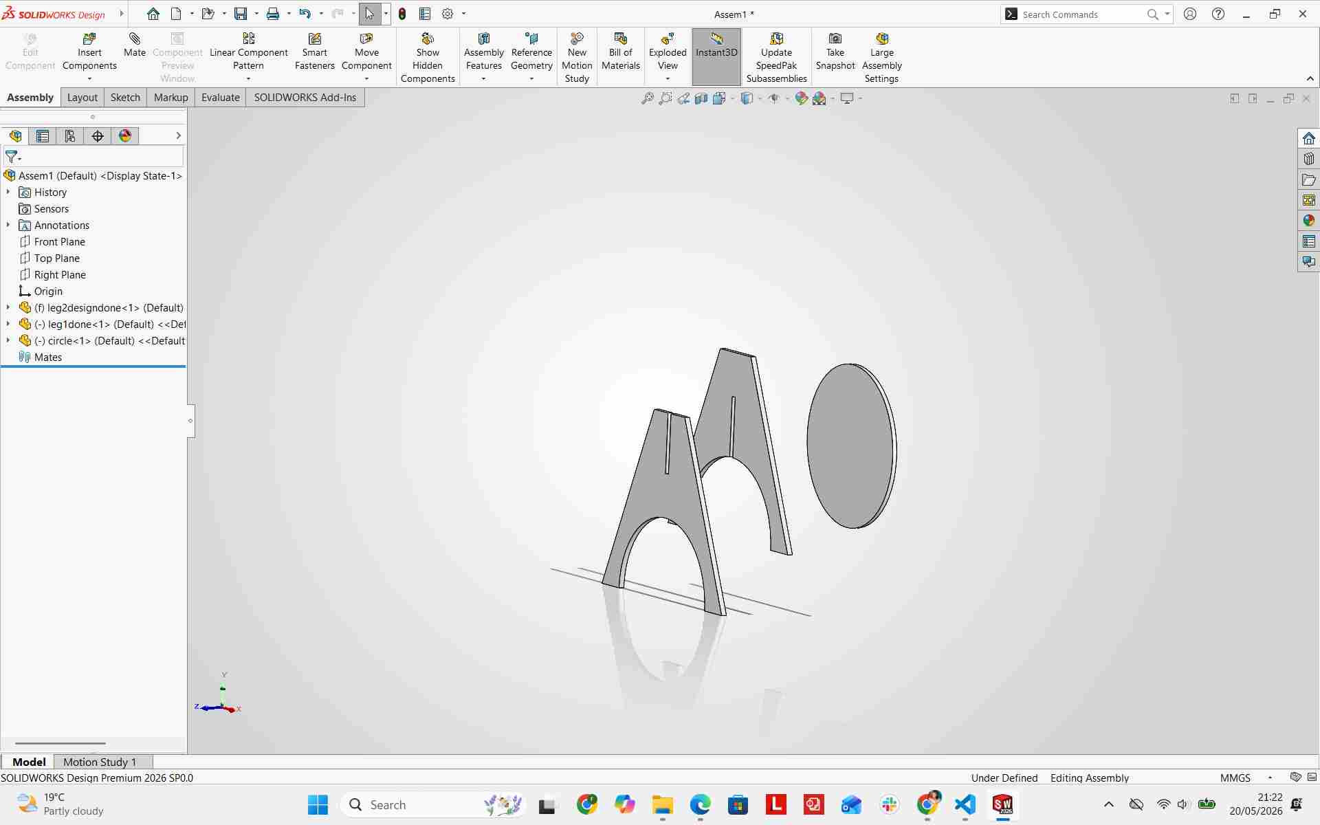
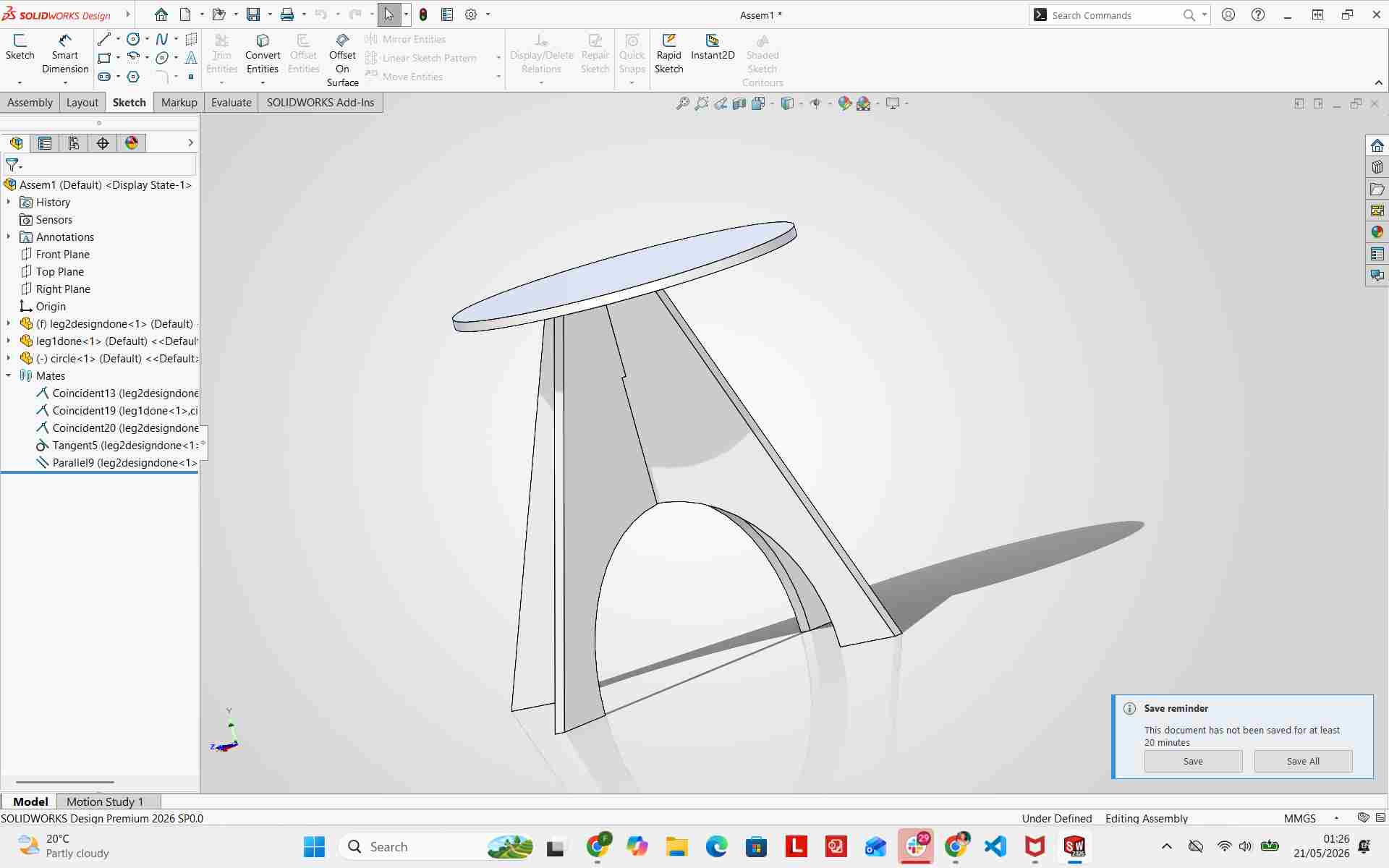
Final Design of Chair
Cutting Board Top Integration
I verified the optional cutting board top fitting over the seat surface, ensuring multi-functional usability in kitchen contexts[cite: 1, 2].
CNC Stool Production & Machining Process
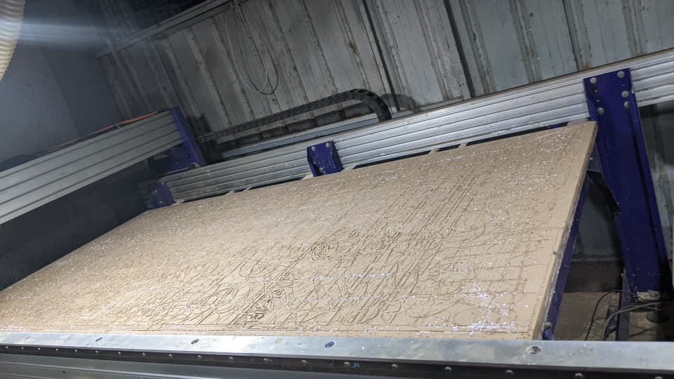
Large-format CNC router machine bed used to mill the stool components[cite: 1, 2].
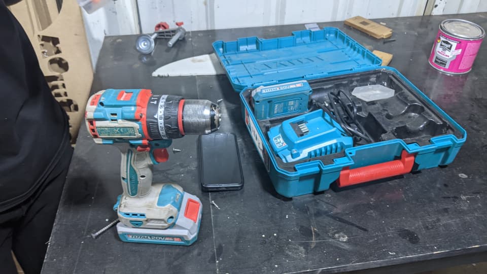
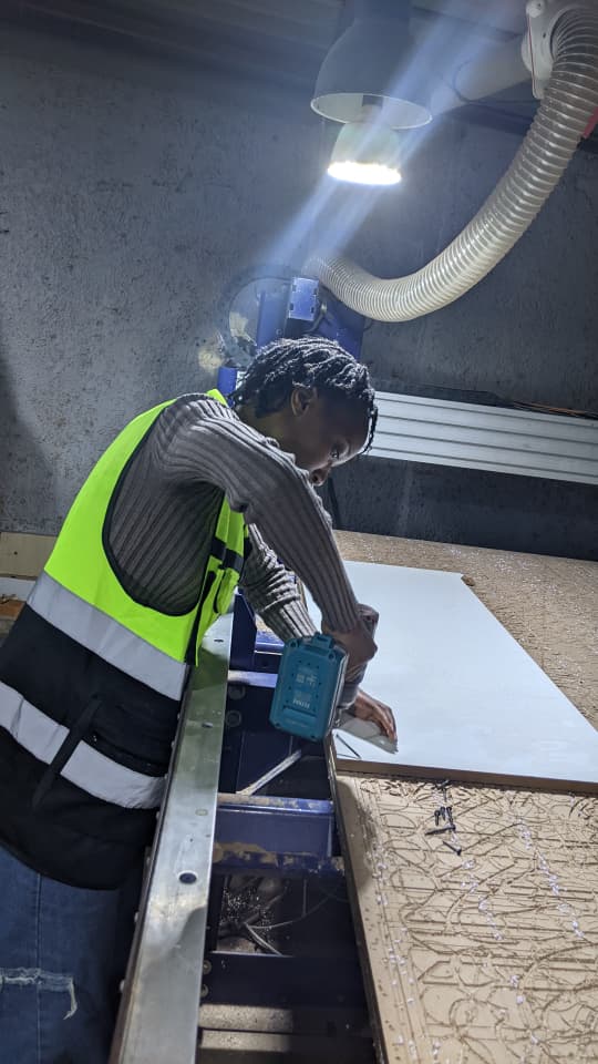
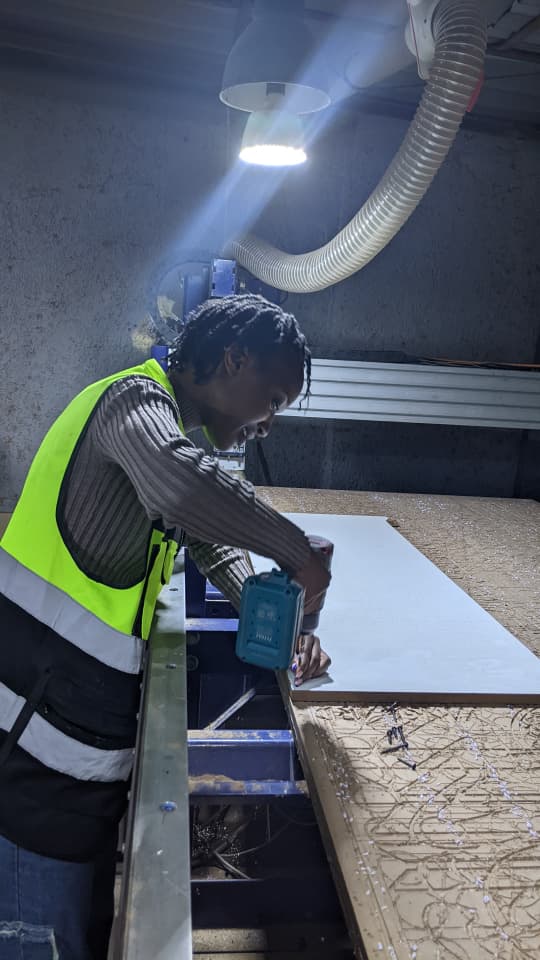
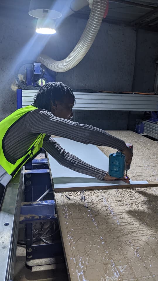
Securing stock material down with a power drill to prevent board movement during high-speed cutting passes[cite: 1, 2].
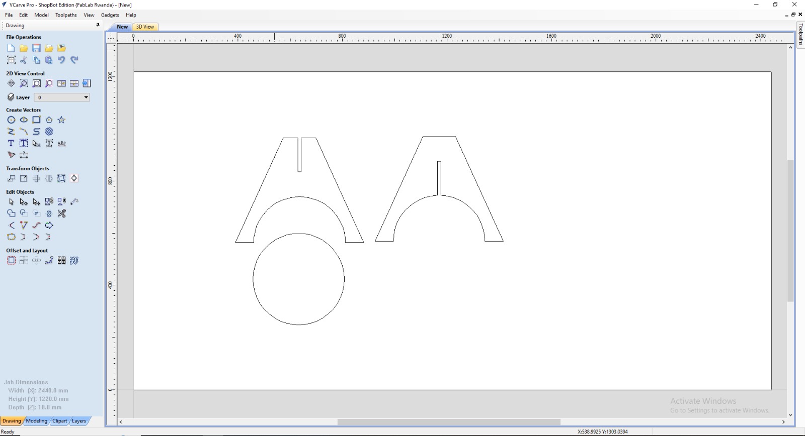
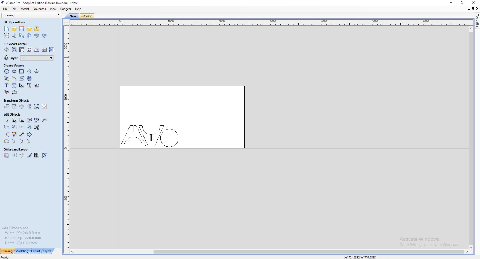
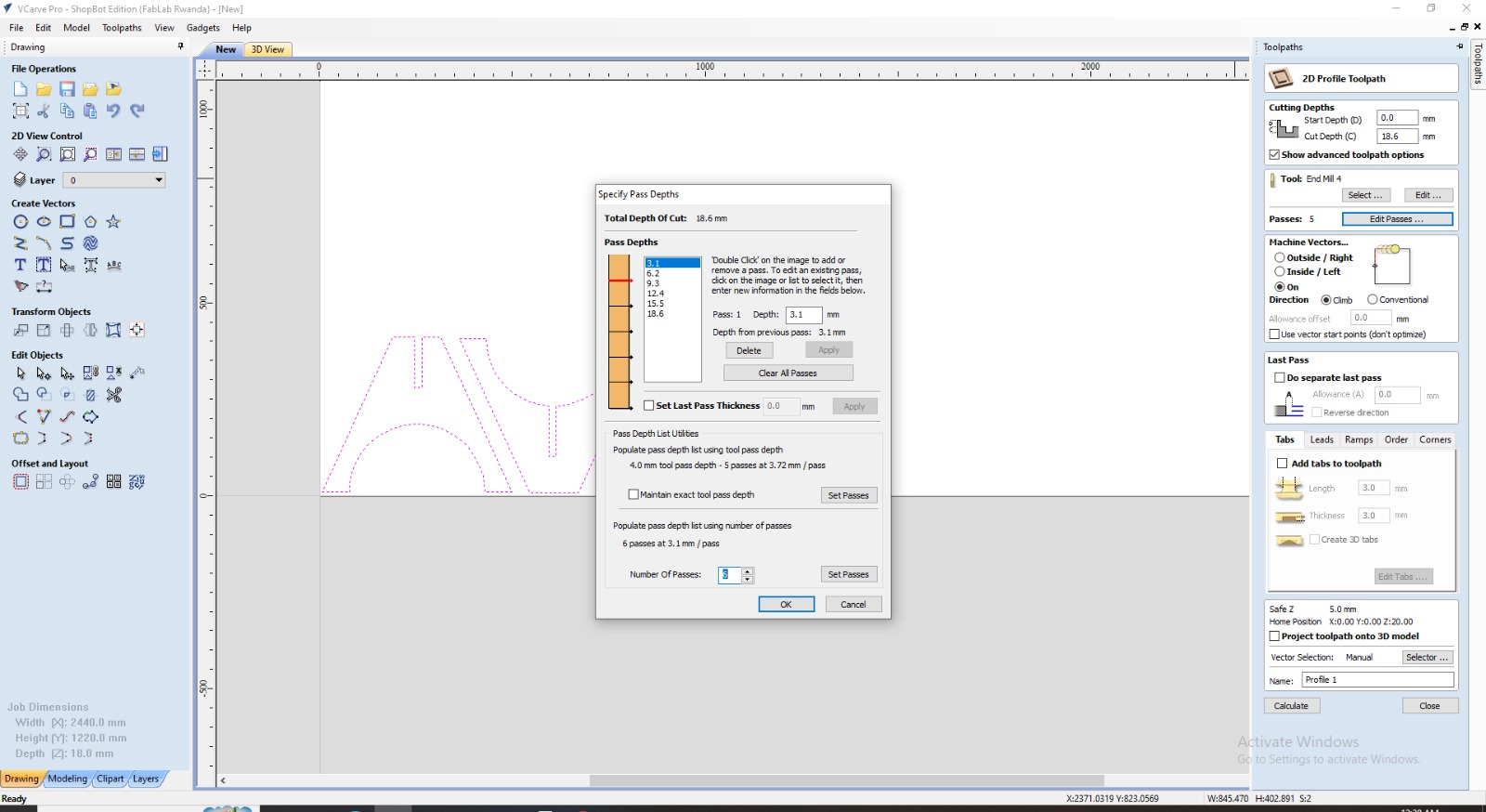
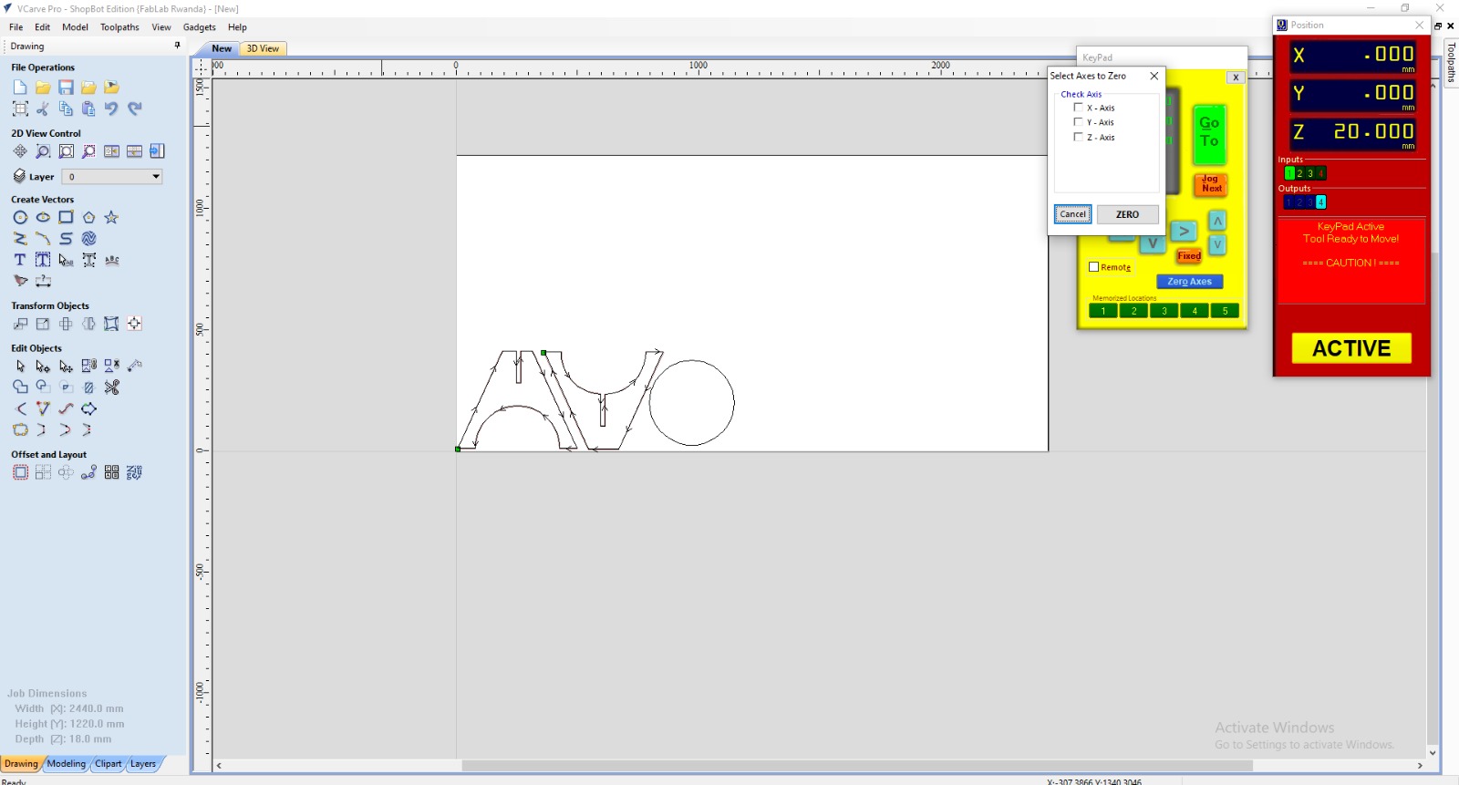
VCarve CAM interface used to prepare toolpaths and nesting layouts[cite: 1, 2].
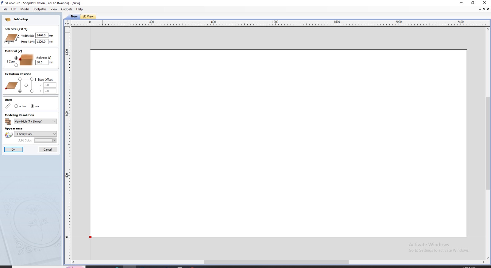
Importing vector profiles of the three chair components into VCarve[cite: 1, 2].
Nesting parts efficiently on the material sheet to optimize stock utilization[cite: 1, 2].
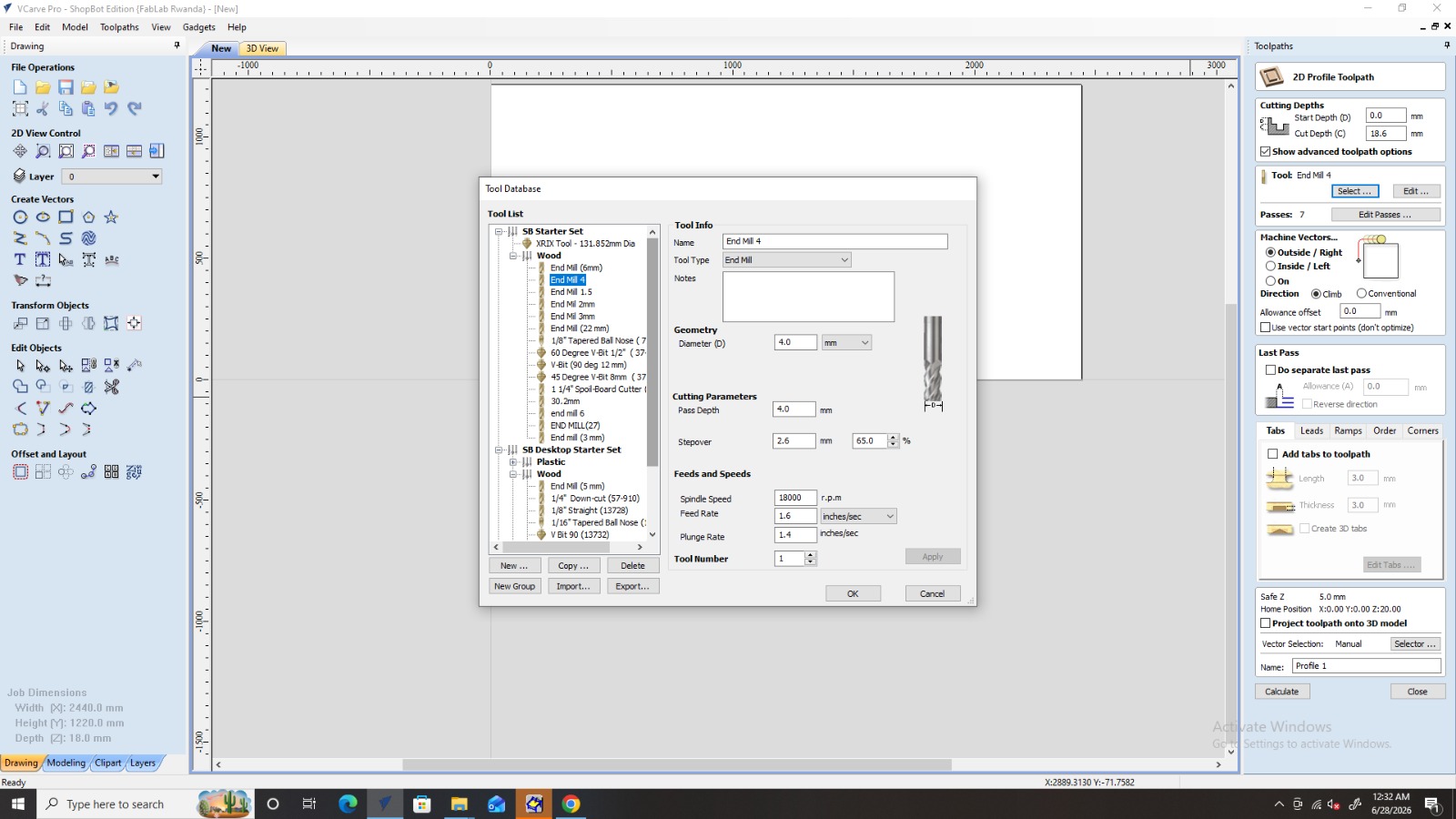
Configuring profile cutting settings: cutting 3.1mm depth per pass across 6 total passes using an outside vector profile path[cite: 1, 2].
Setting spindle speed to 18,000 RPM and feed rate to 1.6 inches/sec with a 4mm flat end mill[cite: 1, 2].
Fixing laminated stock onto the router bed and clamping edges securely[cite: 1, 2].
Installing the 4mm end mill bit into the collet and tightening securely with wrenches[cite: 1, 2].
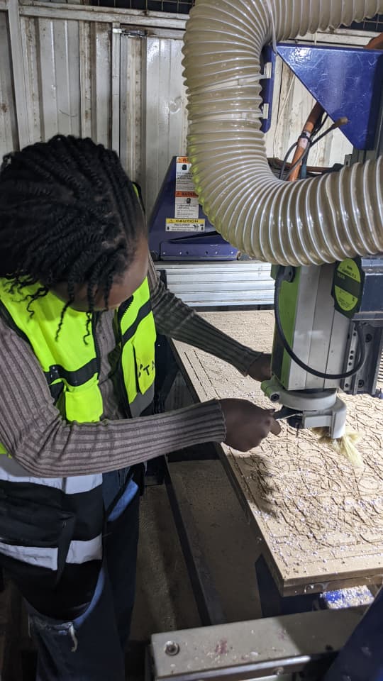
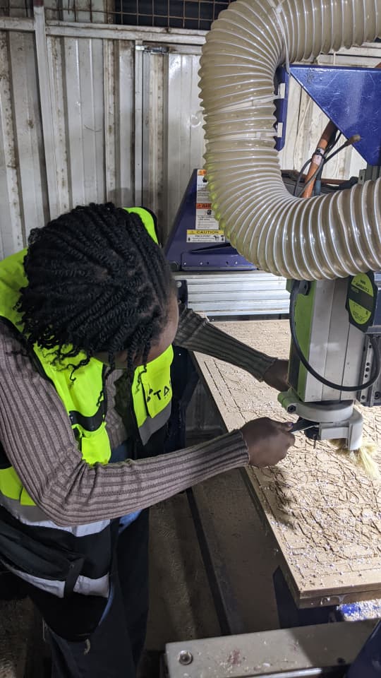
Zeroing axis origins and initializing toolpaths[cite: 1, 2].
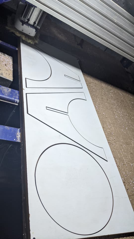
Executing CNC profiling job to cut clean outer boundaries and slot geometries[cite: 1, 2].
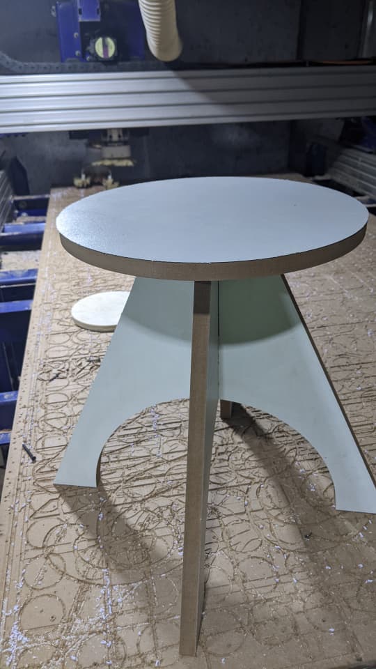
Sliding the two machined leg pieces together along their central press-fit notches[cite: 1, 2].
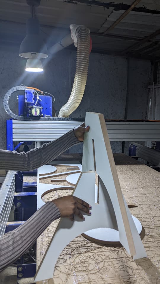
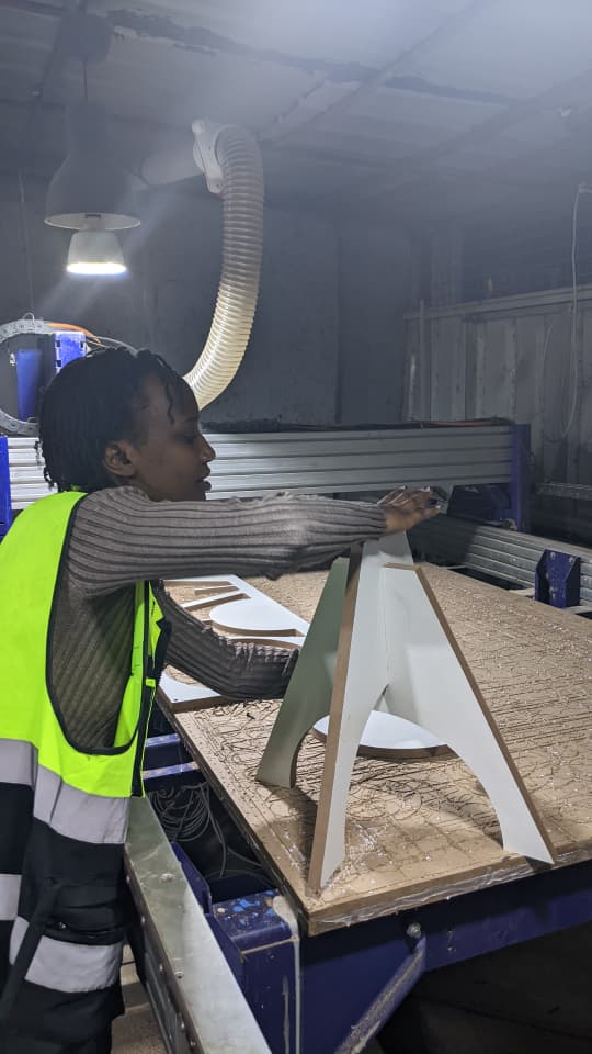
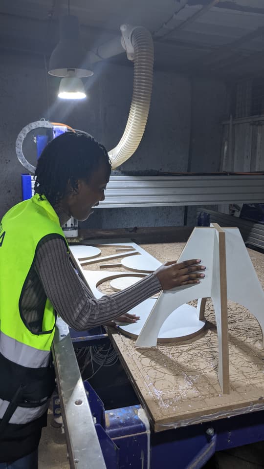
Aligning top seat slots with leg tabs and pressing into position[cite: 1, 2].
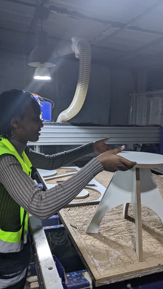
Final completed CNC press-fit ergonomic kitchen stool[cite: 1, 2].
Challenges & Solutions
- Material Thickness Variation: Nominal 19mm stock measured 19.3mm locally[cite: 1, 2]. Initial test joints were overly tight, which I resolved by hand-filing 0.15mm off inner slot faces for smooth press-fit engagement[cite: 1, 2].
- Optimizing sheet nesting orientation to minimize raw material waste[cite: 1, 2].
- Calibrating feed rates to eliminate heat buildup and edge burning in sharp corner passes[cite: 1, 2].
What I Learned
- Designing for large-format CNC machining where material load tolerances and structural integrity govern design choices[cite: 1, 2].
- Applying dog-bone and T-bone corner reliefs to permit full clearance for square mating tabs in CNC slotted joints[cite: 1, 2].
- Safely operating heavy CNC machinery and implementing reliable board fixturing methods[cite: 1, 2].