// Week 05
3D Scanning & Printing
Introduction
In Week 05, I explored additive manufacturing using 3D printing and 3D scanning. The goal was to understand the design rules of our 3D printer and create an object that could not be easily made subtractively.
Task/Assignment
Group Assignment
- Test the design rules for your 3D printer(s)
- Document your work on the group work page and reflect on your individual page what you learned about characteristics of your printer(s)
Individual Assignment
- Design, document and 3D print an object (small, few cm3, limited by printer time) that could not be easily made subtractively
- 3D scan an object (and optionally print it)
Tools & Technologies
1.a Autodesk Fusion
Fusion is a 3D CAD software used for modeling and engineering design. I used it to design my finger rings.
Download Fusion: Download Autodesk Fusion
1.b solidworks
Solidworks is a 3D CAD software used for modeling and engineering design. I used it to design Cat Toy.
2. 3D Printer
We used our lab FDM 3D printer to print PLA material.
3. 3D Scanner
We used a 3D scanning device to digitize a physical object.
Group Assignment
Testing Printer Design Rules
We printed a test file to check:
- Overhang angles
- Bridging distance
- Clearance between parts
- Minimum wall thickness
Observing Results
We measured which overhang angle printed successfully without support and identified the minimum clearance our printer can handle.
Reflection
I learned that each printer has limitations. Understanding these characteristics helps to design printable models.
Individual Assignment
3D DESIGN AND PRINTING
During this assignment I fouced on learning how 3D printer works with different design software files. I n the beginning I used Fusion 360 to design Fidget ring i have succesfull designed it but Unfortunaltely I forget to save files to which I can 3D print and at that moment i changed pc and lost all the files and software also, as the new PC I got was not compatible with Fusion 360, so I had to use Solidworks to design the small ball inside a Ribbon sphere which was ball inside open ball. In this documentation I am going to share with you all the trial with both software and the fails and successes I had during this week on section of 3D prining and 3D scanning.
First Trial: Design FIDGET RING using Fusion 360
To make design possible I first downloaded Fusion 360 software and installed it on my computer. I used the tutorial video to learn how the different between subtractive and additive design. After understanding how to design subtractively/additively from the tutorial. I designed fidget rings with curved geometry and inner patterns containing internal curves and decorative cutouts. You can find the tutorial video here:
Difference between Subtractive and Additive Design.Download and Install Fusion
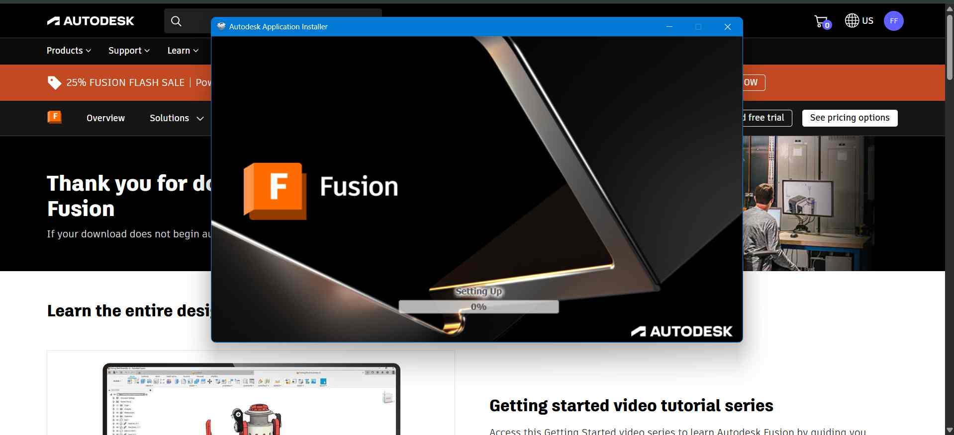
Downloading this software wasn't an easy process. I tried different browsers many times and after some time I managed to download a free 30 days trial, but I met with different challenges during the process. I downloaded this software three times and installed it three times due to the challenges faced during design.
I asked one of my architect friends who has a student license to Autodesk (Alexandre) to help me get access because I thought it might have different features not found in the free trial.
After signing in with student access, I downloaded Autodesk Fusion and installed it on my computer.
Autodesk Fusion Download
Designing the Finger Rings
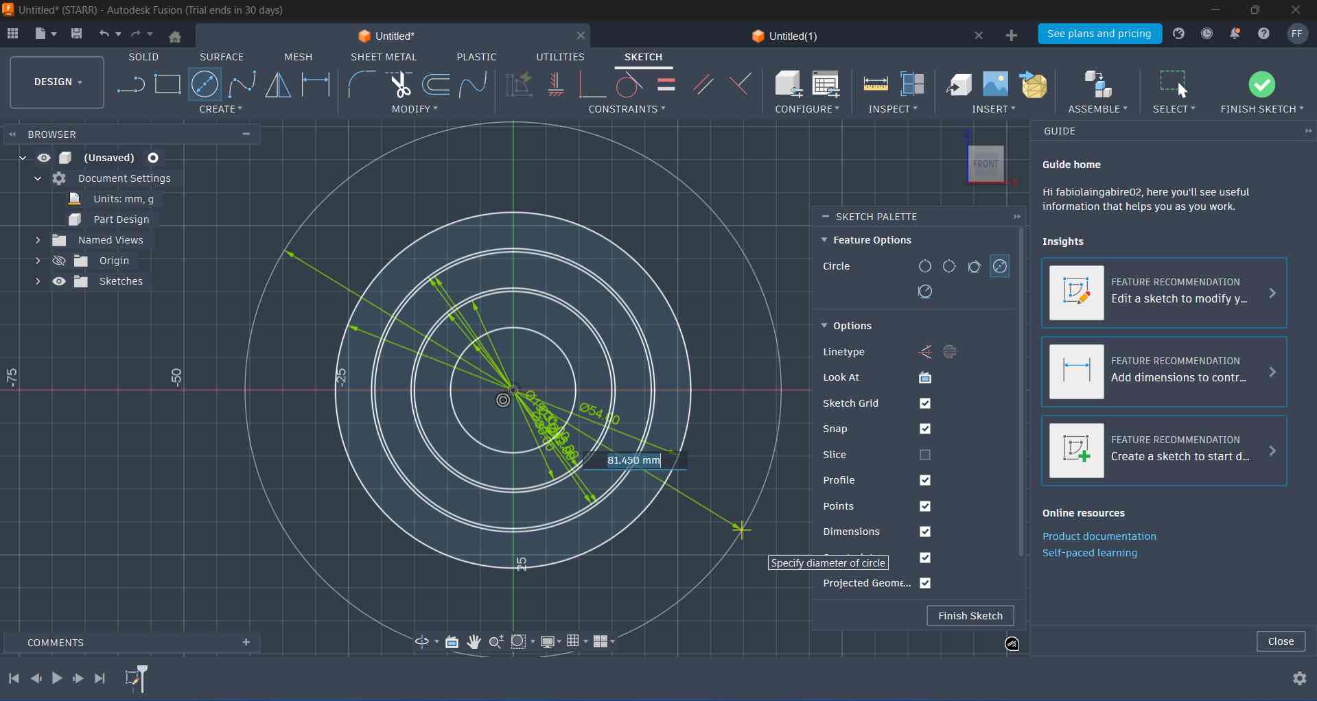
I created a new project and named it "COMPLETE Ring" after understanding how to design subtractively/additively from the tutorial. I designed fidget rings with curved geometry and inner patterns containing internal curves and decorative cutouts.
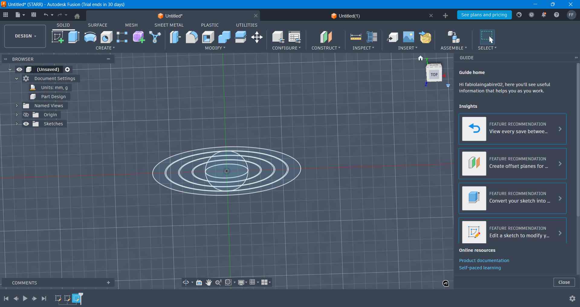
- First, I created an internal circle with a 19 mm diameter, added a second one with 31 mm, followed by 32 mm, 42 mm, 43 mm, 54 mm, 55 mm, and the last one at 66 mm which has curved hollow sections.
- Added a center rectangle with a width of 19 mm and a length of 66 mm.
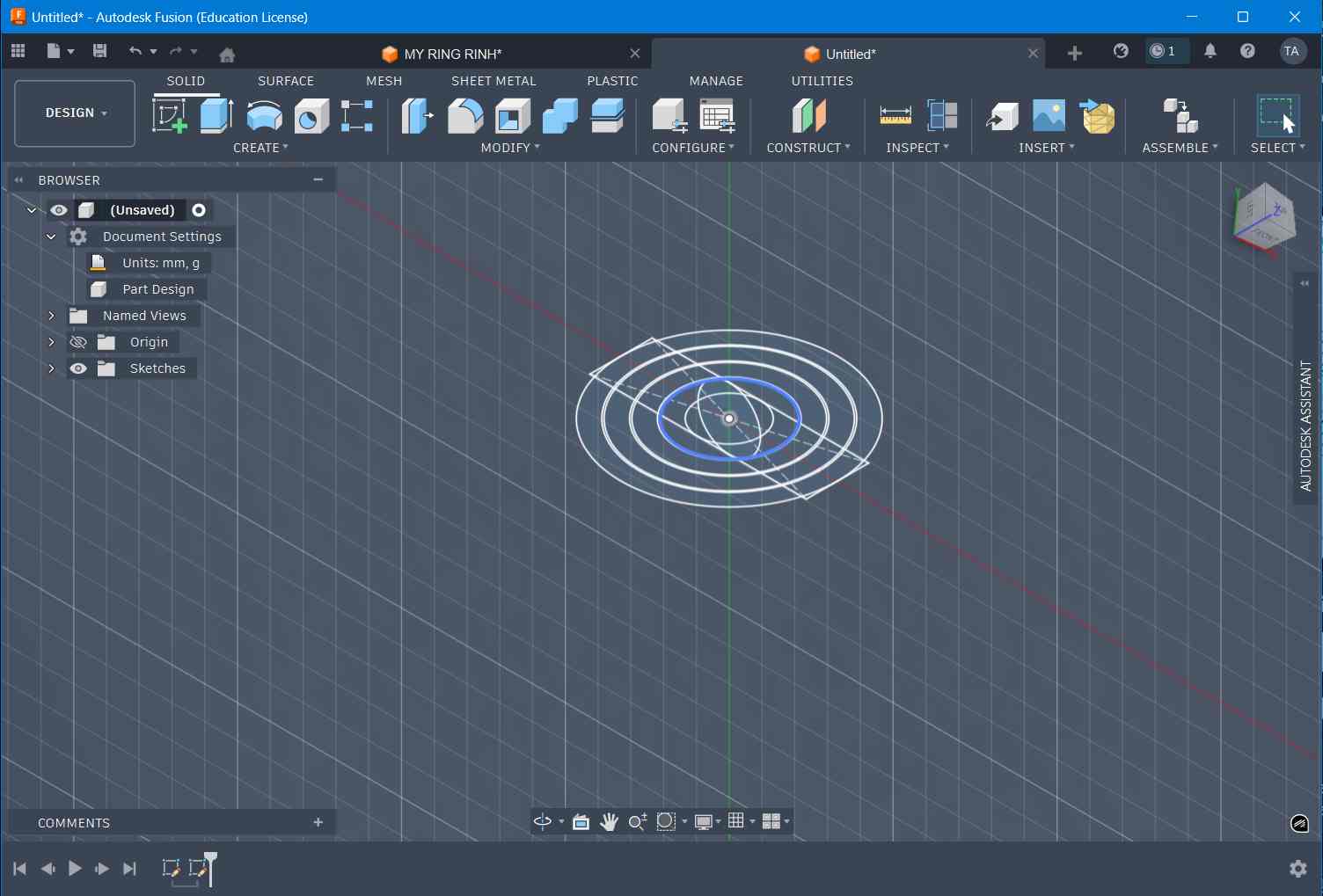
- Switched from isometric view to top view to draw another rectangle and circle structure.
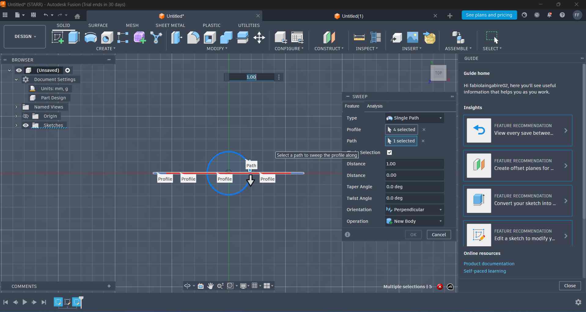
- Created the profile by selecting the circle parts within the created rectangle, establishing the path to complete the section and sketch.
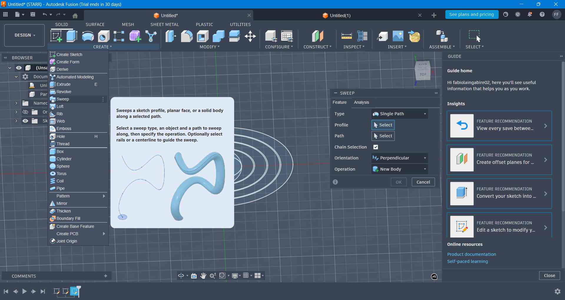
- Utilized the Sweep feature to build the 3D geometry from the profile and path.
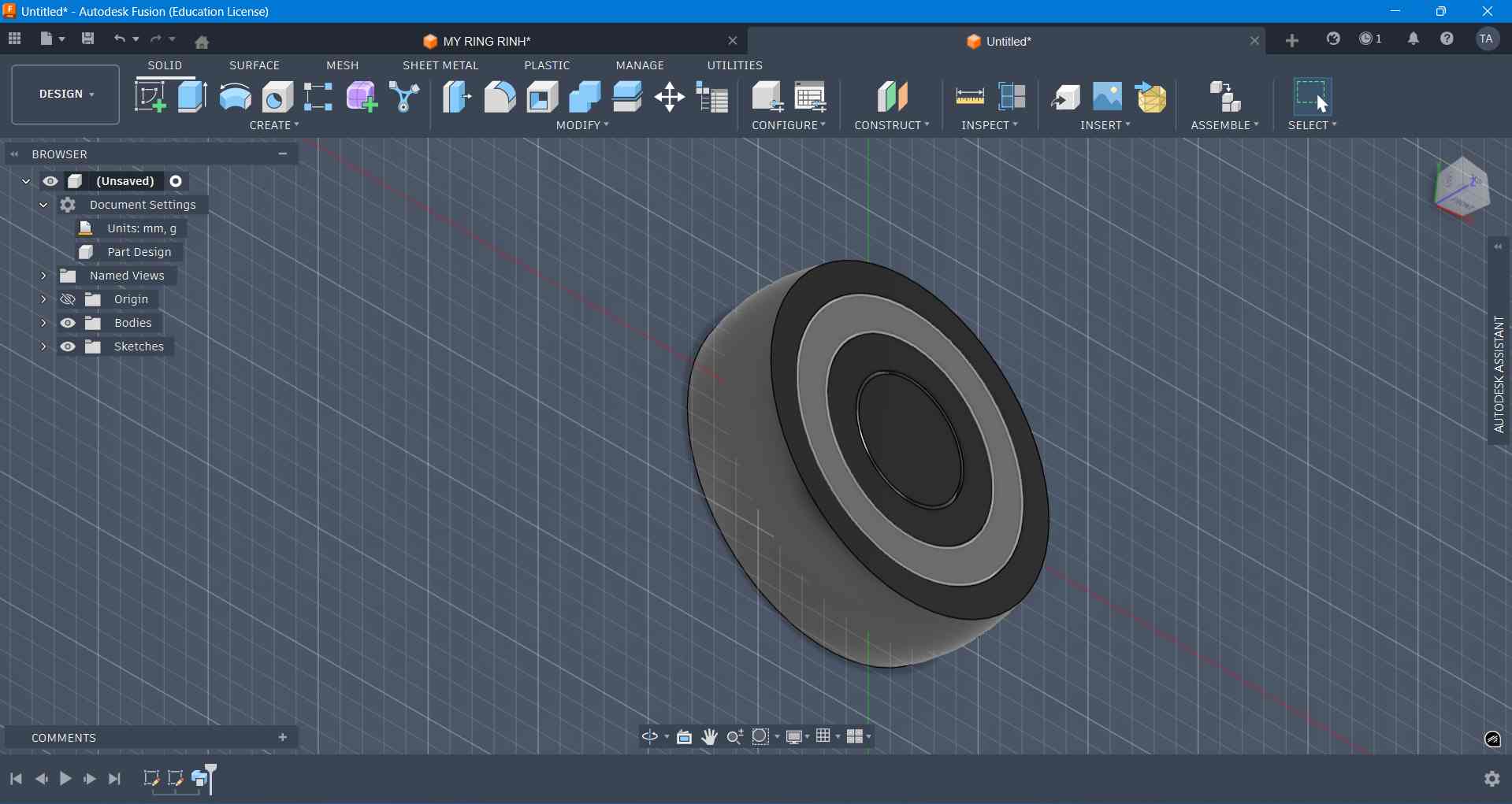
- Here is the final completed design ready for 3D printing:

Export the Design File
I exported my design files into various functional formats, including .dxf, .dwg, and .stl.
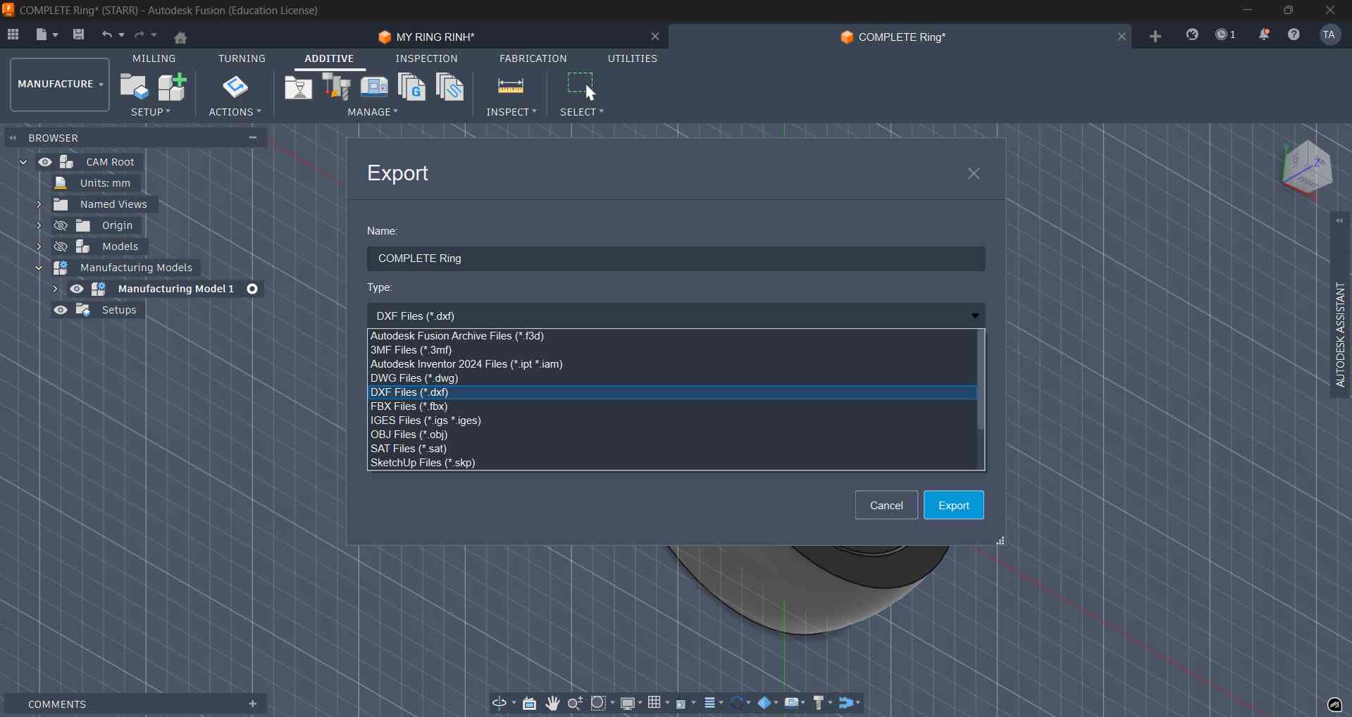
Here the file was ready but the problem I have lost The pc and lost the file two and the new PC Had solidwoks installed In it so I decidedded to choice other deign and use solidworks this helped me to get to know how different software works and how 3d printer and slicer handle all those files
These features are difficult to achieve using subtractive machinery (such as CNC milling) because cutting tools cannot reach inside enclosed internal areas.
Second Trial: Interactive Ribbon Sphere Cat Toy
After the first design failed, I took a different approach using SolidWorks to create a hollow ribbon sphere featuring an enclosed inner ball.
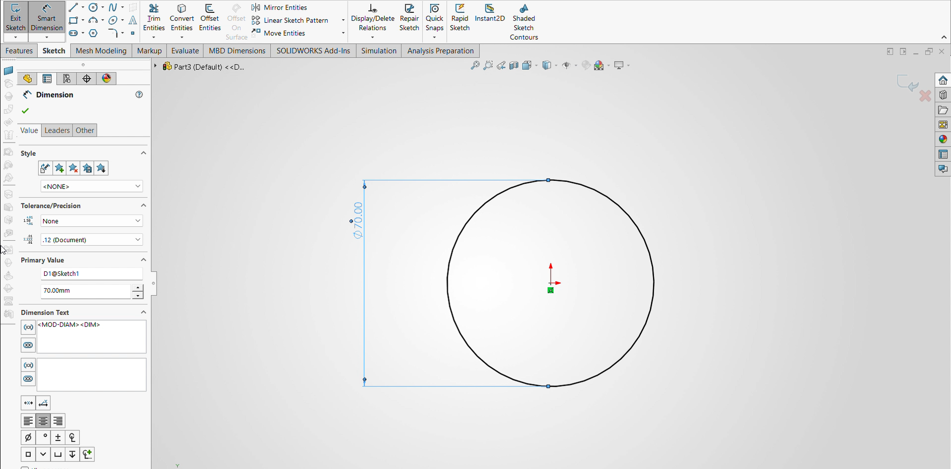
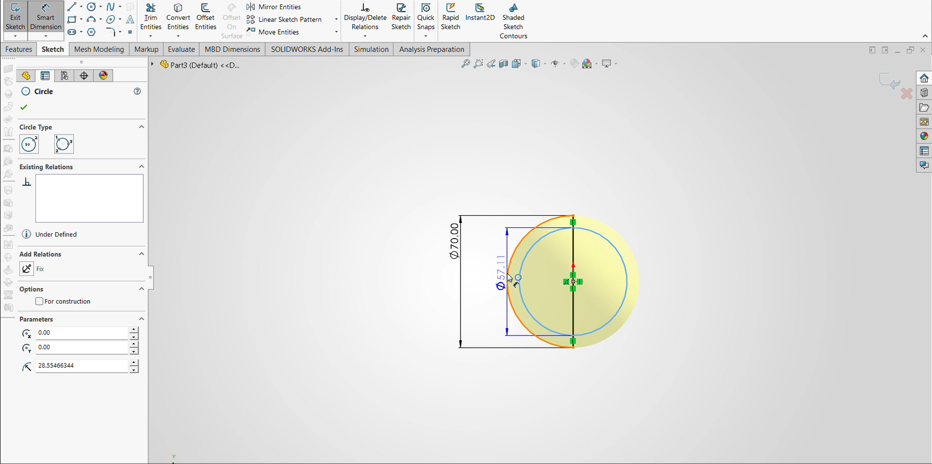
Base Profile Sketch: Sketched a 2D circle of 70mm on the Front Plane to define the outer diameter of the core ball.
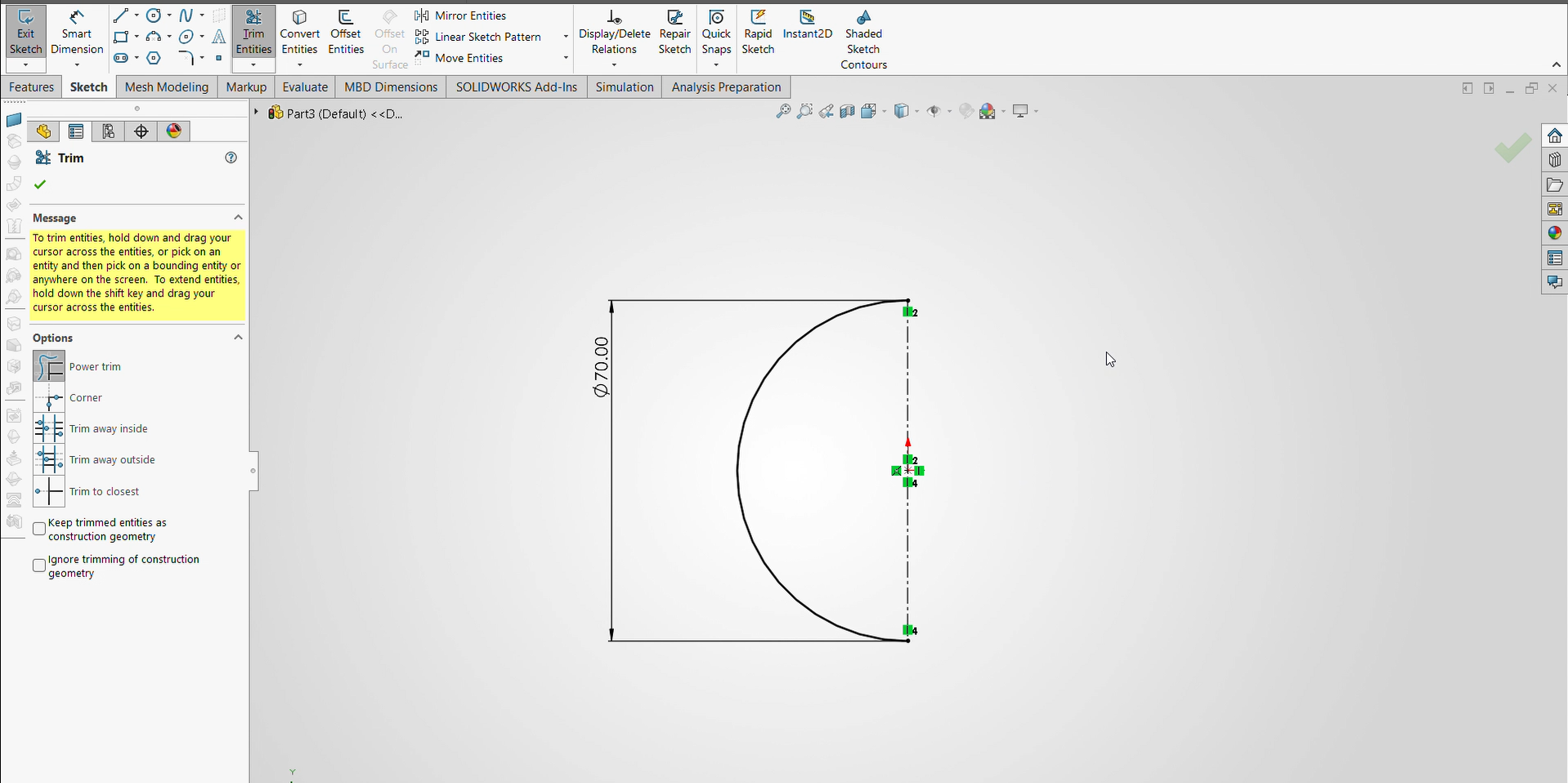
Trimming Half-Profile (Power Trim): Used Trim Entities (Power Trim) to cut the circle along its centerline, leaving a semi-circle profile.
Feature Info: Power Trim removes unwanted overlapping sketch geometry. Used here to prepare a closed 2D profile for a 360° rotational feature.
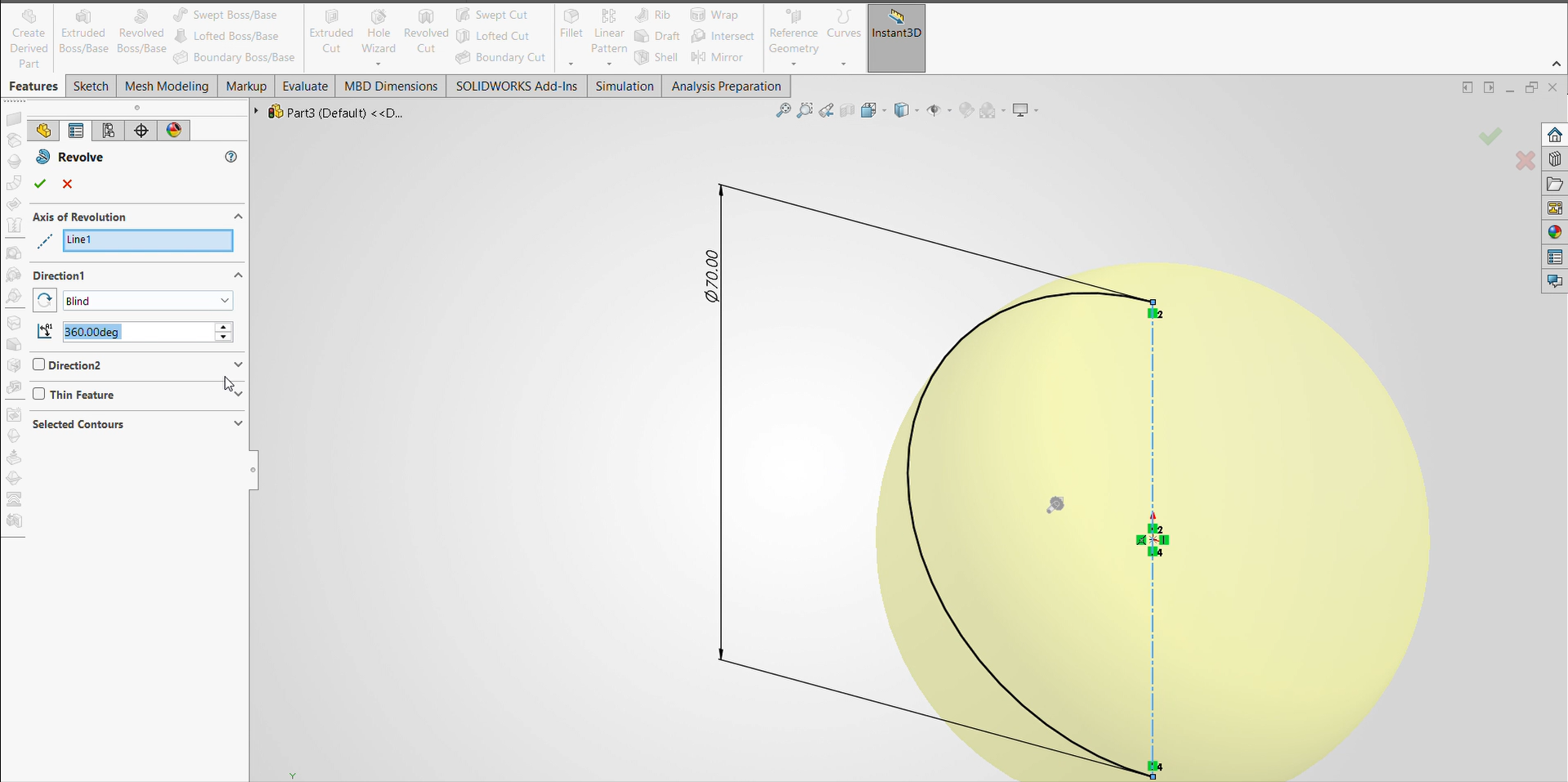
Setting Up Revolve Boss/Base: Selected the vertical axis as the center of rotation to convert the semi-circle into a full 3D sphere.
Completed Core Sphere: The Revolve Boss/Base tool completed the continuous solid sphere.
Feature Info: Revolve turns a 2D profile around an axis. Used to generate cylindrical, spherical, or symmetrical 3D solids.
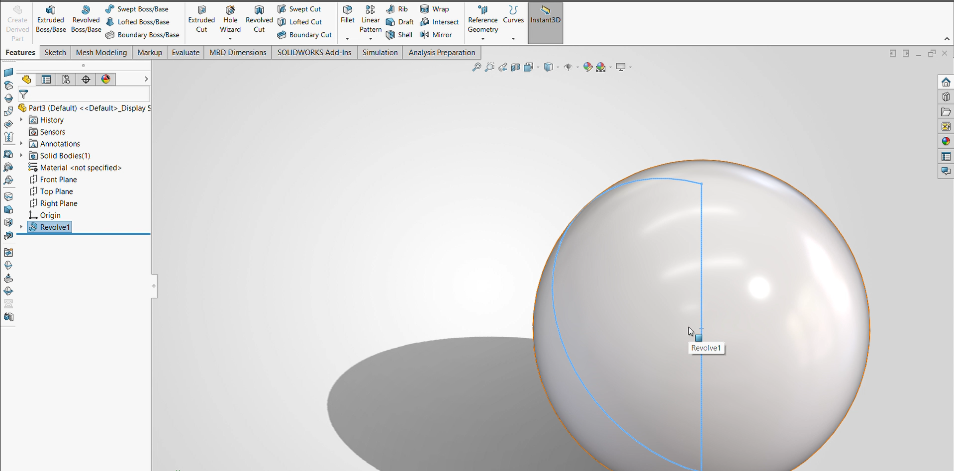
Sketching Rib Cutout Geometry: Created a triangular wedge sketch on the surface plane using construction centerlines and standard sketch lines.
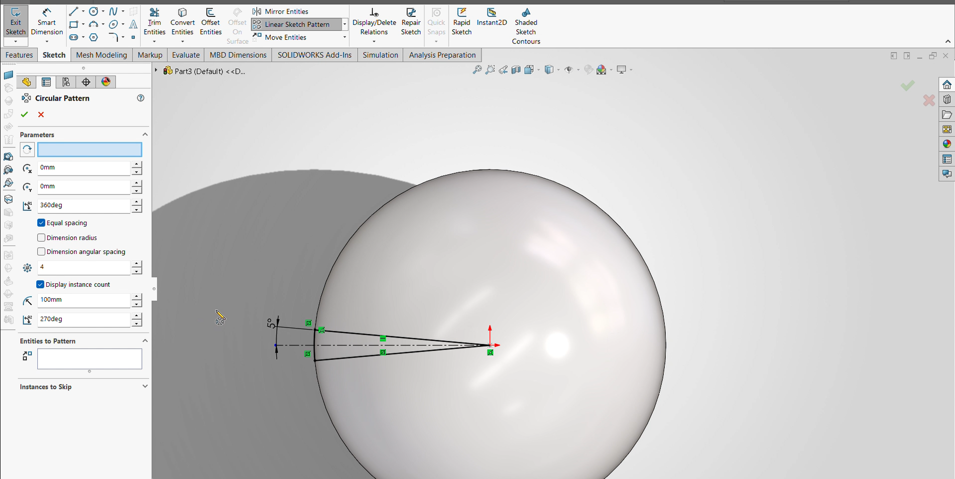
Circular Sketch Pattern: Duplicated the single triangle sketch evenly across $360^\circ$ around the central axis.
Feature Info: Circular Pattern repeats sketch elements around a central point. Used to create symmetrical patterns (like spokes, slots, or slatted ribs) without manually drawing each shape.
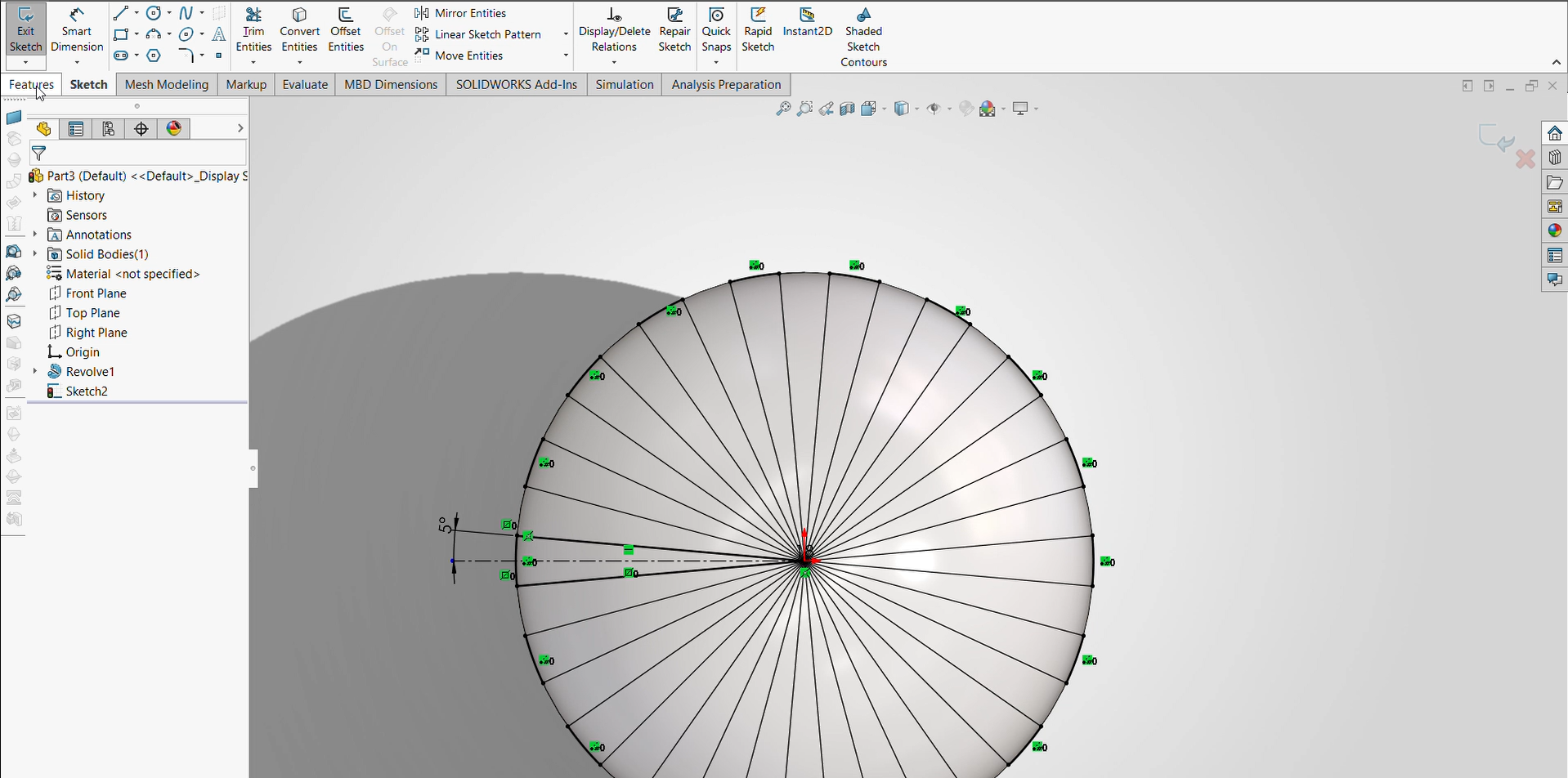 >
>Executing Extruded Cut: Selected the patterned triangular regions and applied an Extruded Cut through the sphere.
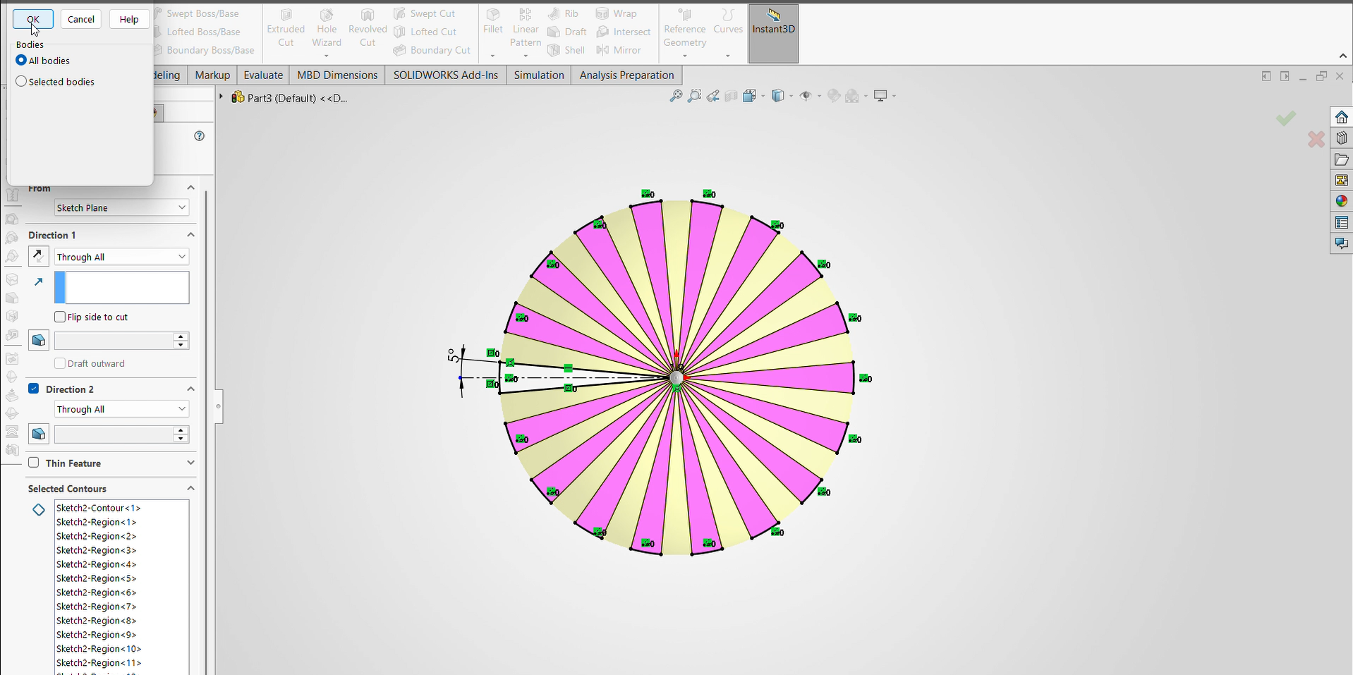
Slatted Outer Shell: The extruded cut removed material from the solid body, creating the open slotted outer cage.
Feature Info: Extruded Cut subtracts material from a 3D model using a 2D profile. Used to form holes, channels, or hollow cage structures.
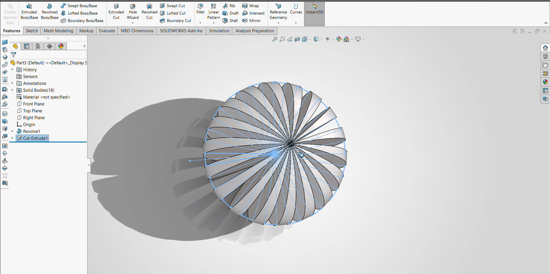
Refining Edge Geometry: Added decorative cuts and angled guide lines to give the ribbon cage a spiraled aesthetic.
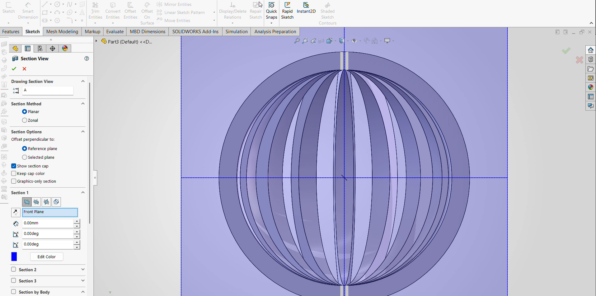
Section View Activation: Enabled Section View to visually cut open the model without altering geometry.
Feature Info: Section View cuts the display model along chosen planes. Used to inspect internal spaces, verify wall clearances, and sketch inside hidden geometry.
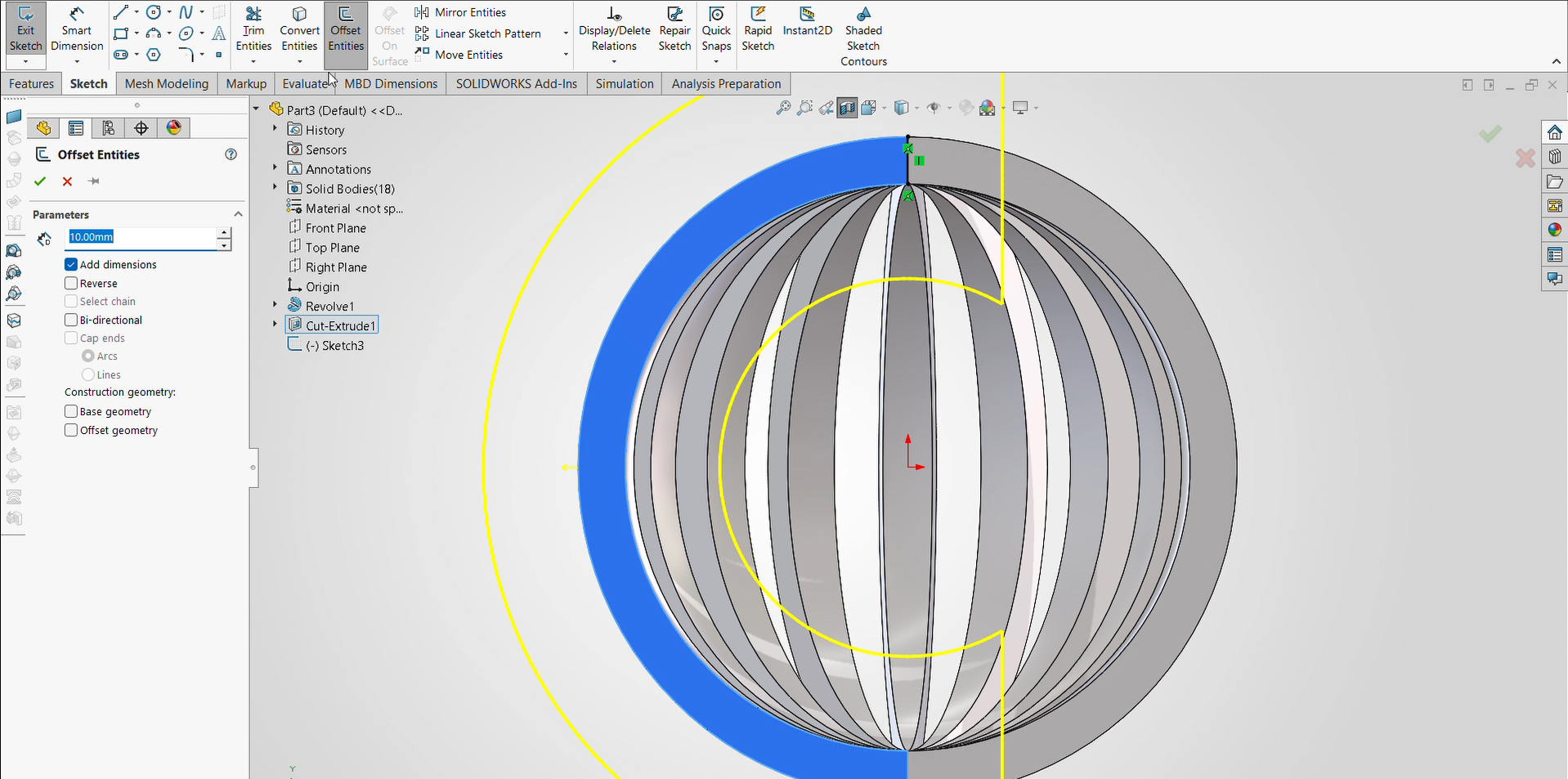
Internal Wall & Core Sketching (Offset Entities): Used Offset Entities to create uniform internal clearance walls and position the floating inner ball.
Feature Info: Offset Entities duplicates existing edges or sketch lines at a specified uniform distance. Used for shell wall thicknesses, clearances, and concentric features.
The video below demonstrates using Section View to model the internal ball directly within the slatted cage:
Model Verification: Inspected the alignment of the internal sphere to ensure it floats freely within the slatted outer cage without overlapping.
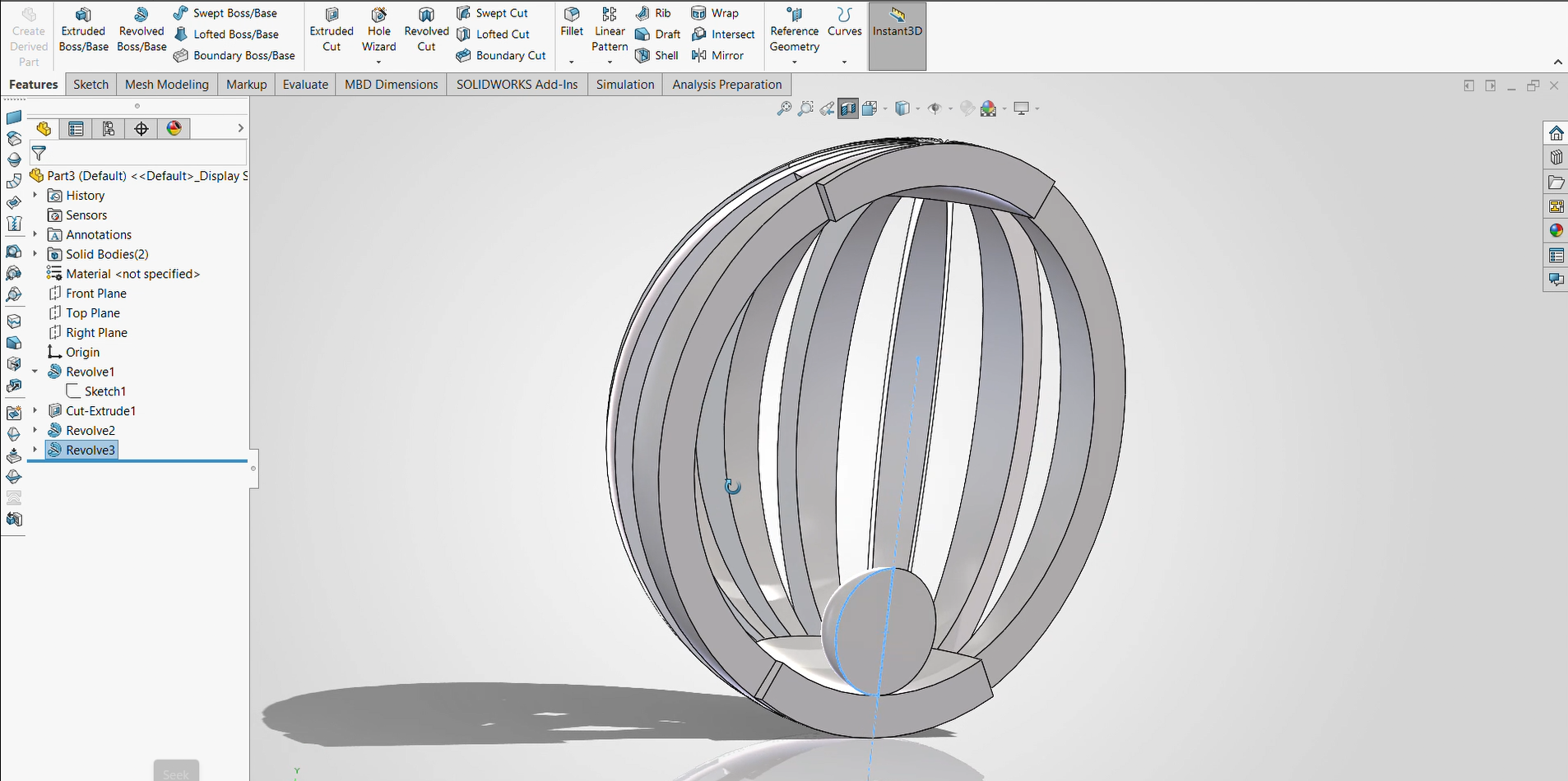
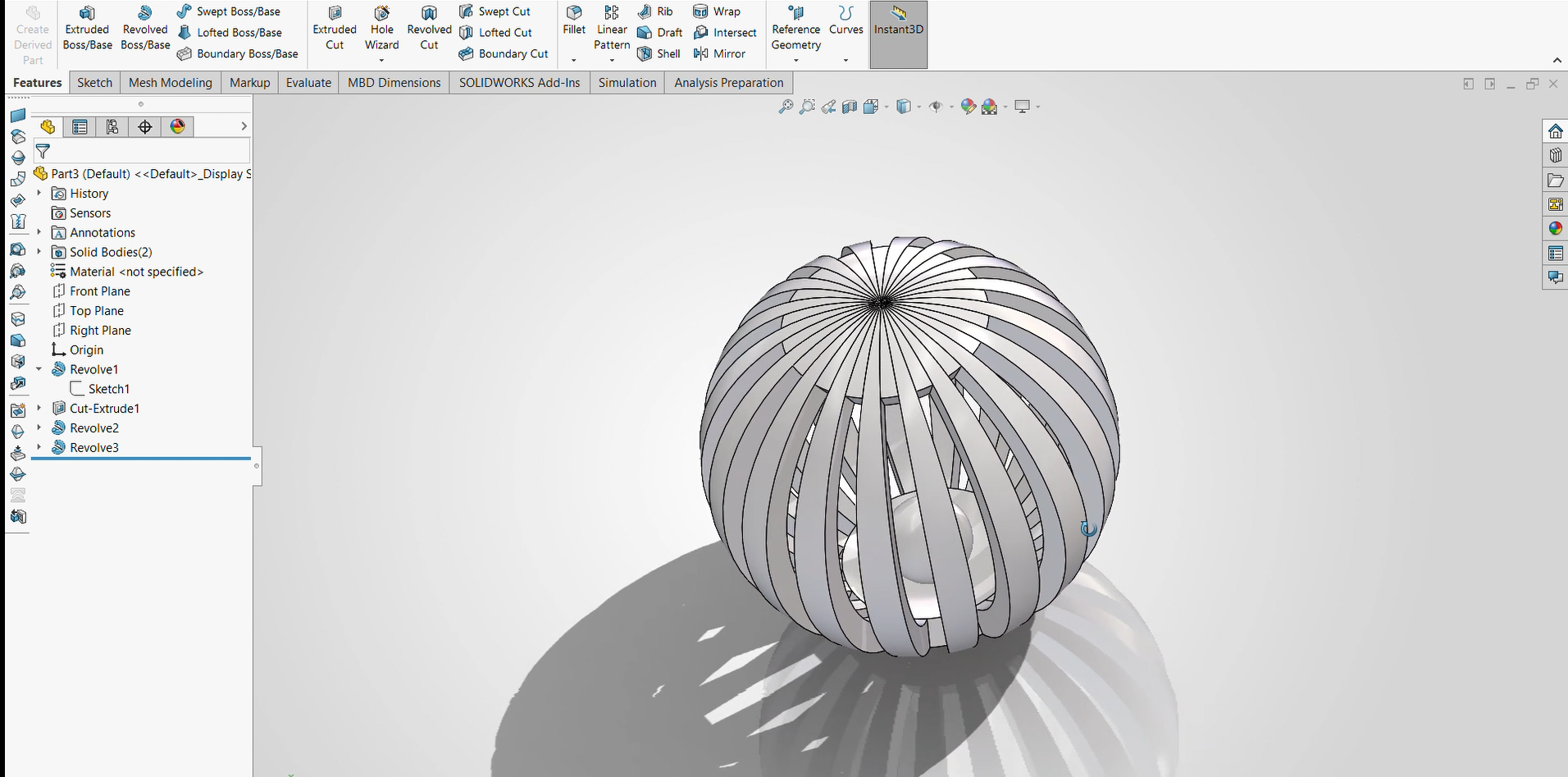
Final 360° inspection video showing the completed print-in-place assembly:
Completed Design Render: Final view of the dual-body cat toy featuring an outer slatted ribbon shell and an enclosed, free-moving inner ball.
3D Printing
I printed the ring using PLA material on our lab FDM 3D printer.
3D Scanning Process: KIRI Engine Initial Attempt
To generate a 3D digital model of a glass water jar with a yellow lid and green straw, I initially chose to test KIRI Engine, a popular mobile photogrammetry application.
Locating the Application: Searched for KIRI Engine: 3D Scanner App on the Google Play Store to initiate the installation process on my mobile device.
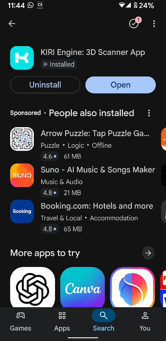
App Installation: Completed the download and opened the application interface to start a new photogrammetry scanning workflow.

Initializing New Scan Project: Accessed the main home dashboard and tapped the "+" (Plus) button at the bottom center to launch the camera capture mode.
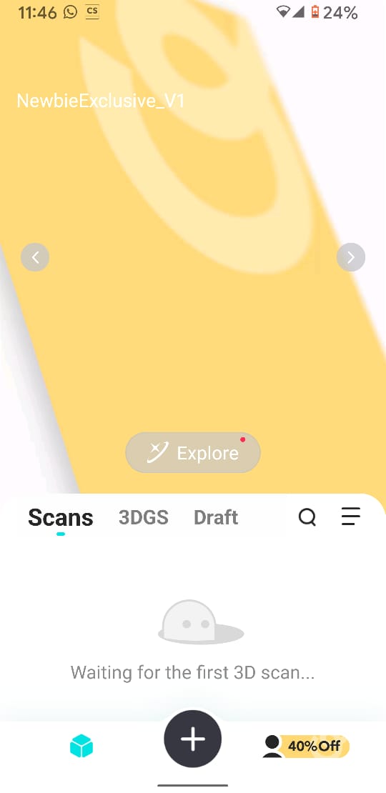
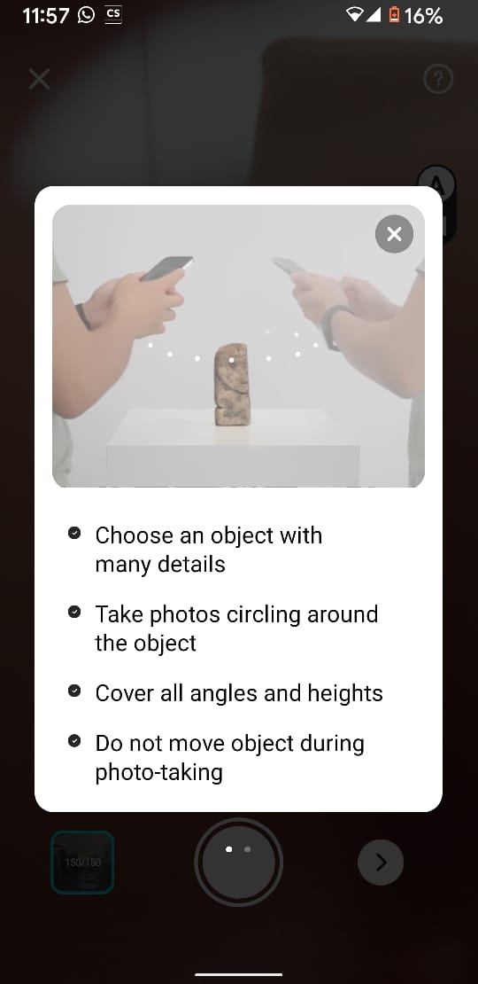
Reviewing Photogrammetry Guidelines: Followed the in-app guidelines for optimal 3D capture:
- Choose an object with detailed surface texture.
- Walk in concentric circular paths around the object.
- Capture photos covering multiple elevations (low, eye-level, high angle).
- Keep the subject strictly stationary during photo capture.
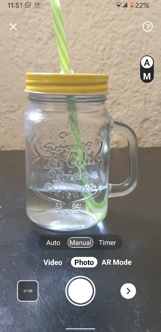
Setup and Initial Capture: Positioned the glass jar on a flat surface and switched to Manual Photo Mode to begin taking overlapping images around the subject.
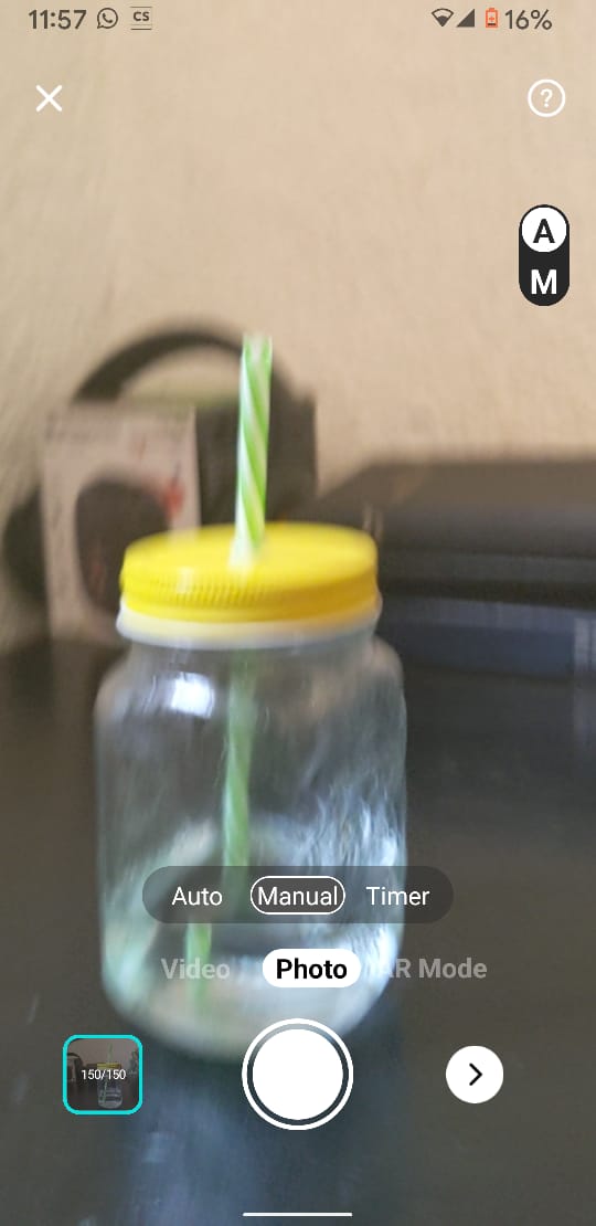
Completing Full Photo Set (150/150): Successfully captured a full 360-degree dataset consisting of 150 detailed photos covering every angle and height of the glass jar.
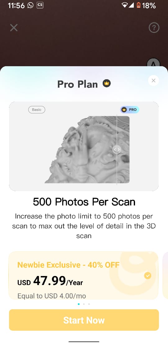
Encountering Pro Plan Paywall Barrier: Upon attempting to process the 150-photo dataset into a 3D mesh, the app prompted a required subscription to the Pro Plan ($47.99/year) to handle high photo limit scans.
Key Challenge & Lessons Learned
1. Paywall Limitation: While advertised as free, processing high-detail image sets (up to 150 photos) requires a paid subscription, making it unviable for free project workflows.
2. Material Challenges with Photogrammetry: Transparent materials like glass, water, and reflective surfaces (such as the glass jar body) present inherent challenges for photogrammetry algorithms because light refracts through them, preventing software keypoint matching.
Next Steps: Pivoting to open-source, local desktop photogrammetry software such as Meshroom (AliceVision) or free tiers like Polycam to process image datasets without paywalls.
Challenges & Problem Solving
-
CAD Compatibility & Backup: Always export and back up design files in open/universal formats (
.STL,.STEP) immediately to prevent work loss if hardware or software access changes. - Software Paywall Workarounds: Free mobile photogrammetry apps like KIRI Engine cap photo uploads behind paid subscriptions ($47.99/yr). Pivot to open-source local desktop tools like Meshroom to process high-resolution photo sets without cost.
- Scanning Transparent Objects: Glass and reflective surfaces fail in photogrammetry because light refraction disrupts feature matching. Apply a temporary matte spray or powder to transparent surfaces prior to scanning.
- Print-in-Place Tolerances: Multi-body print-in-place designs risk fusing. Use Section View to verify internal clearances (minimum 0.4–0.5 mm) before sending files to the slicer.
What I Learned
- Additive Geometry Advantage: Additive manufacturing (3D printing) enables complex enclosed shapes—like a floating sphere inside a slatted cage—that cannot be machined using subtractive CNC tools.
- SolidWorks Modeling Techniques: Used Revolve Boss/Base for spherical bodies, Circular Sketch Pattern with Extruded Cut for outer cage slots, and Offset Entities for uniform clearances.
- CAD Section Verification: Utilizing Section View is essential to inspect hidden internal geometries, measure wall thicknesses, and check part separation before printing.
- FDM Printing Constraints: Always design within printer limits—checking overhang angles (under 45° to avoid supports), bridging gaps, wall thickness, and nozzle-width clearances.
- Photogrammetry Workflow: Successful 3D scanning requires stationary subjects, matte surface textures, and overlapping 360° circular photo passes across low, eye-level, and high angles.