// Week 03
Computer-Controlled Cutting
Assignment Objective
Learn how to safely use computer-controlled cutting machines, characterize the laser cutter, fabricate a parametric press-fit construction kit accounting for kerf, and perform vinyl cutting.
Tools & Technologies
Laser Cutter, Vinyl Cutter, Calipers, Plywood (3mm), Paper/Cardstock, SVG Design Files, Parametric Design Software (SolidWorks), Inkscape for preparing SVG files for Vinyl cutter, Fab Lab Safety Equipment
Group Assignment and Safety Reflection
Group Work Link
Our group assignment documentation can be found here: Group Assignment Documentation!
Safety Reflection
Beyond the listed safety rules, I realized that machine safety is not only about following instructions but also understanding why each rule exists. For example, avoiding PVC (Polyvinyl Chloride) is critical because it releases toxic chlorine gas when cut. I also learned that never leaving the laser unattended is essential due to fire risk. This experience changed how I approach fabrication work, making me more aware of material choice, machine behavior, and environmental safety.
- Always wear safety goggles when operating cutting machines.
- Keep hands clear of moving parts and cutting areas.
- Use proper ventilation when cutting materials that emit fumes.
- Do not cut materials that are not approved for the machine (e.g., PVC).
- Ensure the work area is clean and free of flammable materials.
- Never leave the laser cutter unattended while firing (fire hazard).
- Always verify that the air assistant and exhaust ventilation systems are ON.
- Avoid PVC because it releases lethal chlorine gas.
Laser Cutter Characterization
We tested and characterized our laser cutter to understand how material behavior changes with settings. The key parameters measured were kerf, speed, power, focus, and joint fit.
| Parameter | Value | Notes |
|---|---|---|
| Material | 3mm plywood | Standard test material |
| Kerf | 0.15 mm | Measured from test comb |
| Power | 70–80% | Adjusted for clean cut |
| Speed | 15–20 mm/s | Balanced for precision |
| Focus | Manual focus set on surface | Ensures clean beam concentration |
| Cut Type | Vector / Raster | Vector for cutting, raster for engraving |
Individual Assignment - Parametric Press-Fit Kit
For my individual assignment, I designed a 3D waffle structure (vase form) that acts as a parametric construction kit. It consists of intersecting vertical fins and horizontal rings that lock together.
Parametric Design Logic
This construction kit is parametric because key dimensions such as slot width, spacing, and ring diameter control the entire structure. By adjusting these parameters in SolidWorks, the full model updates automatically without rebuilding the design. This allows the kit to adapt to different material thicknesses and fabrication conditions.
CAD Software Used
I used SolidWorks for the 3D modeling of the press-fit kit. Download link: Download SolidWorks
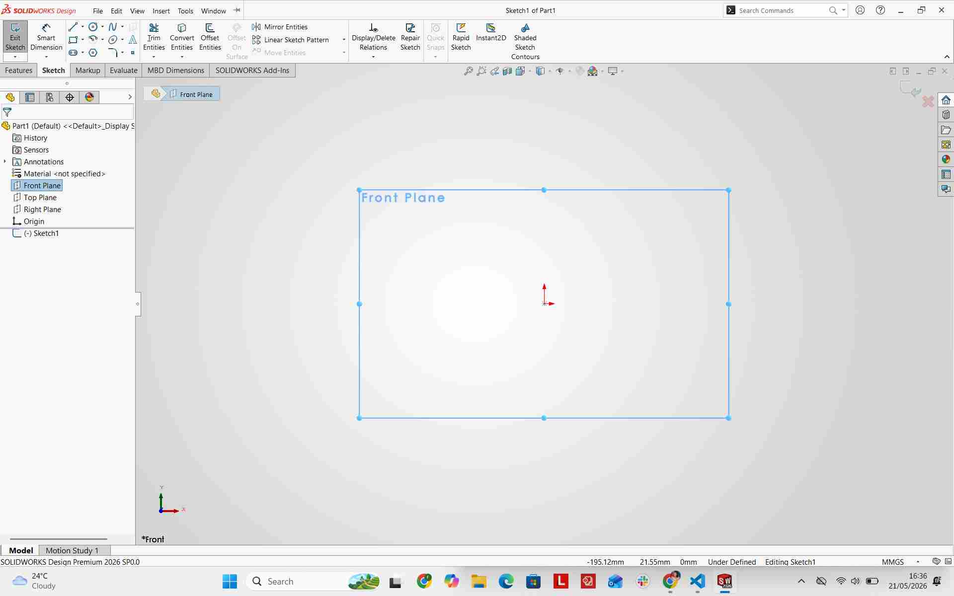
Design Process
In the beginning, I started by selecting the front plane for my base sketch.
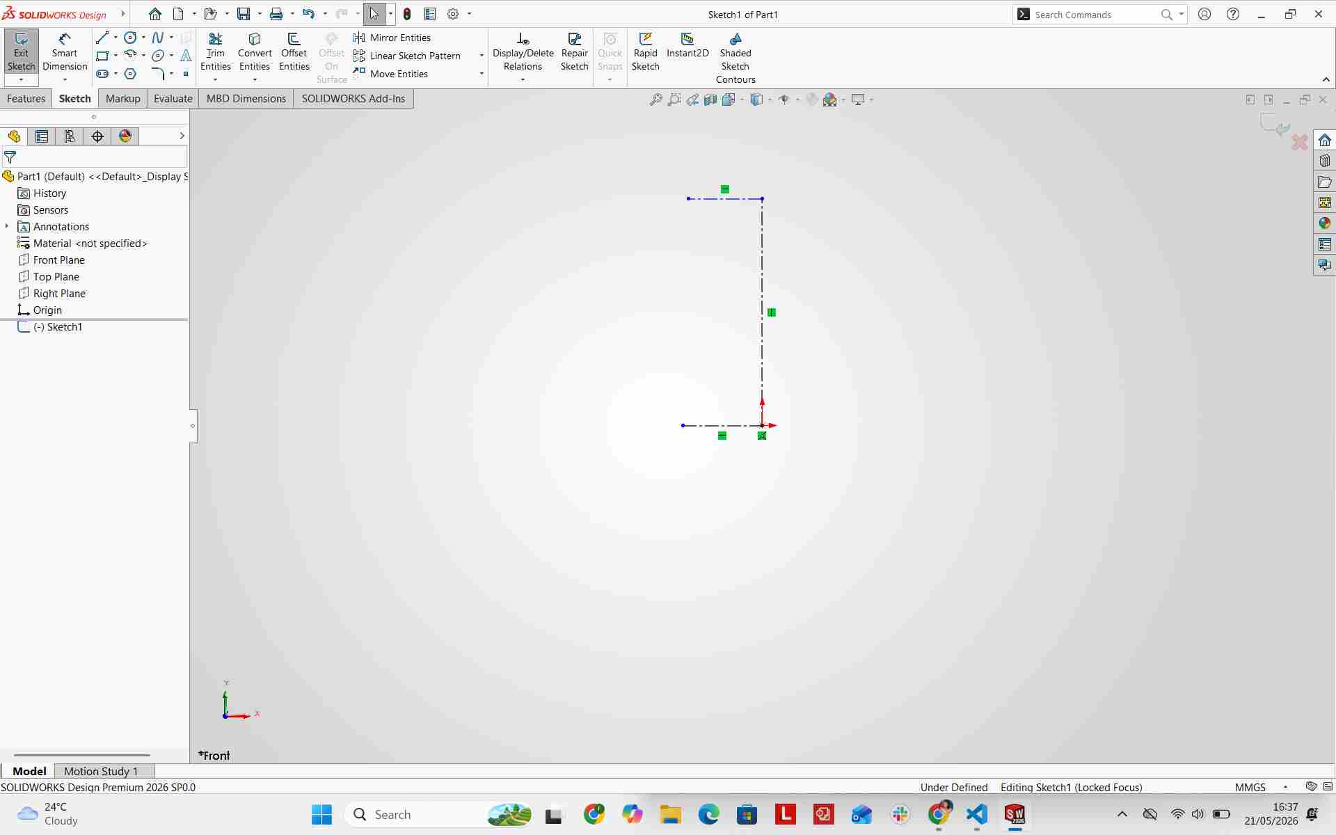
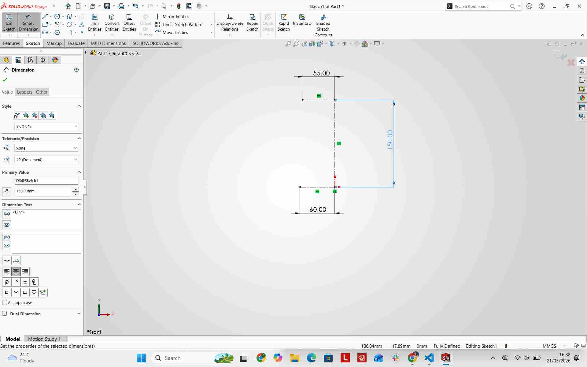
Adding Centre Lines and Dimensions
I added centerline geometry to form the initial framework and applied dimensions to ensure everything was fully constrained.
I began adding the primary base profile lines.
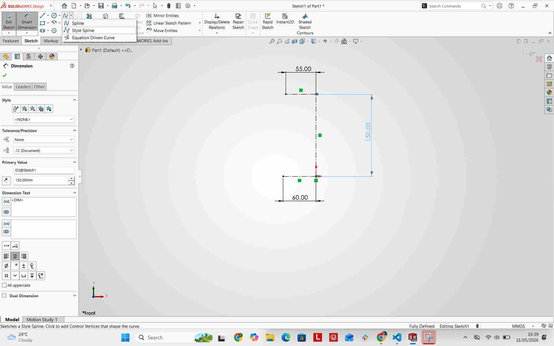
Adding Style Spline
I added a style spline to curve the outer profile and defined its control points with precise dimensions.
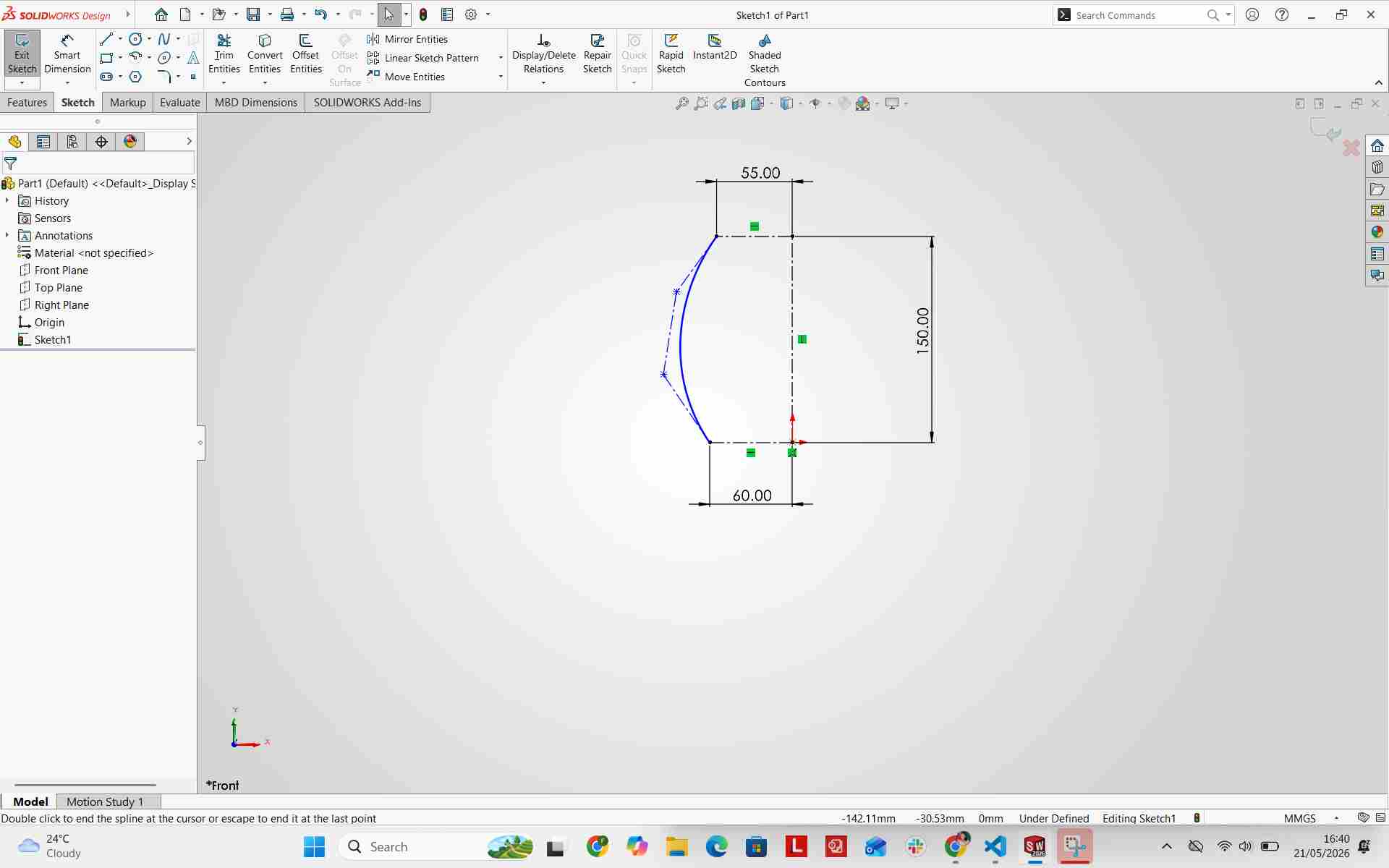
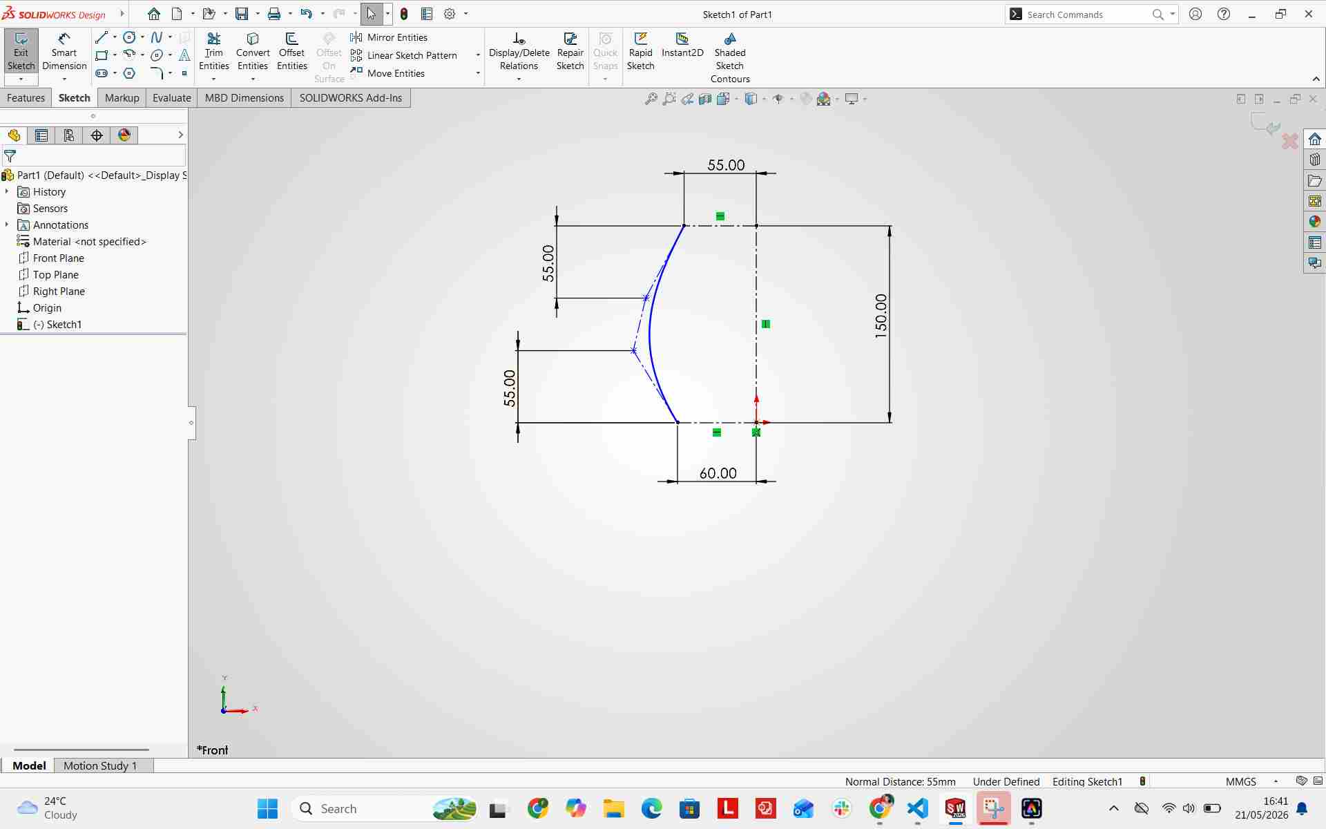
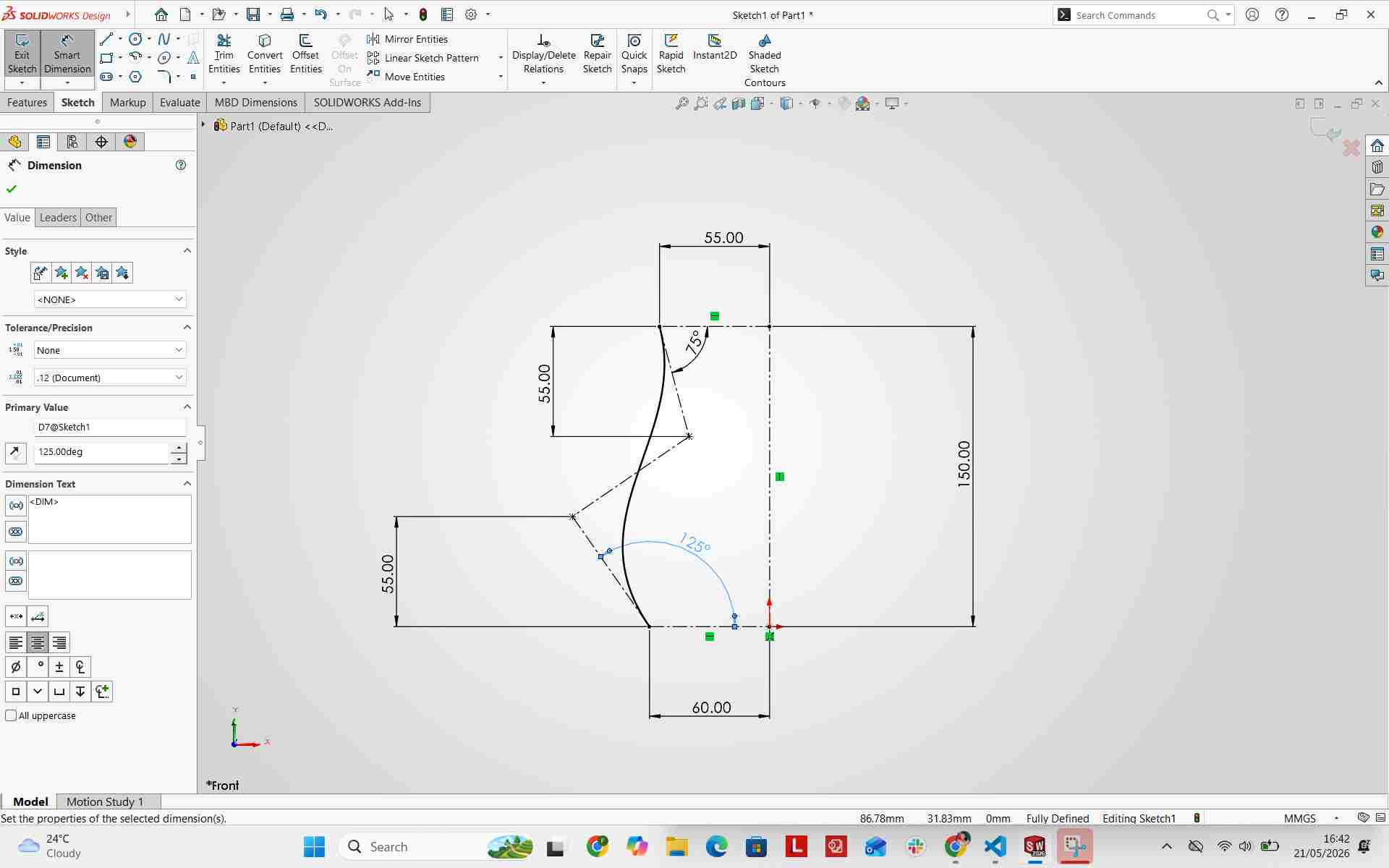
I referenced the style spline and centerlines to set precise corner angles and fully define the geometry.
Adding Joint Rectangles
I created rectangular cutouts that serve as the slots for the press-fit joints.
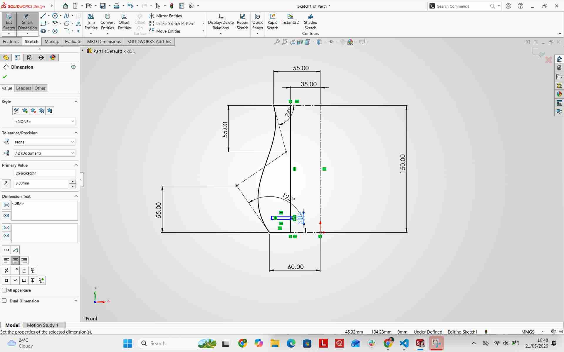
To keep the joint slots aligned along the curved profile, I created a 10mm construction geometry offset line. Each slot was set to a width of 3mm (matching material thickness) while positioned at varying heights along the base.
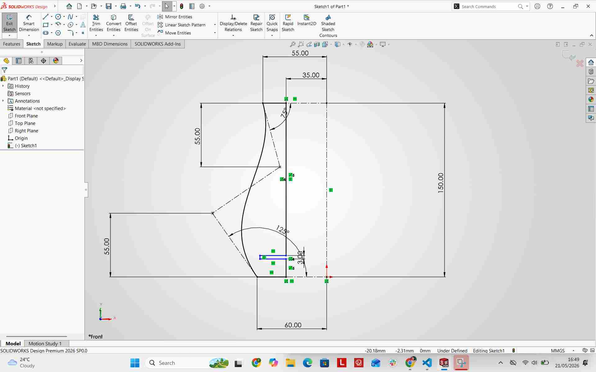
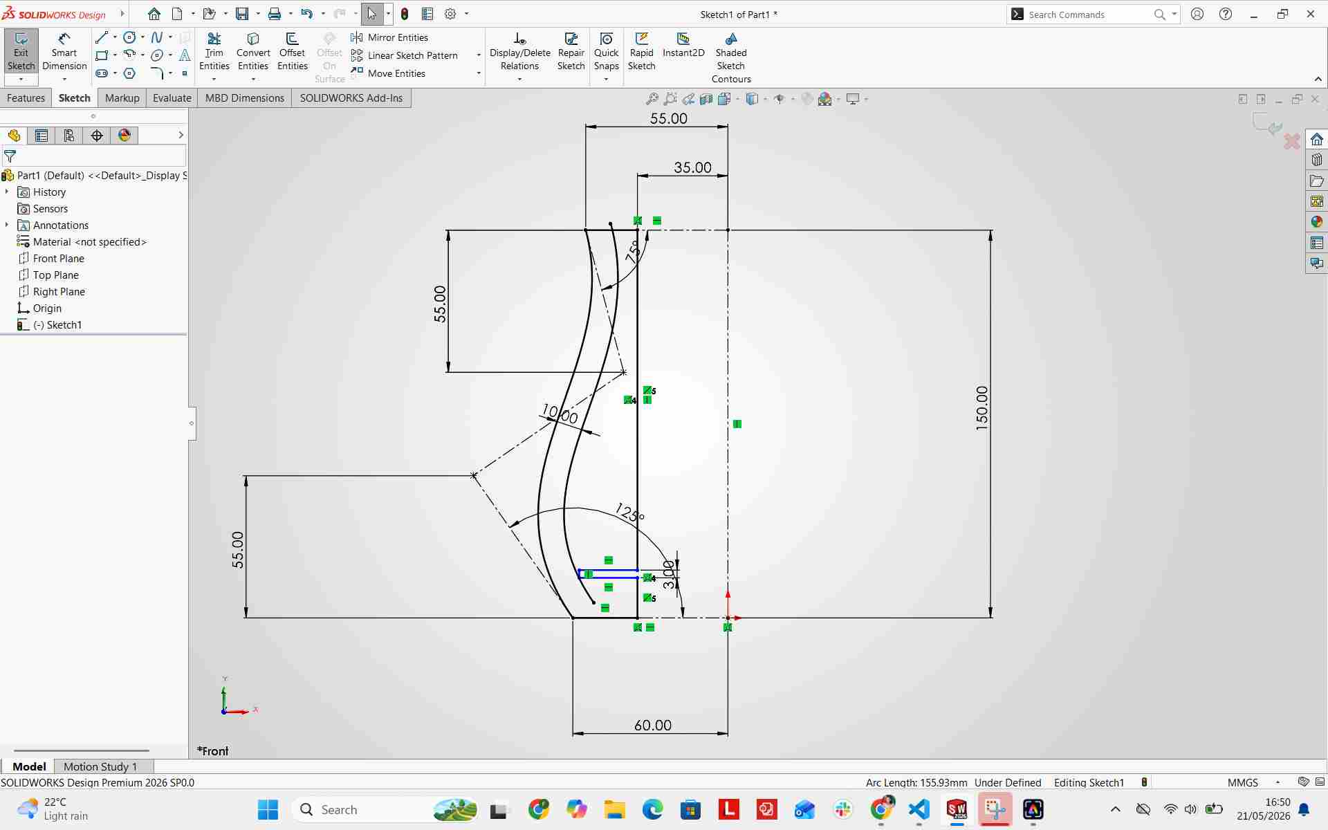
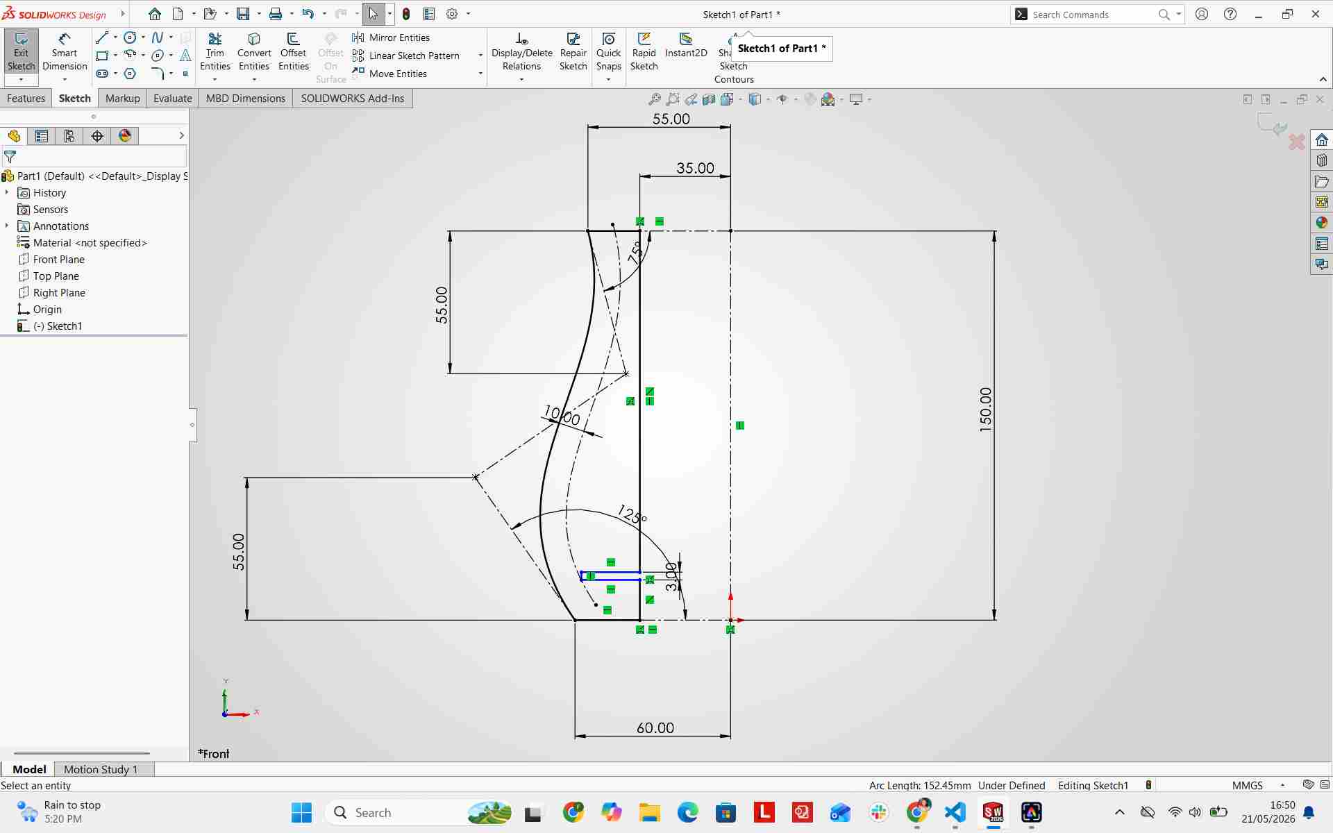
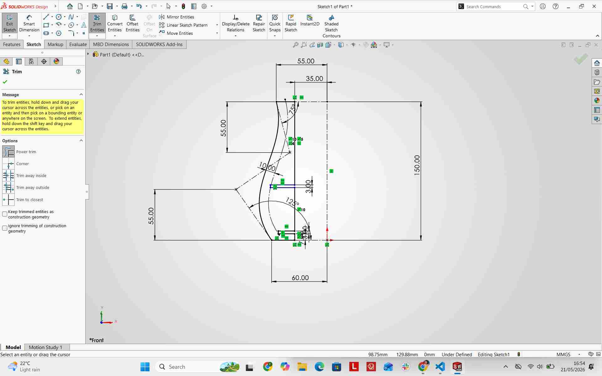
I verified all dimensions to ensure the sketch remained fully defined.
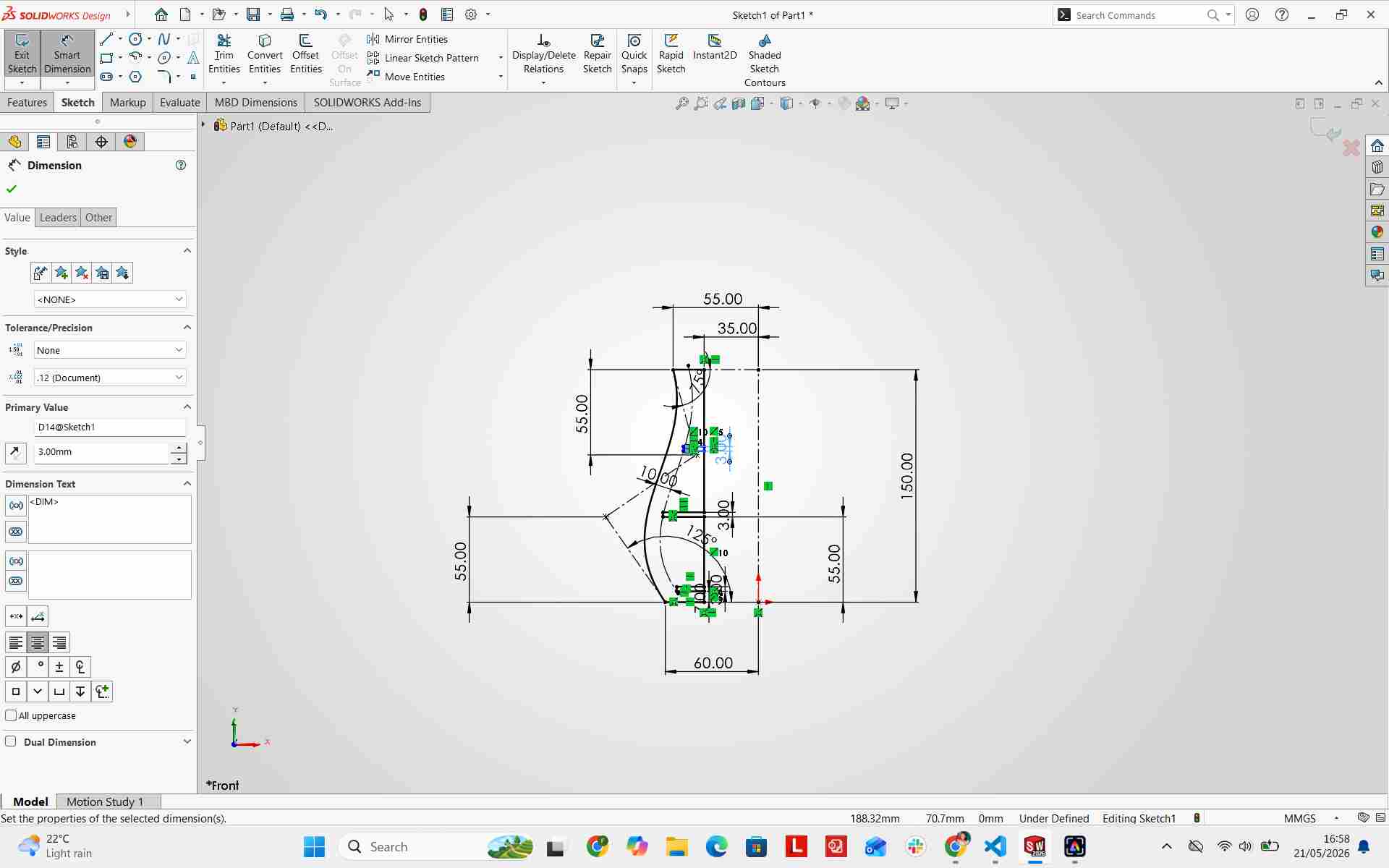
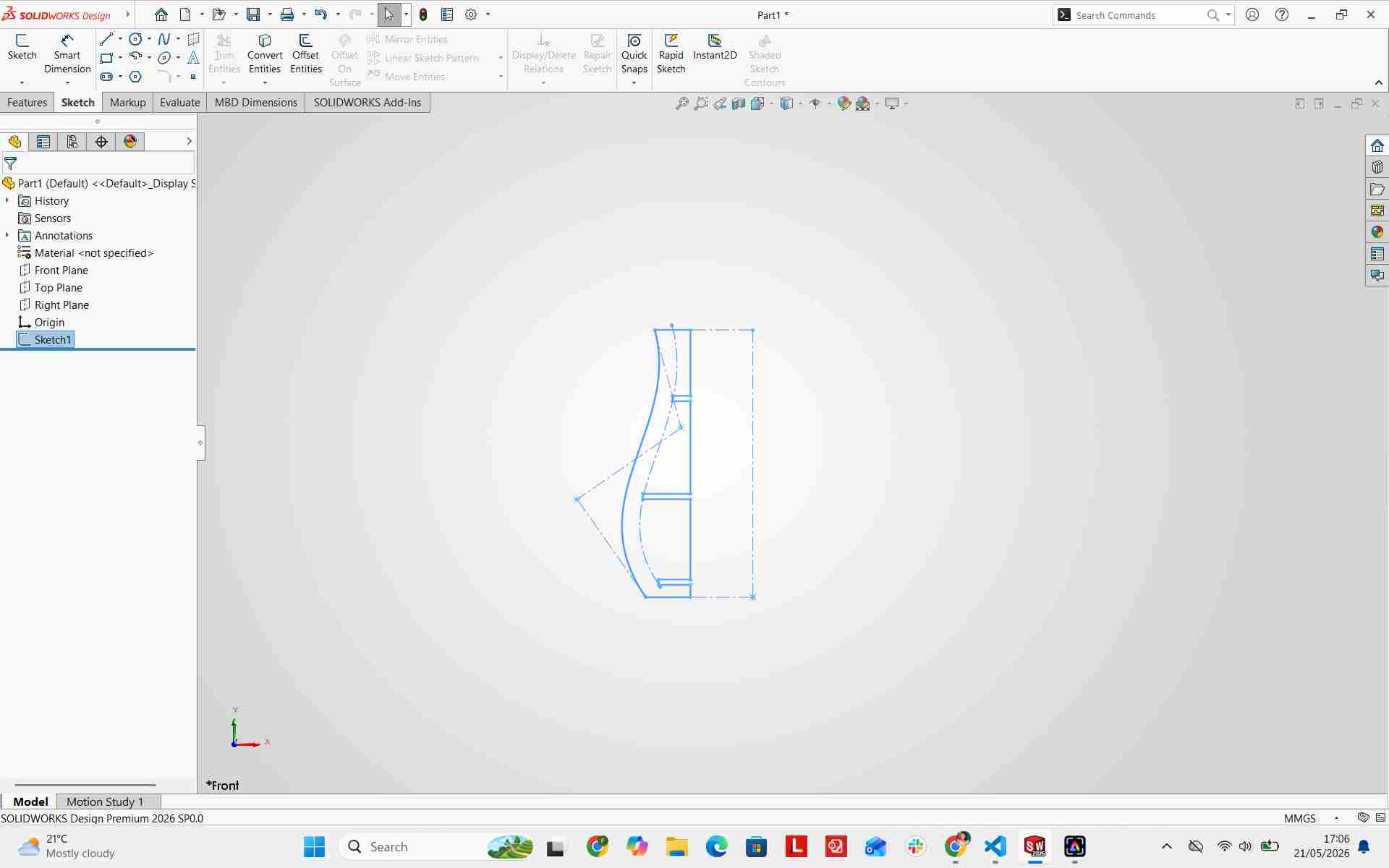
Extruding the Design
I used the Power Trim tool to open the slots, then extruded the profile by 3mm (matching the stock material thickness).
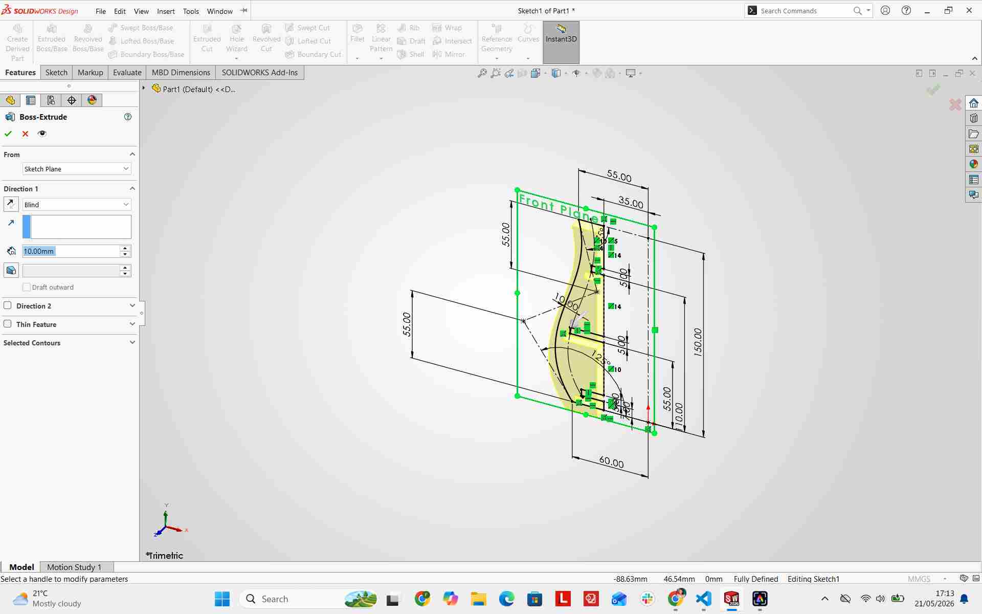
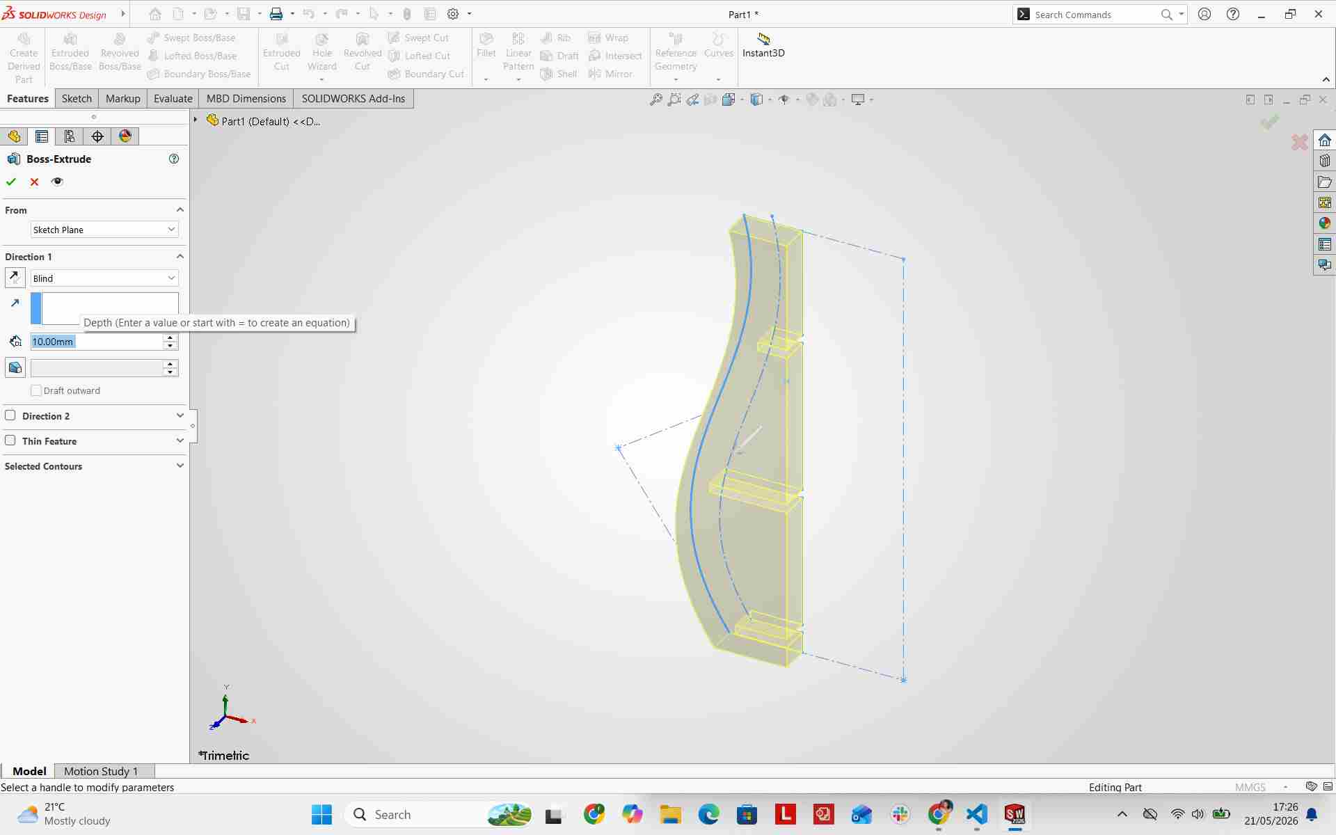
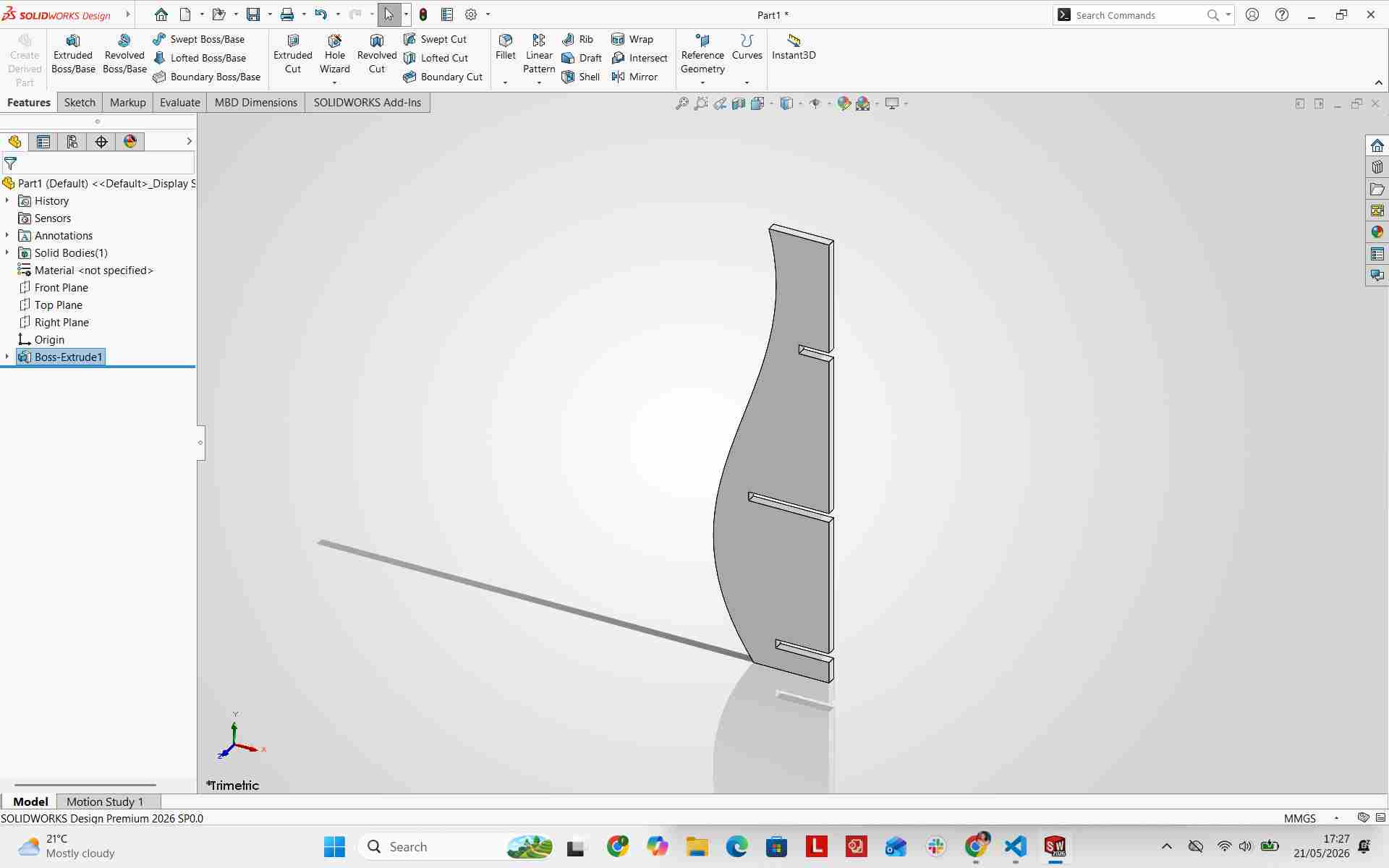
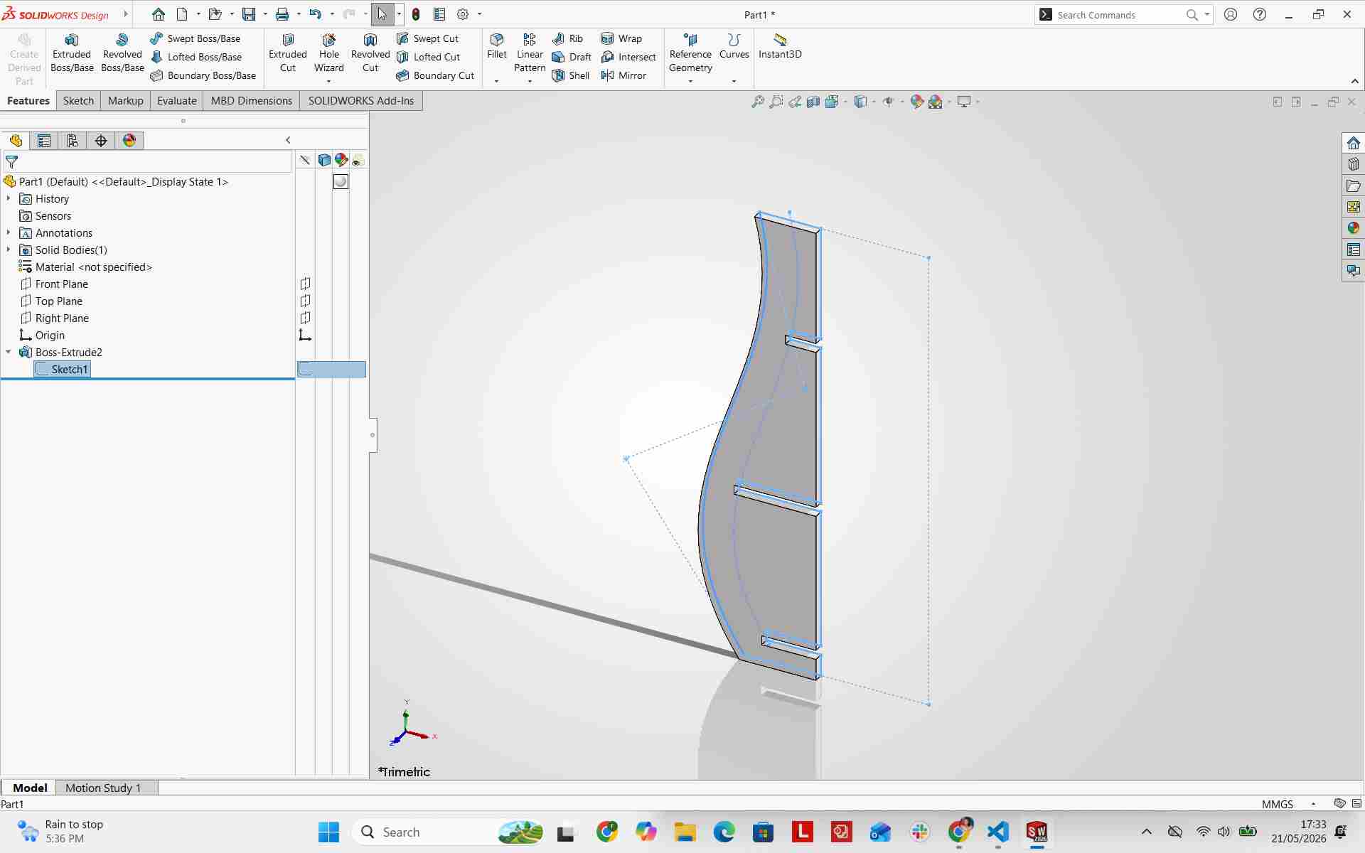
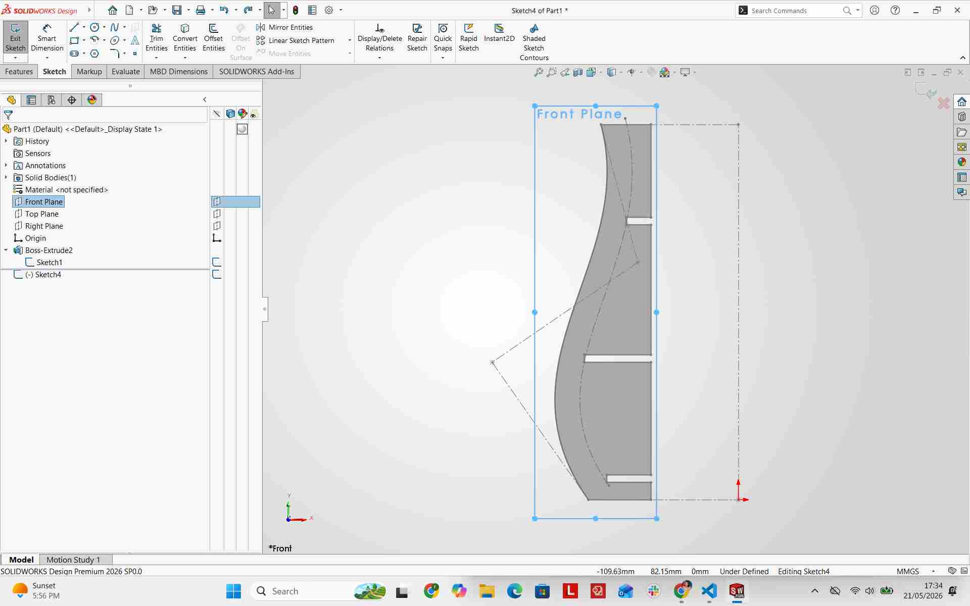
With the primary vertical fin created, I began modeling the interlocking horizontal rings.
Designing the Rings
I sketched a central axis line originating from the front plane origin to guide the revolving features.
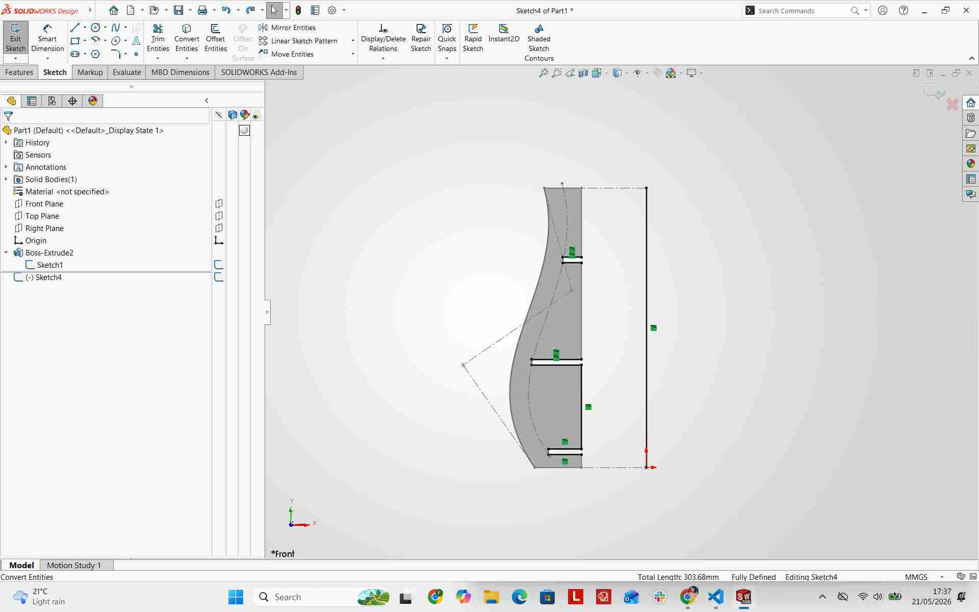
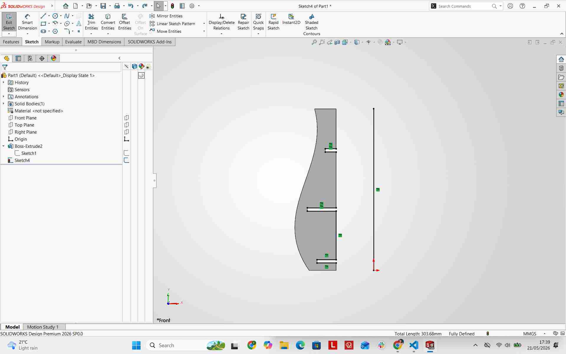
Making Offset for the Rings
I created a 1mm reverse offset for the internal profile of the ring joints and converted the centerline into construction geometry.
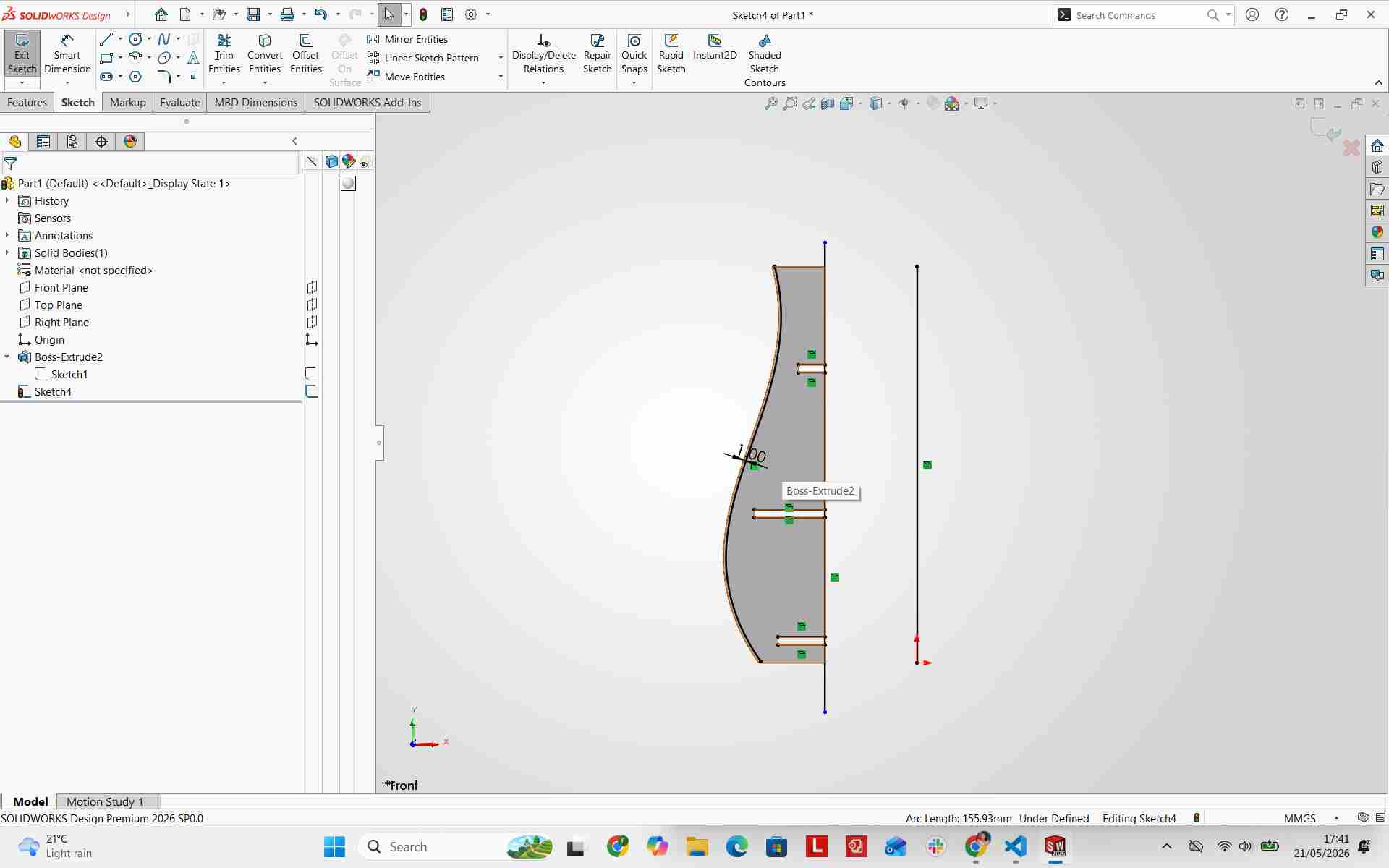
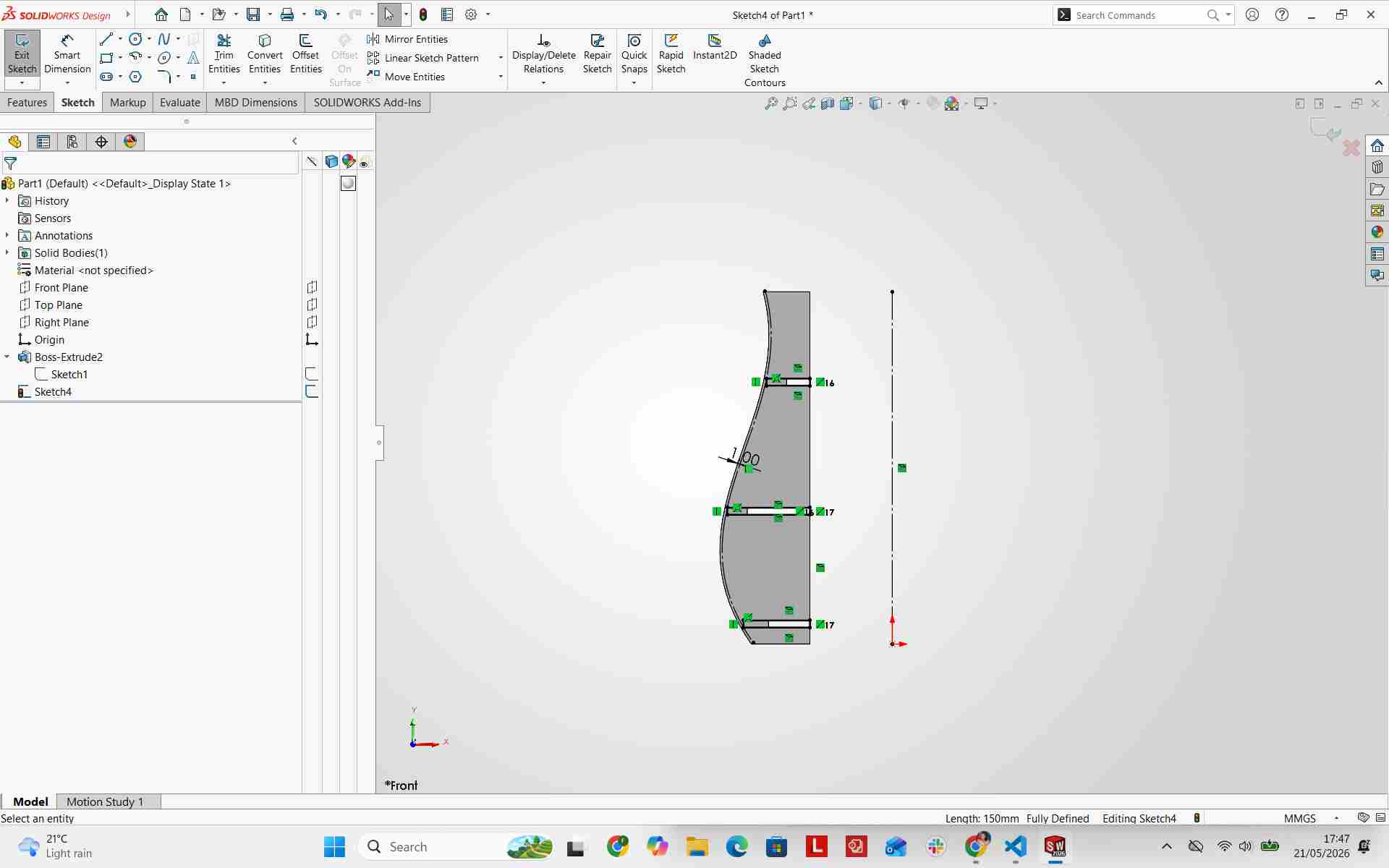
Making the Rings Collinear
Using Power Trim, I extended the rectangle edges to the central axis line to make them collinear, then used Revolve Boss to generate the 3D ring solids.
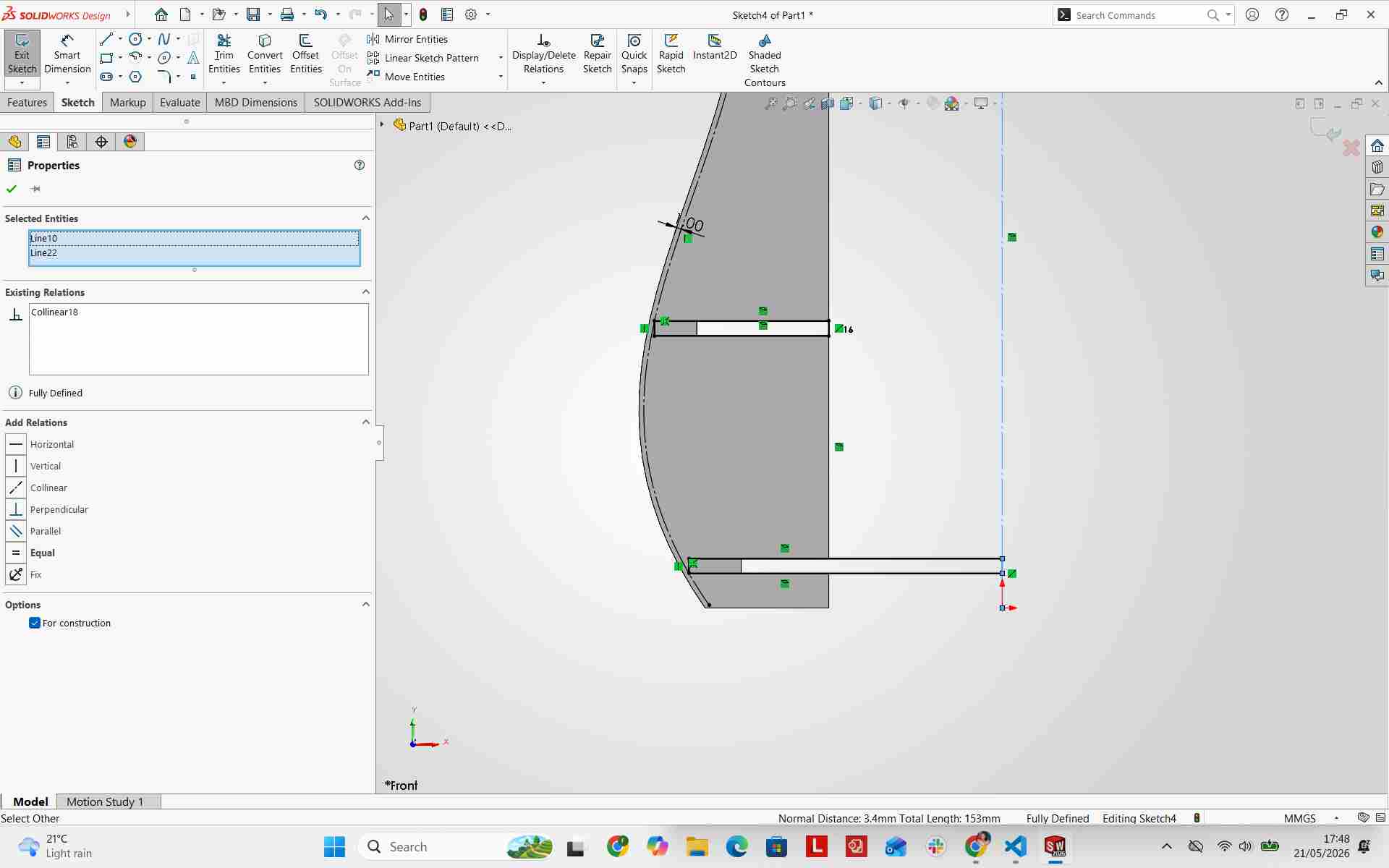
Revolve Boss for the Rings
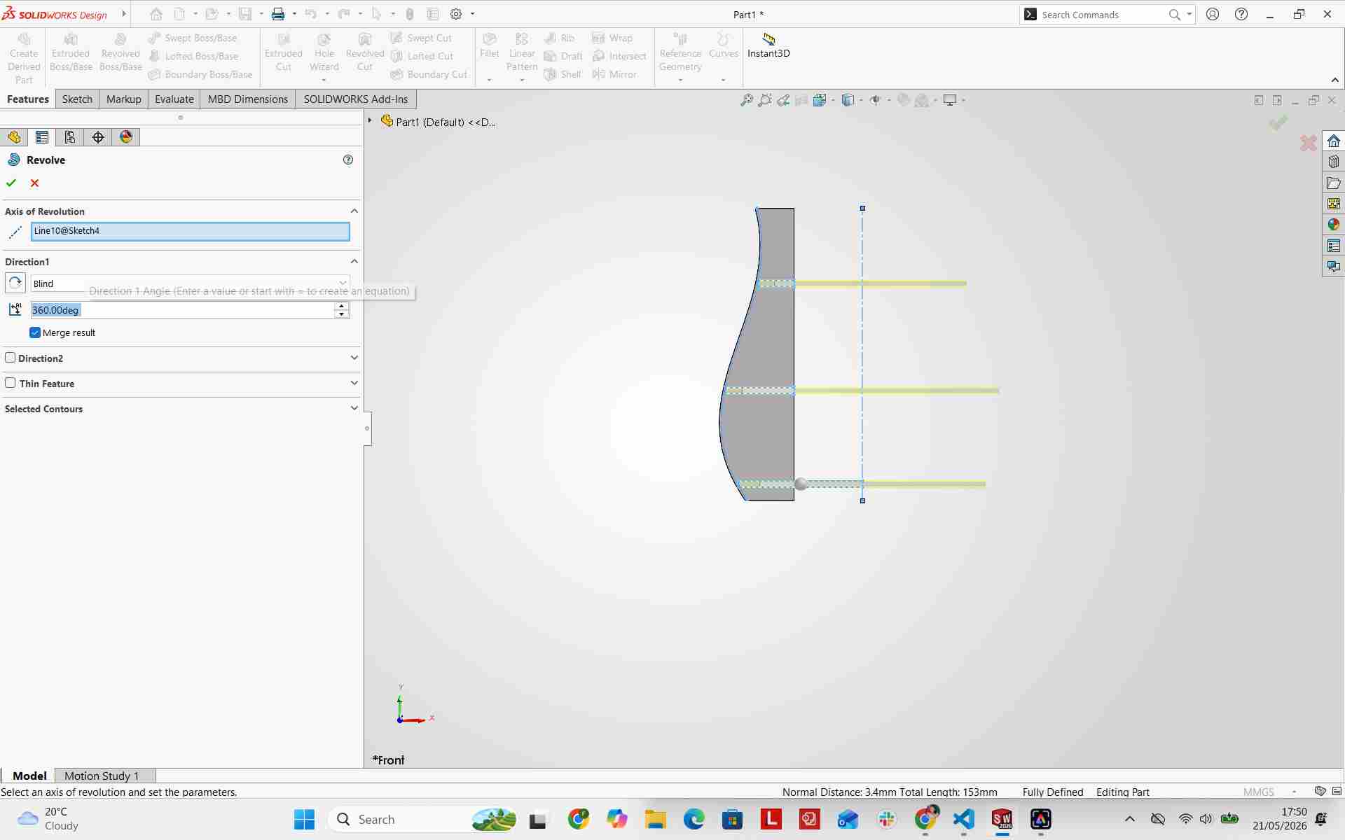
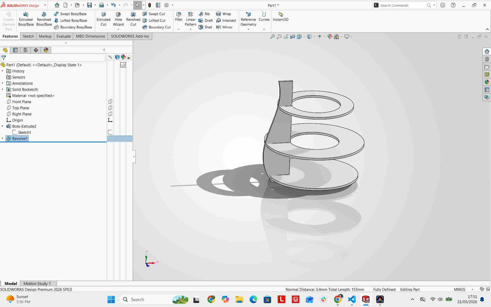
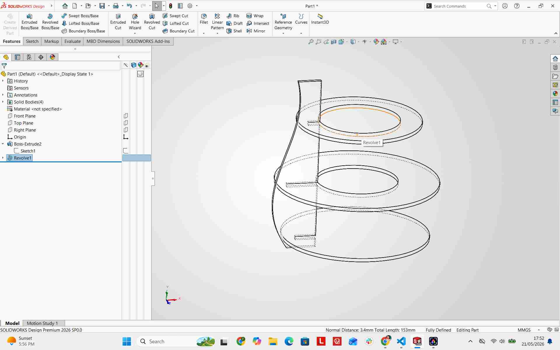
Move/Copy Bodies
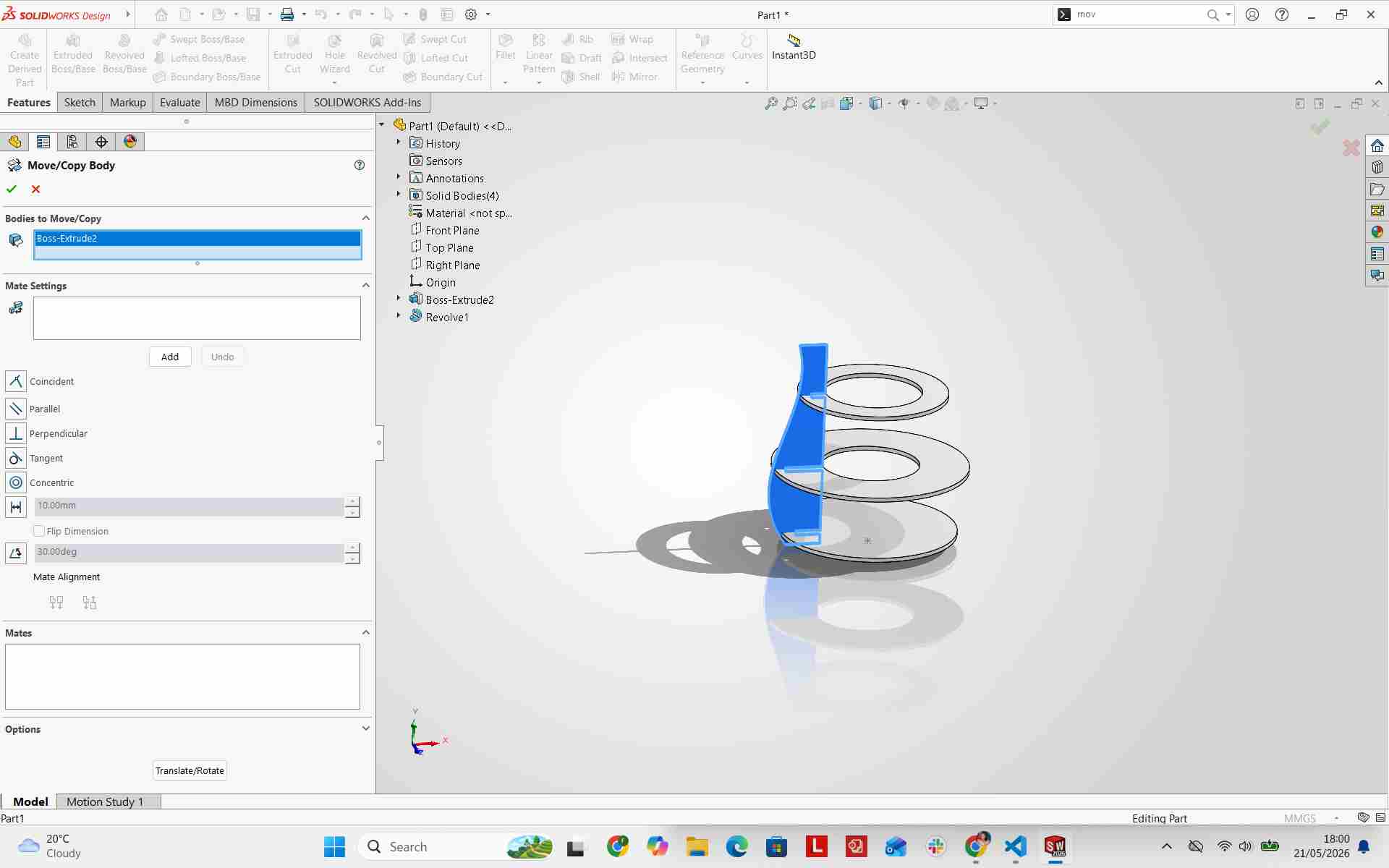
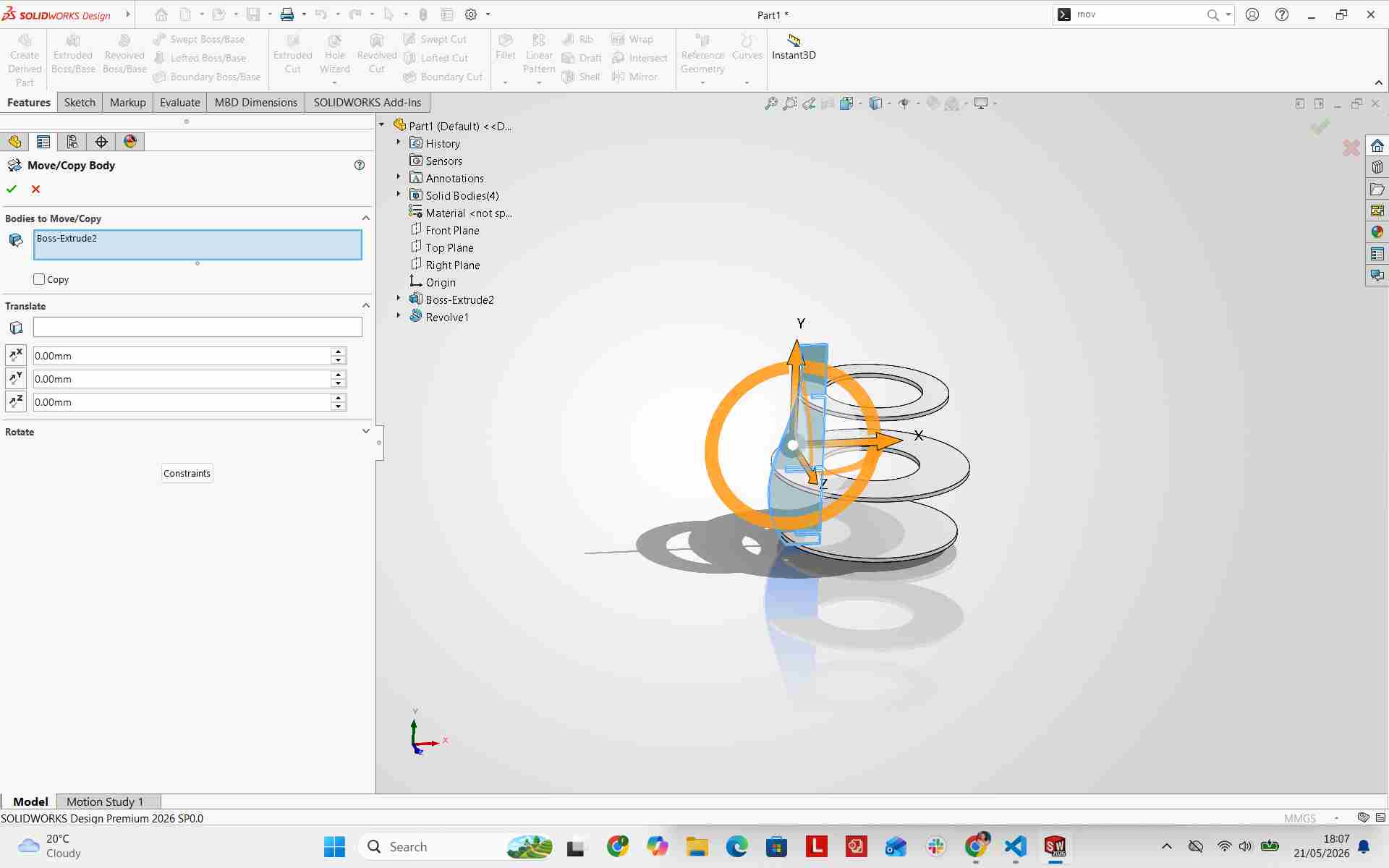
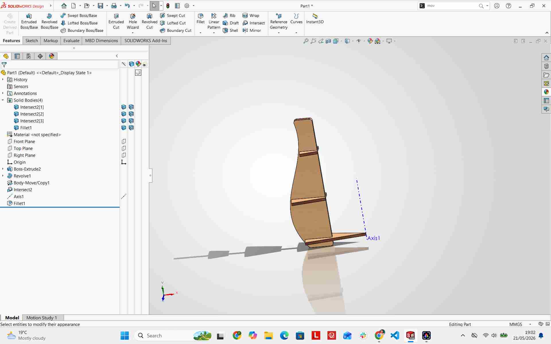
I used the Move/Copy Bodies tool to duplicate structural components around the central axis, then applied the Combine feature to integrate them into unified bodies.
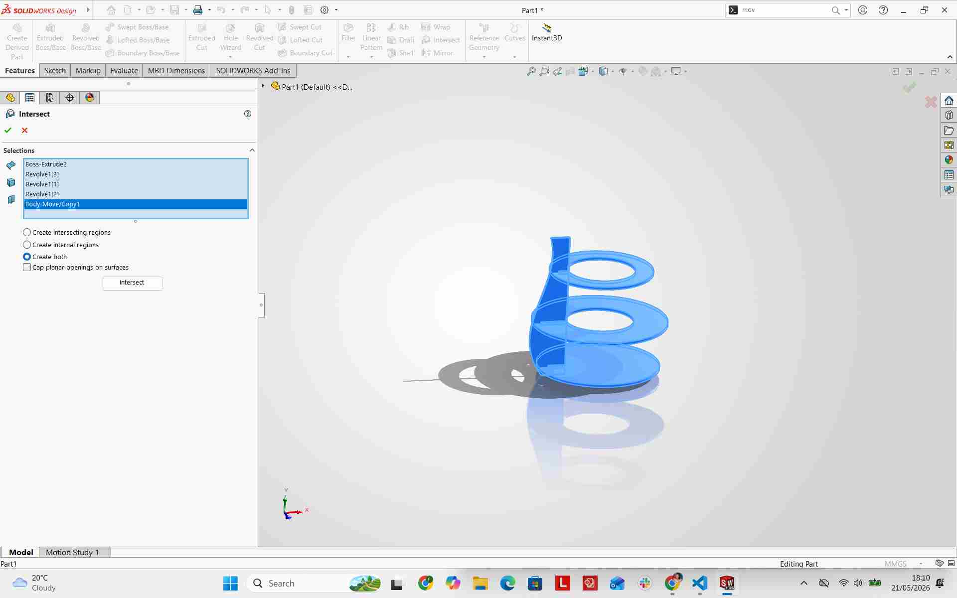
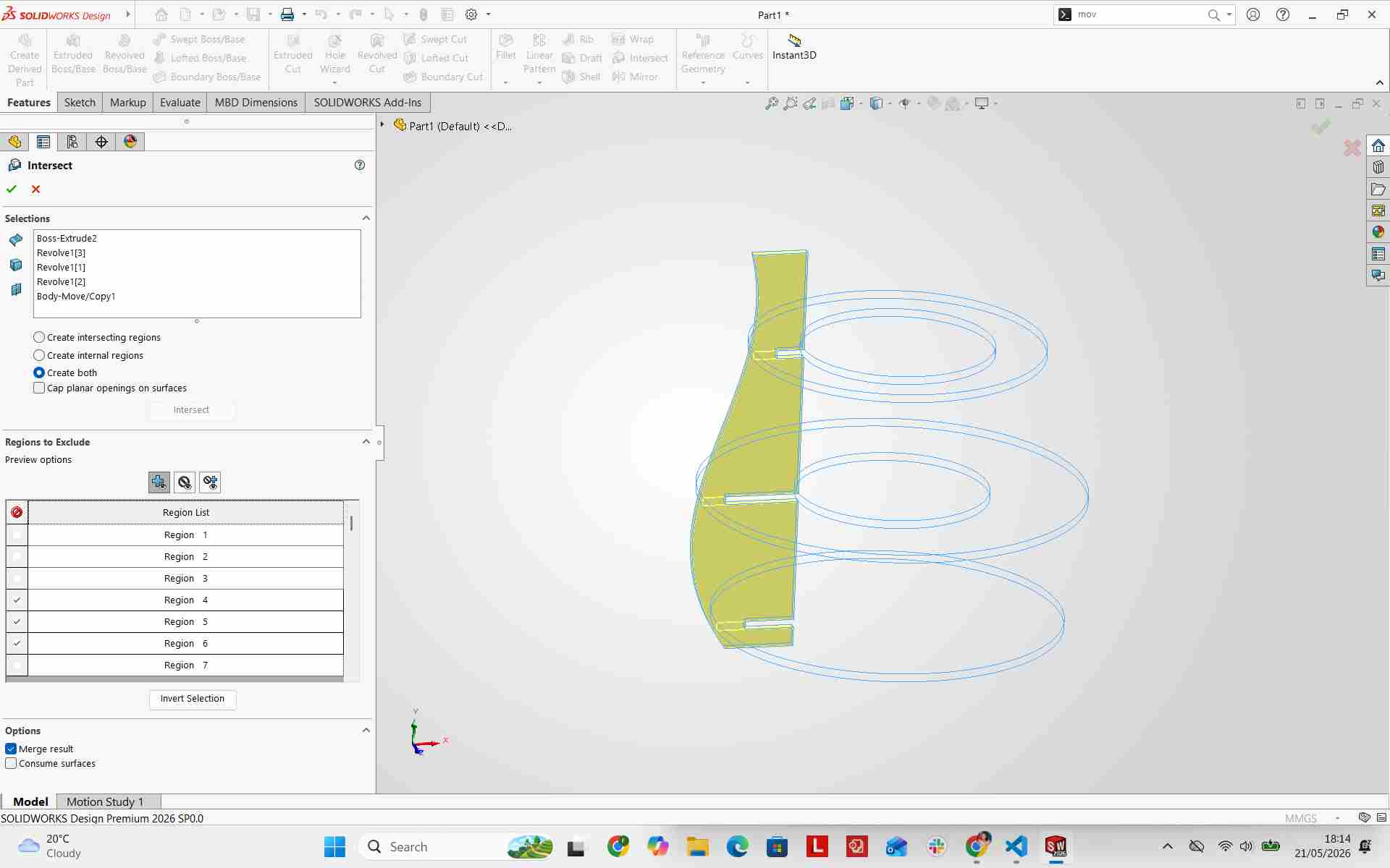
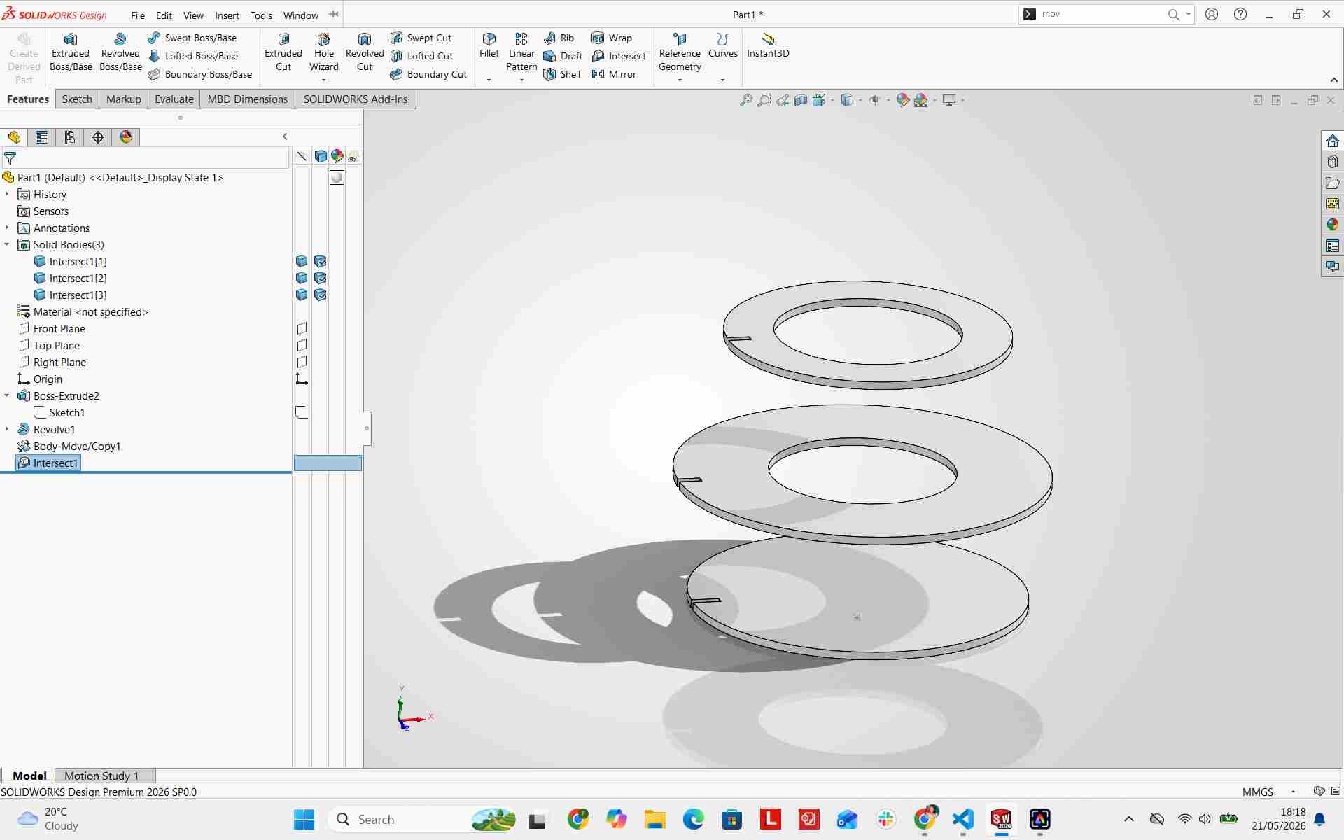
I performed an Intersect operation to generate the interlocking joint cutouts between vertical fins and horizontal rings.
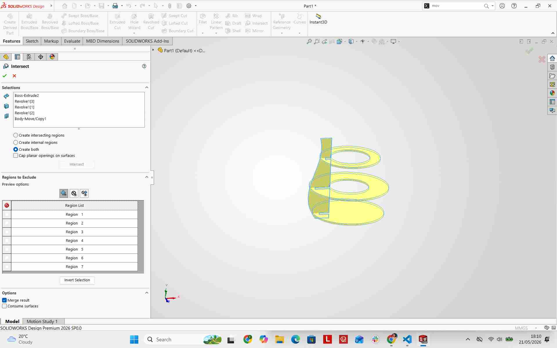
Excluding Regions
I excluded non-essential regions from the calculation to keep focus on the interlocking ring joints.
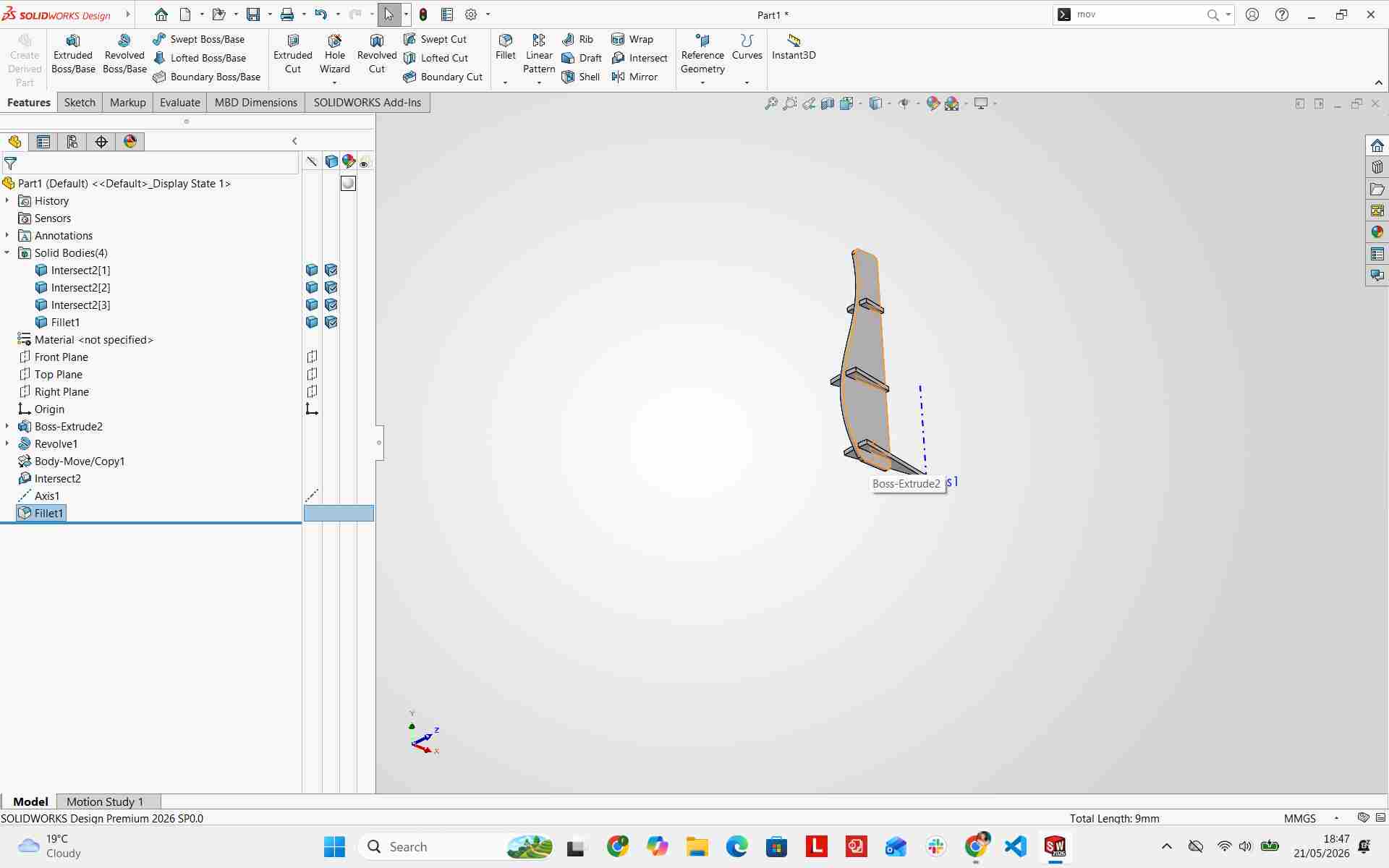
Adding Fillets
I rounded sharp edges on the base fin model using fillet features to improve aesthetic appeal and smooth assembly insertion.
Adding Material
I assigned a Cherry wood texture from the materials library to preview realistic assembly rendering.
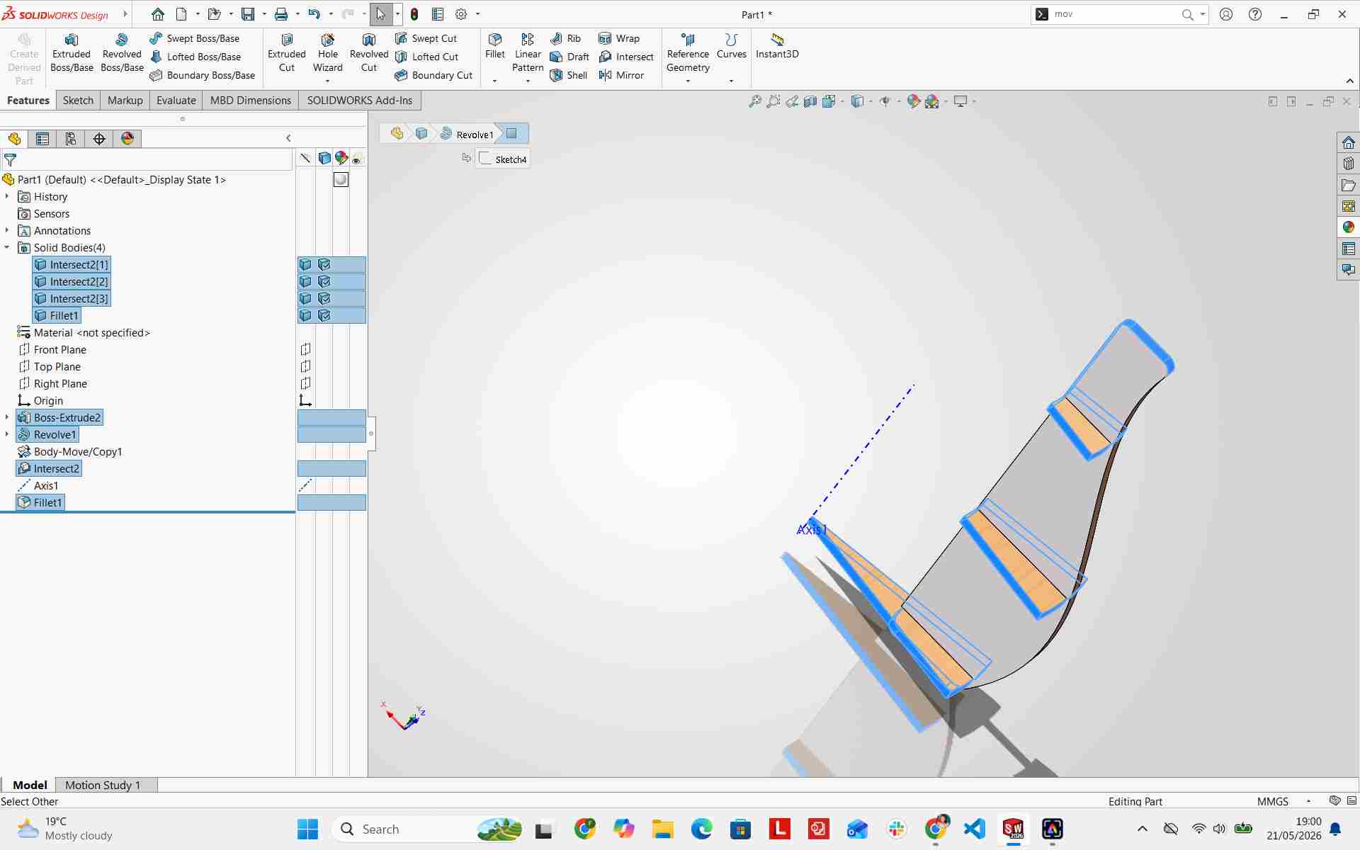
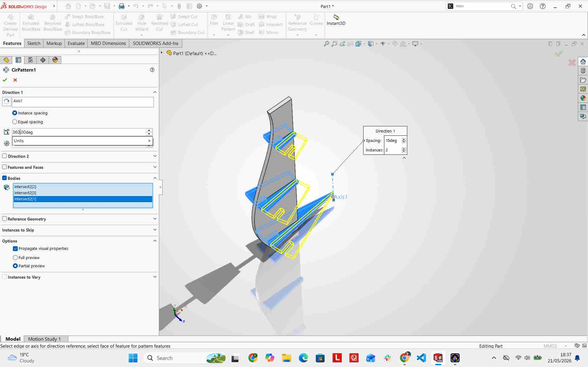
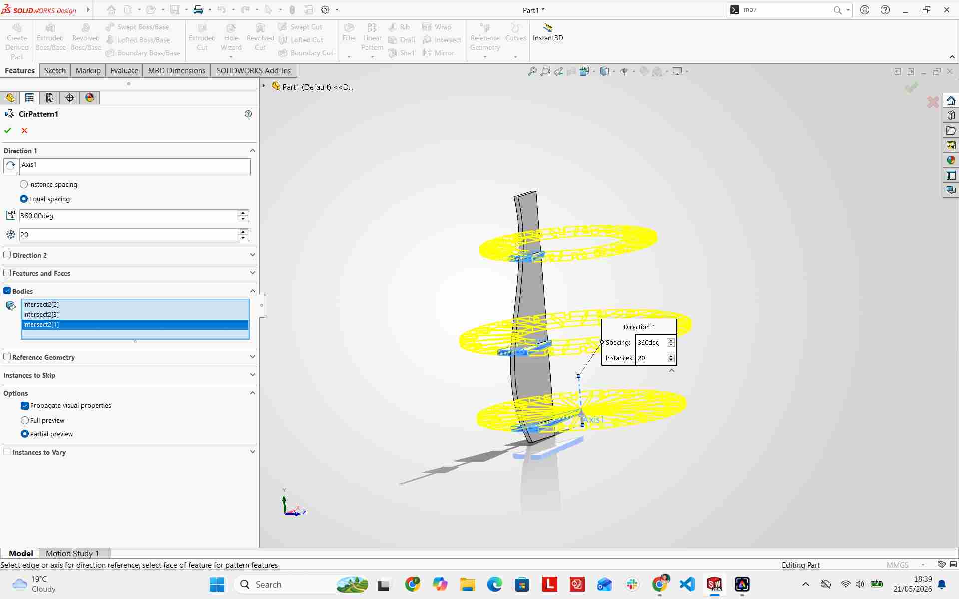
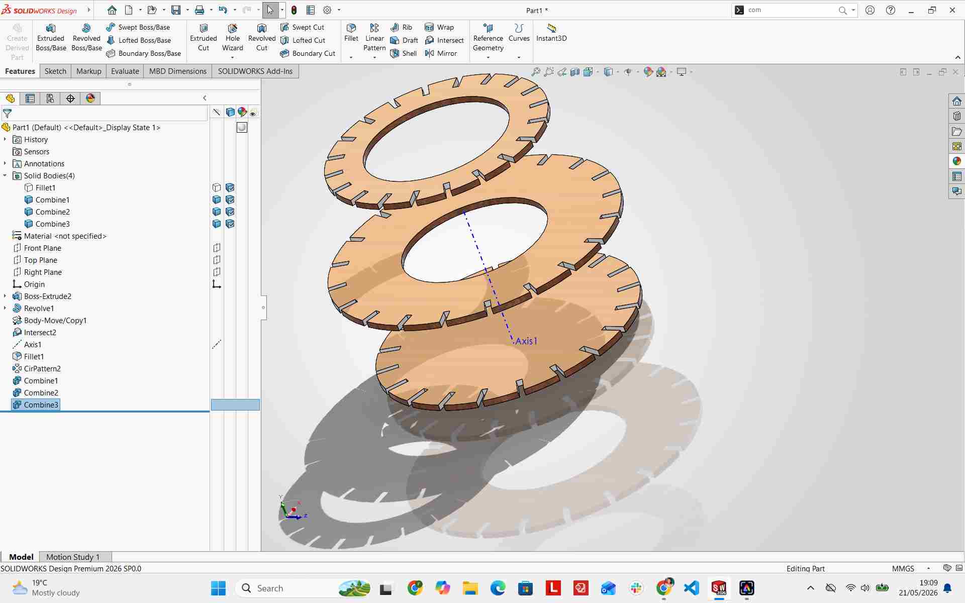
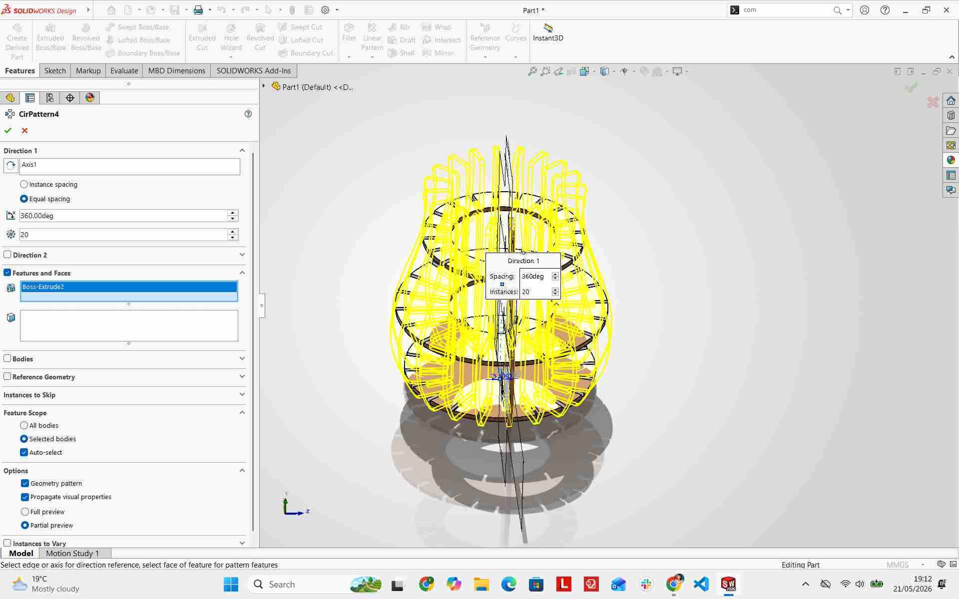
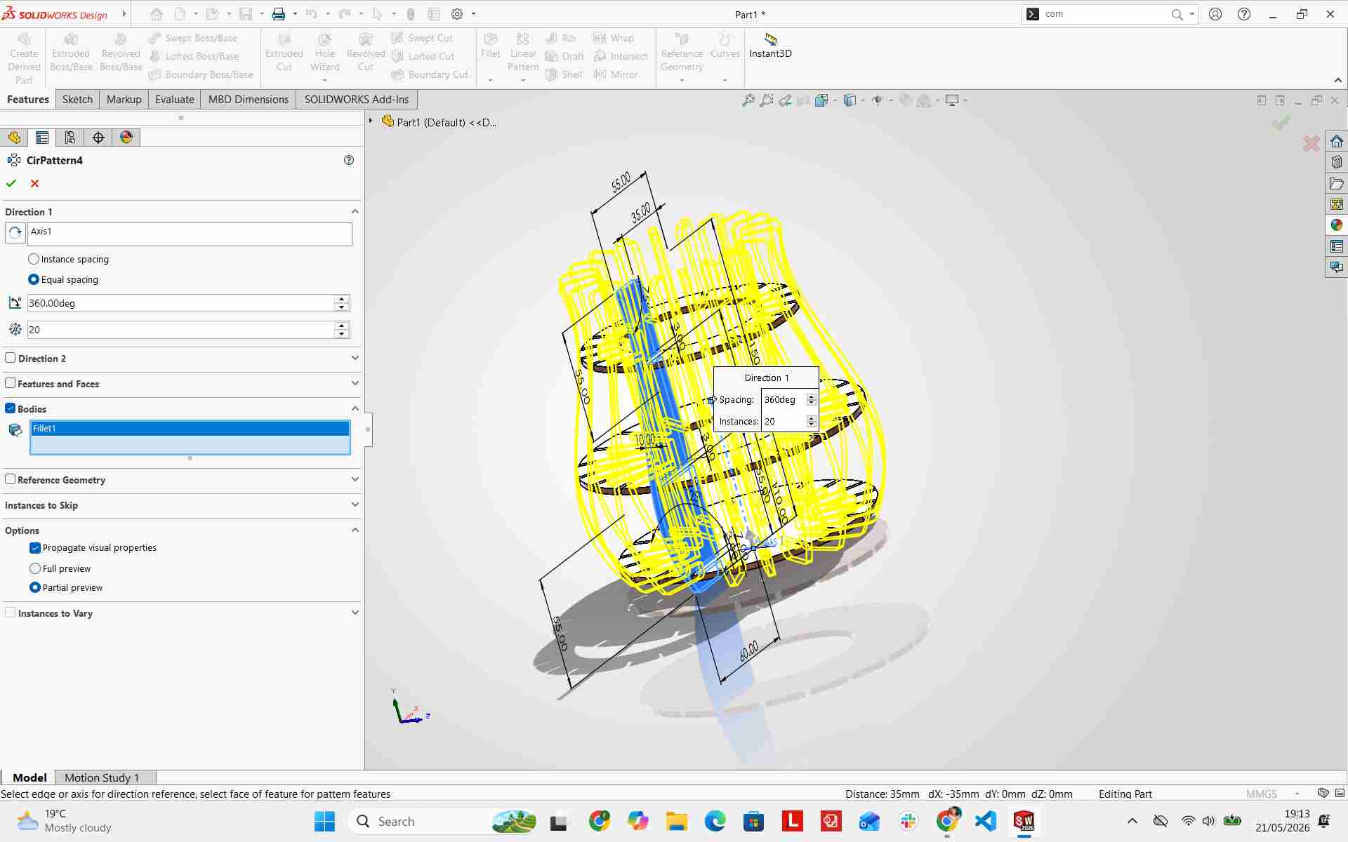
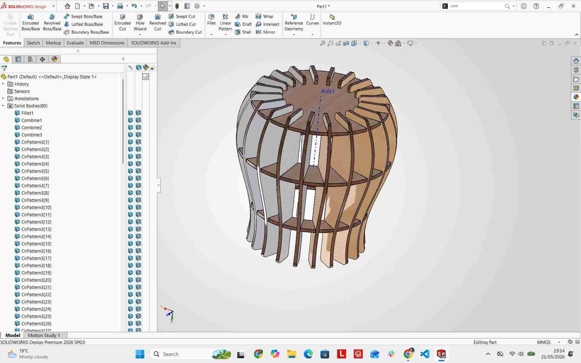
I expanded the rotational array from a 15-degree segment to a full 360-degree pattern, arranging 20 vertical fins along the circular rings.
Combining the Parts
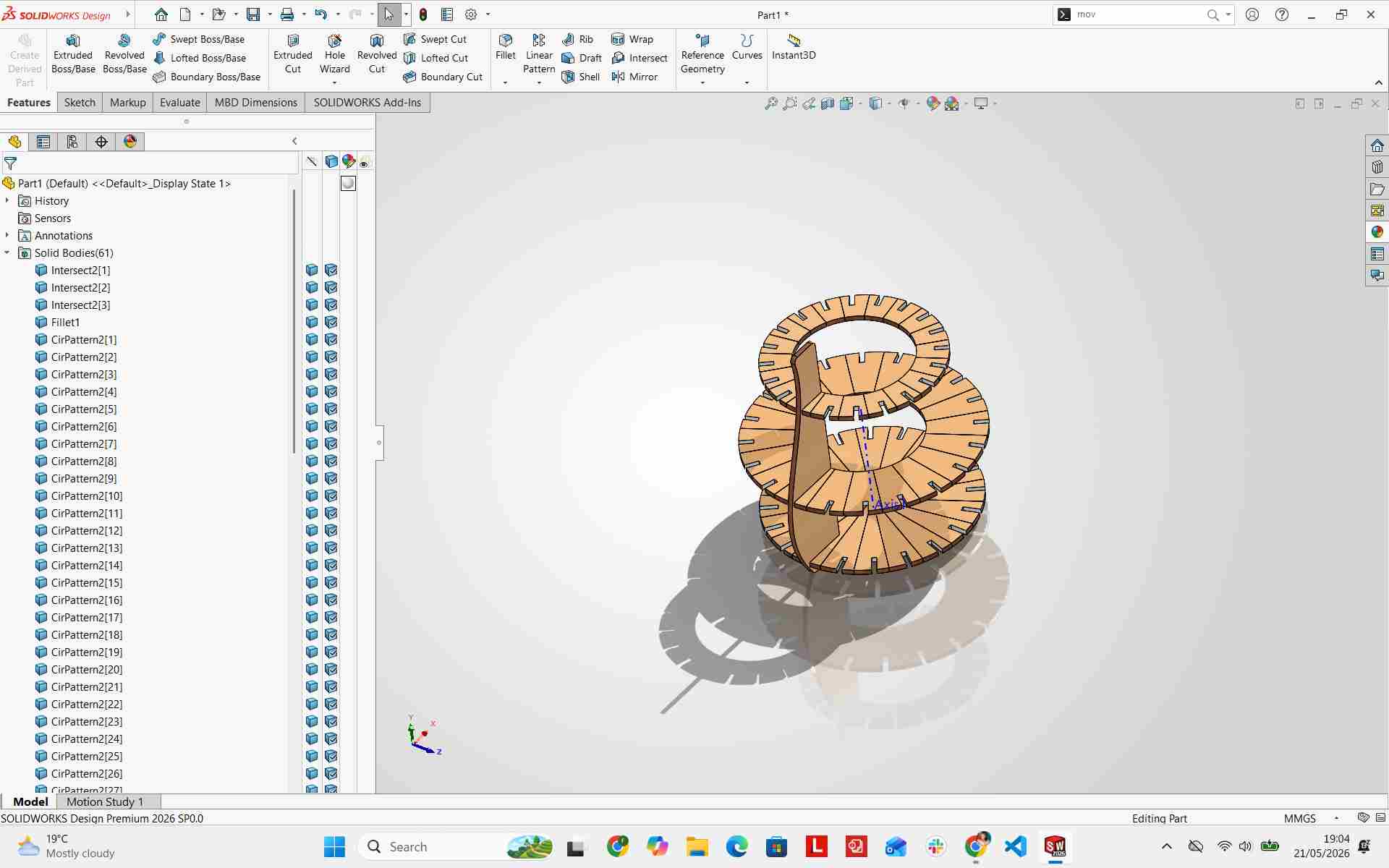
I combined individual ring segments into continuous solid bodies for seamless fabrication exporting.
Adding Final Details & Assembly Verification
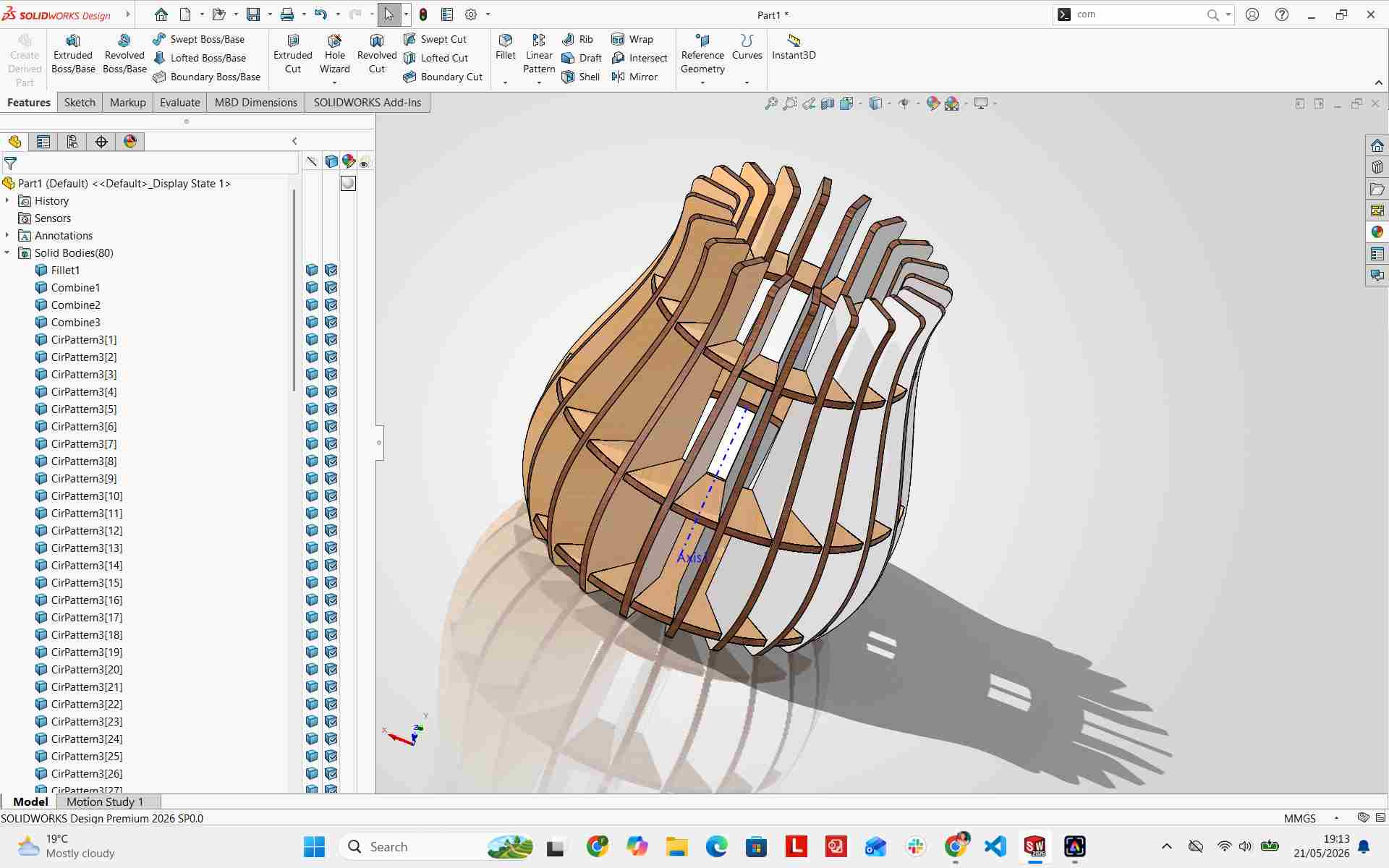
I performed a final virtual fit check to confirm proper alignment across all 20 fins and interlocking slots.
Final CAD Model
Exporting DXF Files
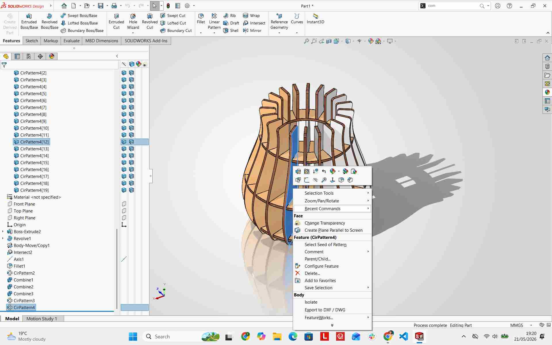
After completing the 3D model, I exported the individual flat component faces as DXF vector files for laser cutting preparation.
Preparing Laser Cutting Files in Inkscape
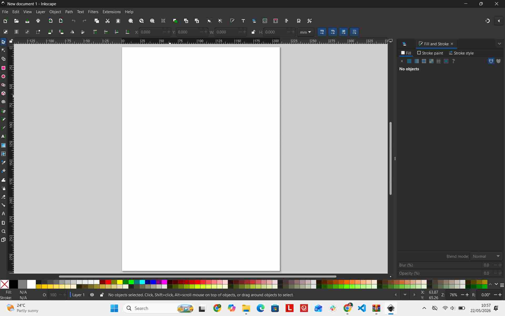
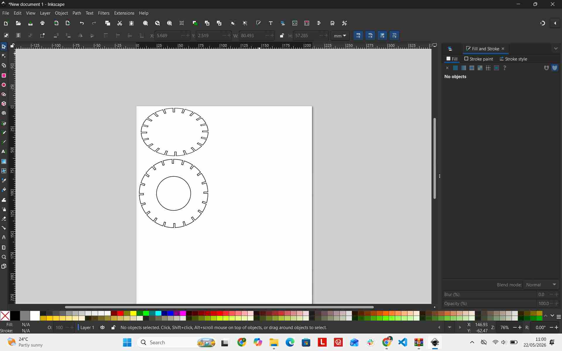
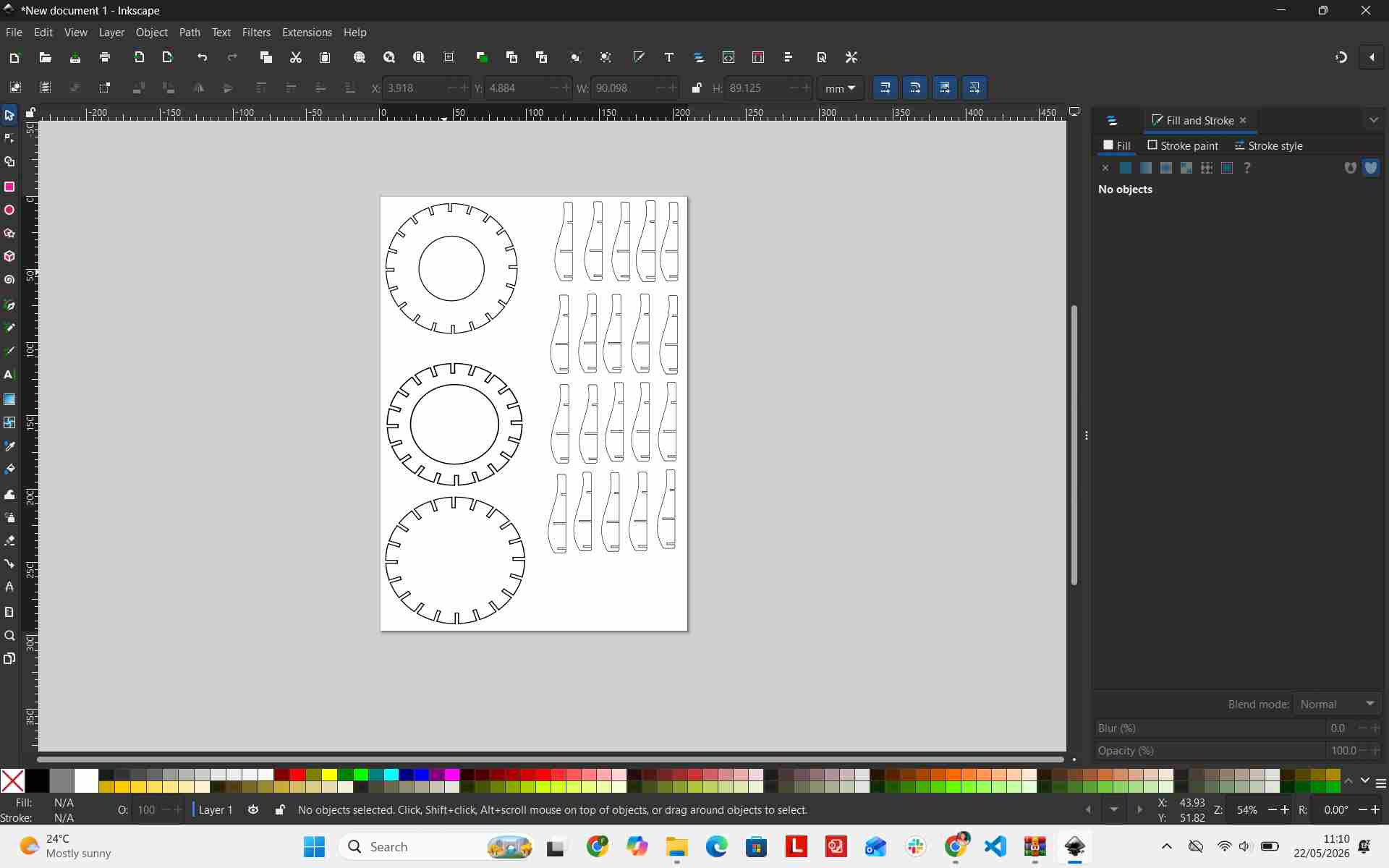
I arranged the exported DXF part profiles in Inkscape to format vector paths and maximize sheet nesting efficiency.
Working with the Laser Cutter
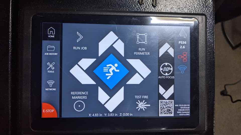
Depending on the laser cutter controller, vector files saved directly in DXF format can often be loaded straight into the web interface. Ensure the laser power is switched on, system checks pass, and the network IP address displays on the machine screen.
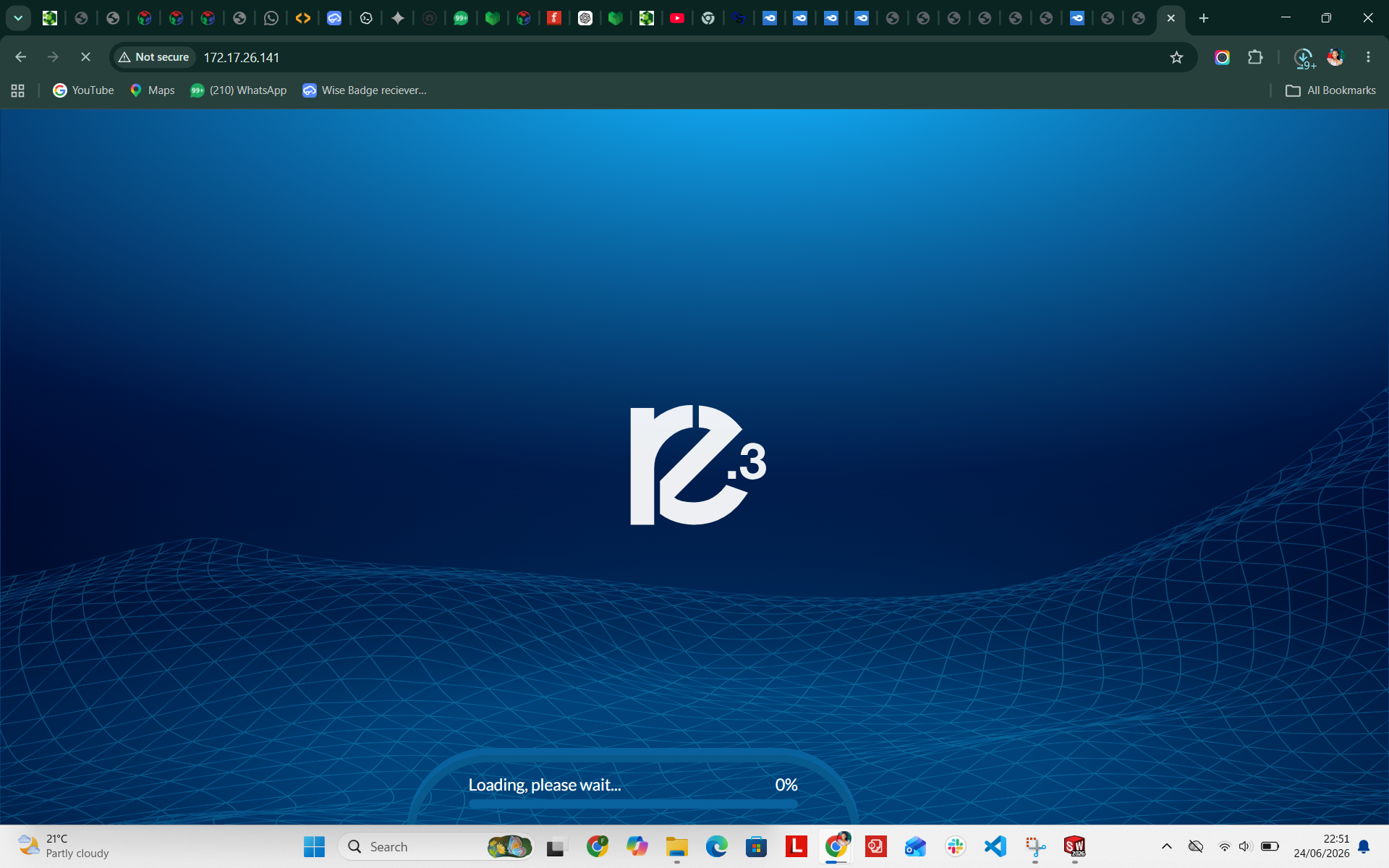
I opened Google Chrome on my laptop and navigated to the network IP displayed on the machine screen. Both the PC and laser cutter must be connected to the same local network.
After loading the web dashboard, I verified home positioning and origin coordinates. The laser's starting origin is marked by a red positioning diode on the physical bed.
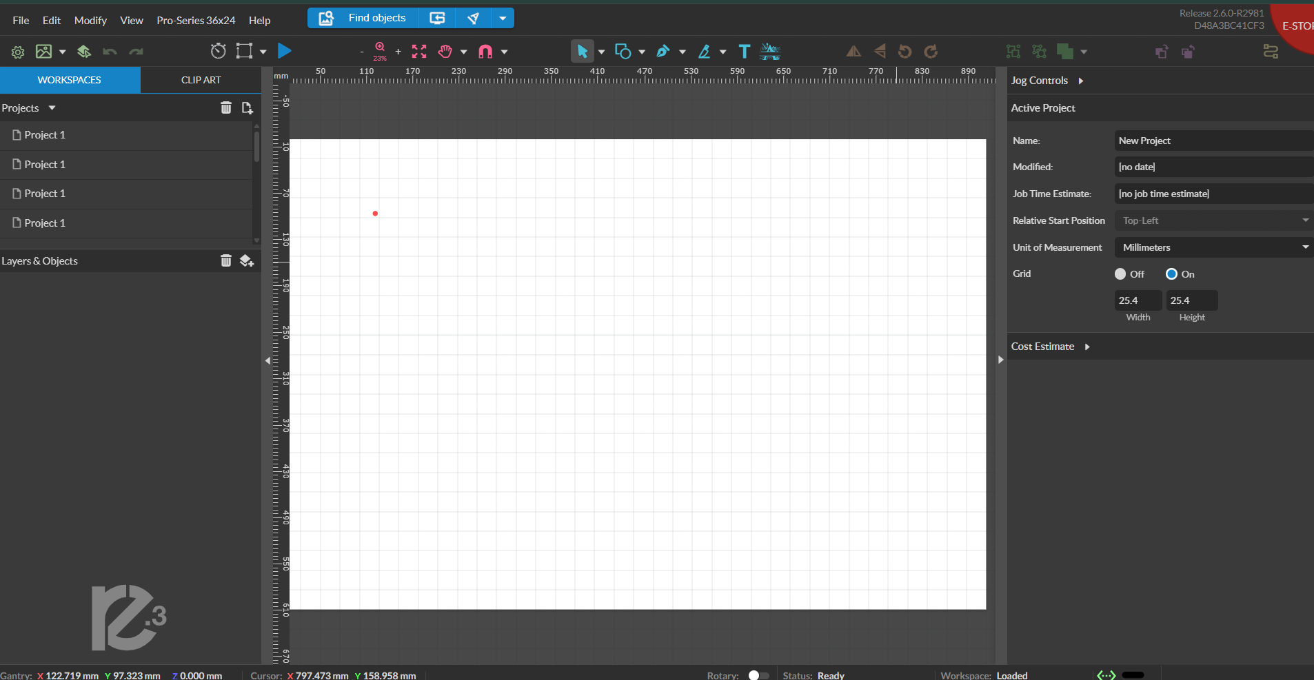
Using drag-and-drop, I imported the DXF files into the cutting layout canvas.
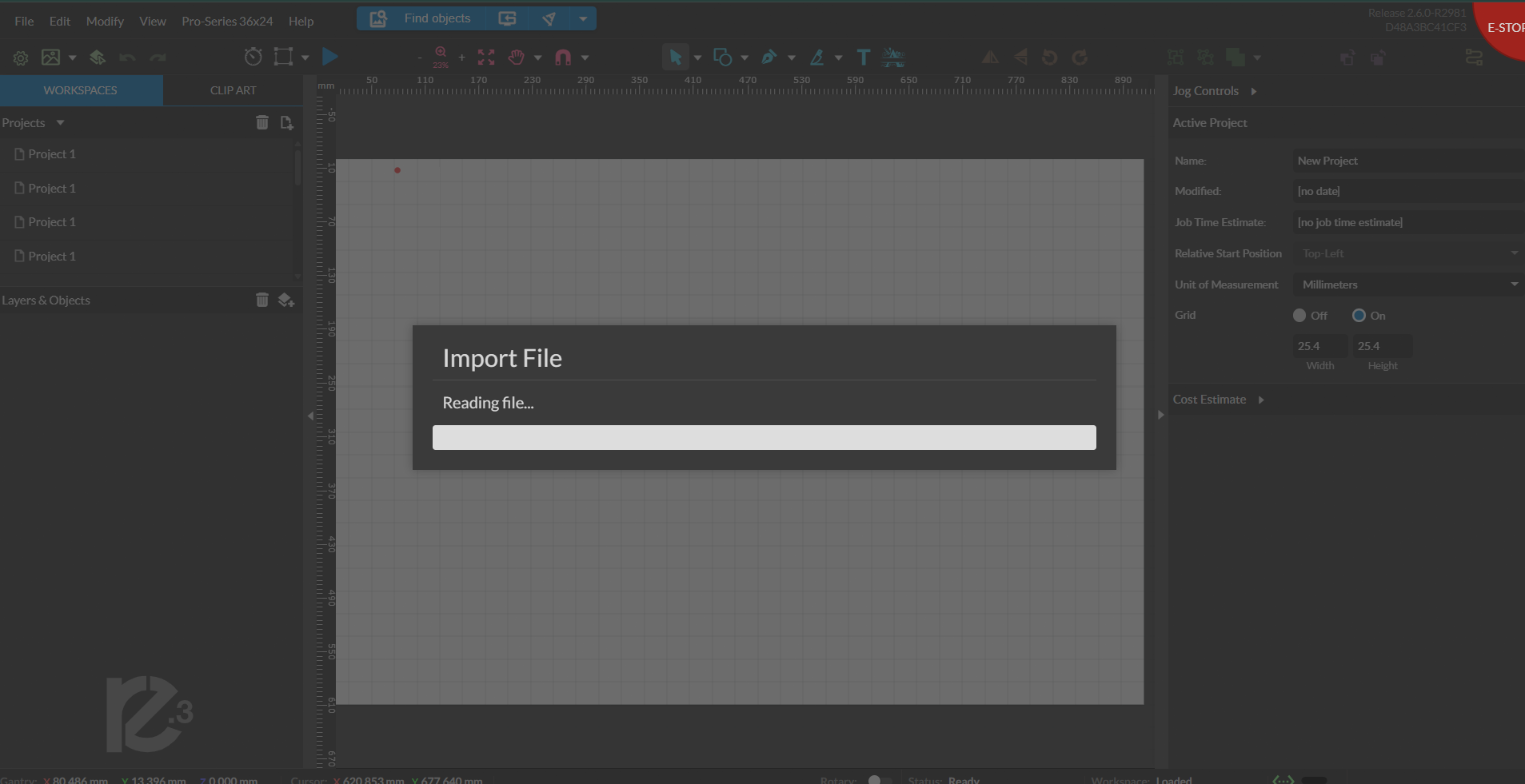
Because the stock material sheet was large enough, I arranged all required parts within a single cutting job.
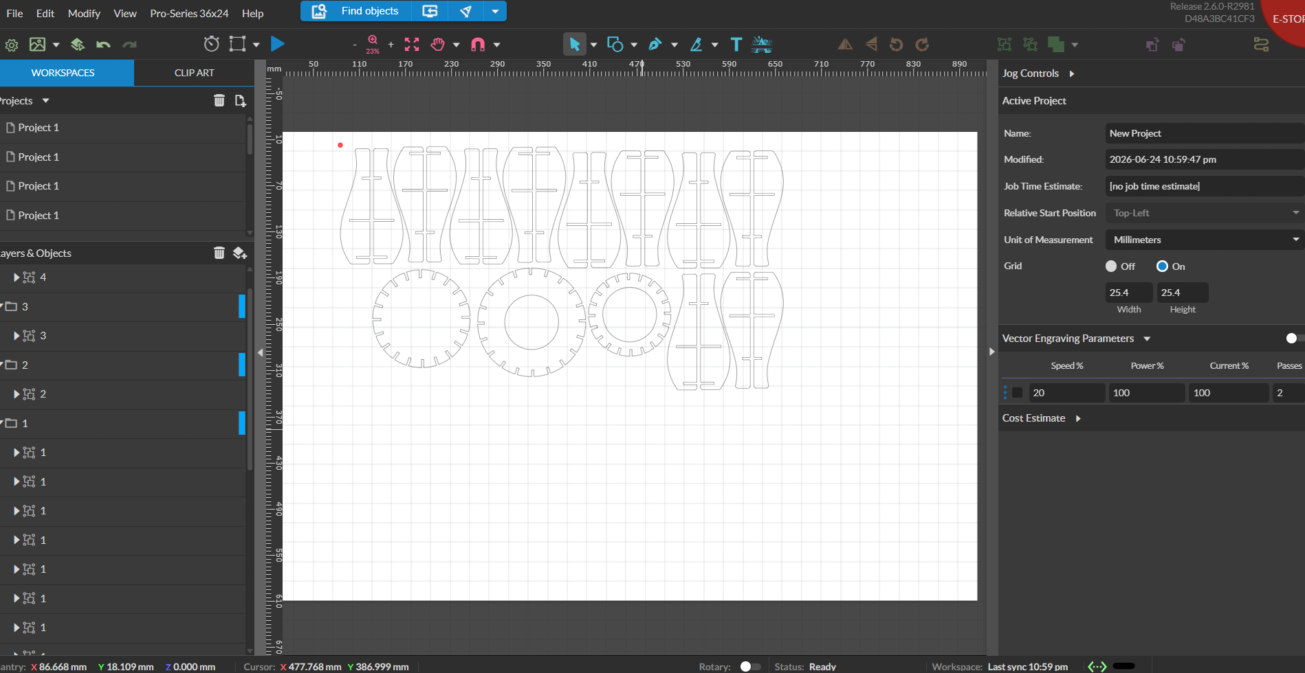
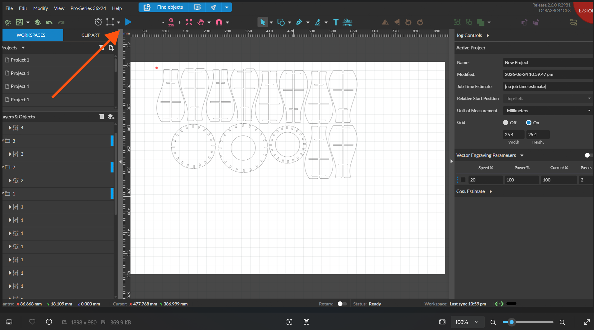
Clicking the blue Start button on the dashboard initiated the laser cutting job relative to the red dot reference point.
Full Laser Cutting Process Video
Parts Extraction and Assembly
Once cutting completed, all individual components were popped out cleanly from the cardstock/plywood sheet.

Design Extraction Video
Assembly Process Video
Interlocking the vertical fins into the horizontal support rings sequentially from base to top:
Final Product
The completed, fully assembled 3D press-fit waffle structure:
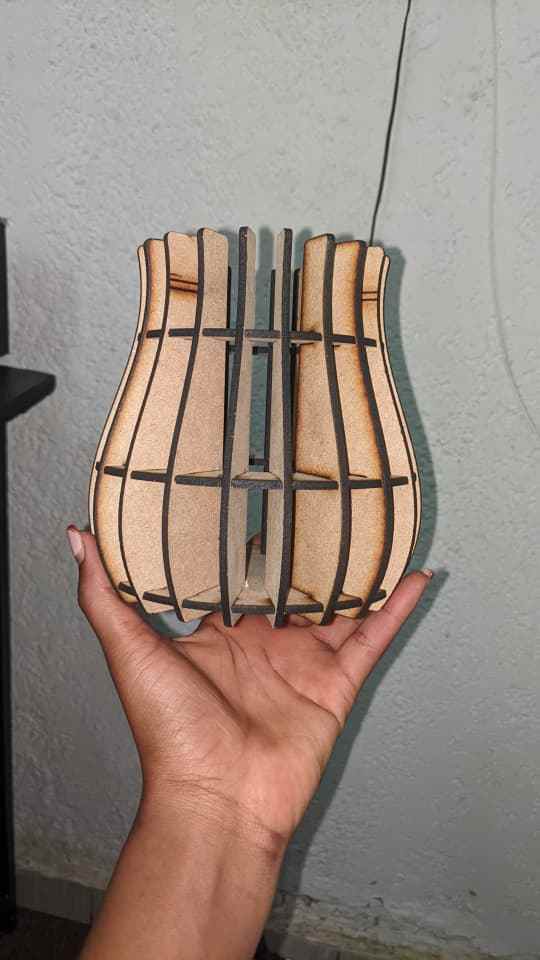
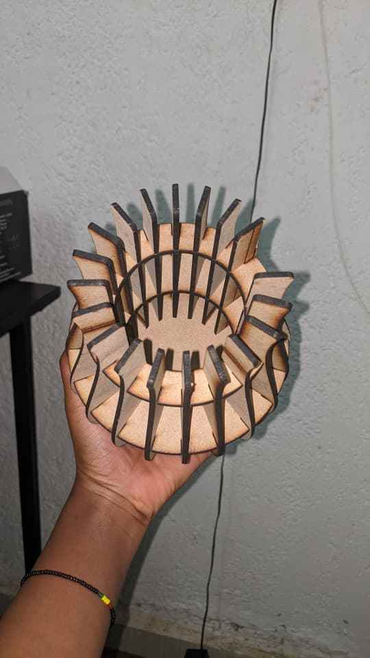
My Design at Work
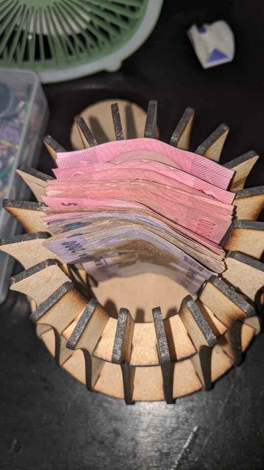
Vinyl Cutting
For the vinyl cutting assignment, I designed a vector graphic in Inkscape and prepared cut paths for the machine to score outdoor vinyl material.
Design Preparation
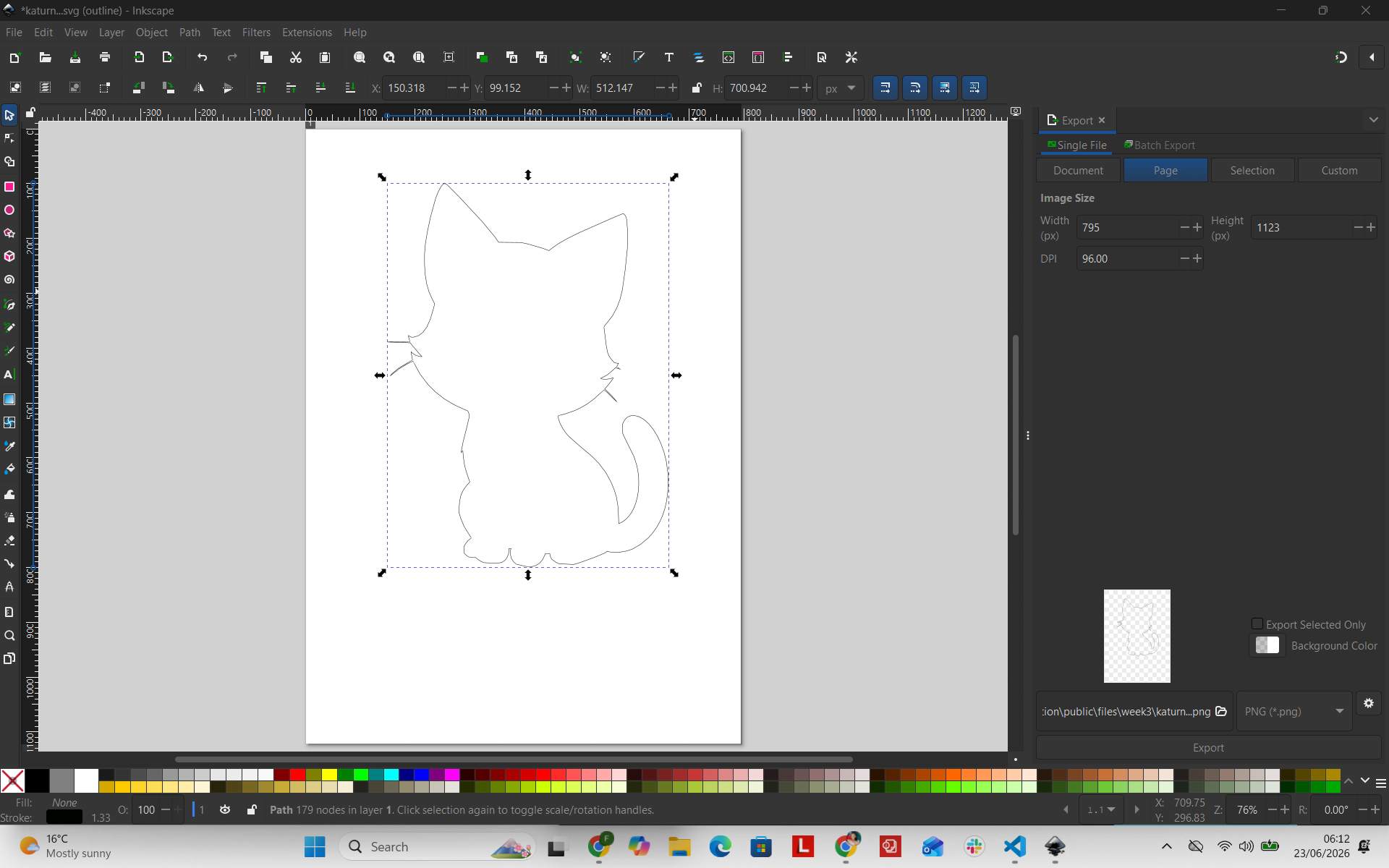
I reused the cartoon cat artwork from Week 02, imported the graphic into Inkscape, and converted vectors into clean single-stroke cut contours.
1. Initial State: Vector Graphic Loaded
The process started with vector paths active in the workspace canvas.
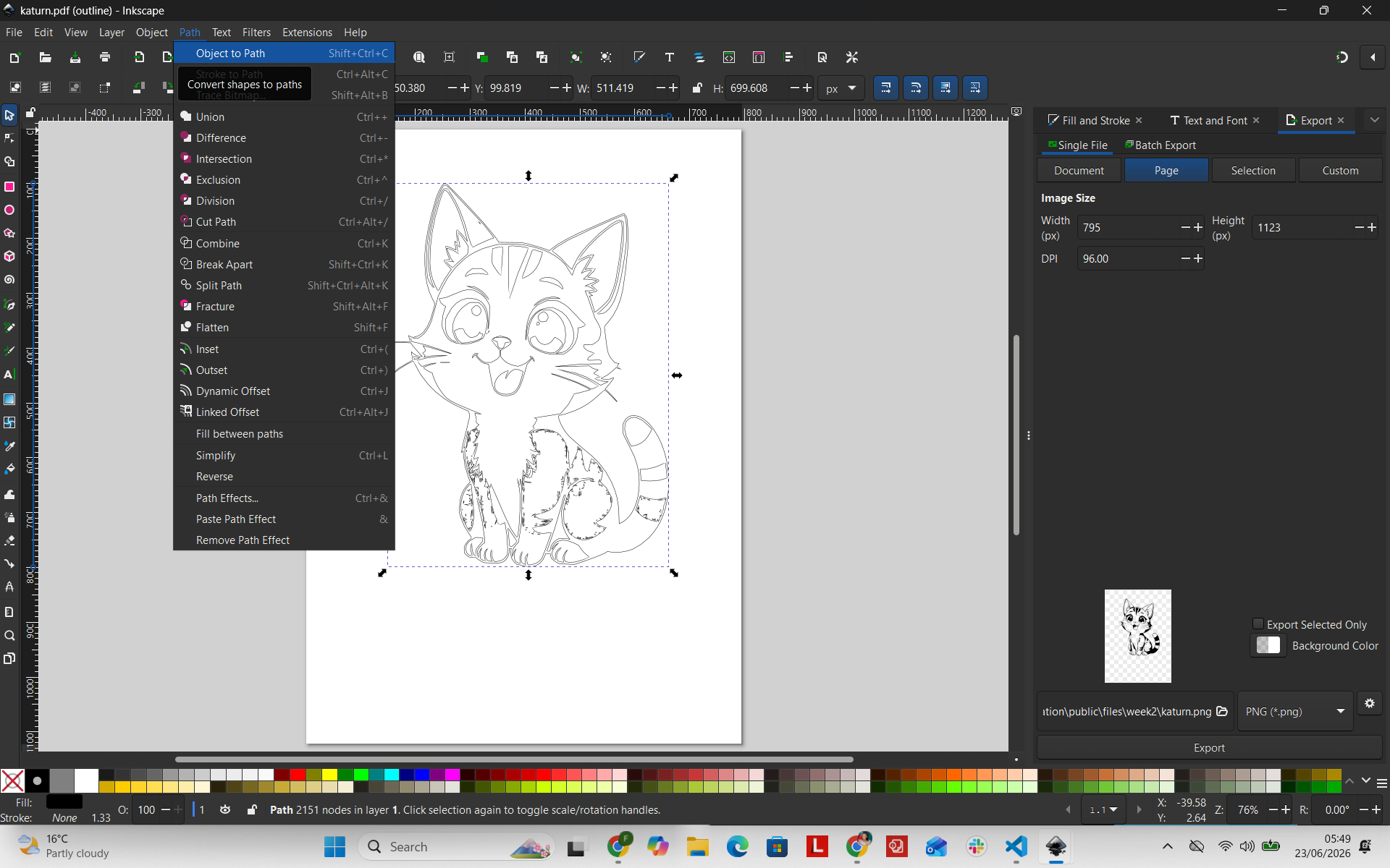
2. Duplicating Artwork
Using CTRL + D, I duplicated the vector geometry directly over the original path to keep a backup master copy.
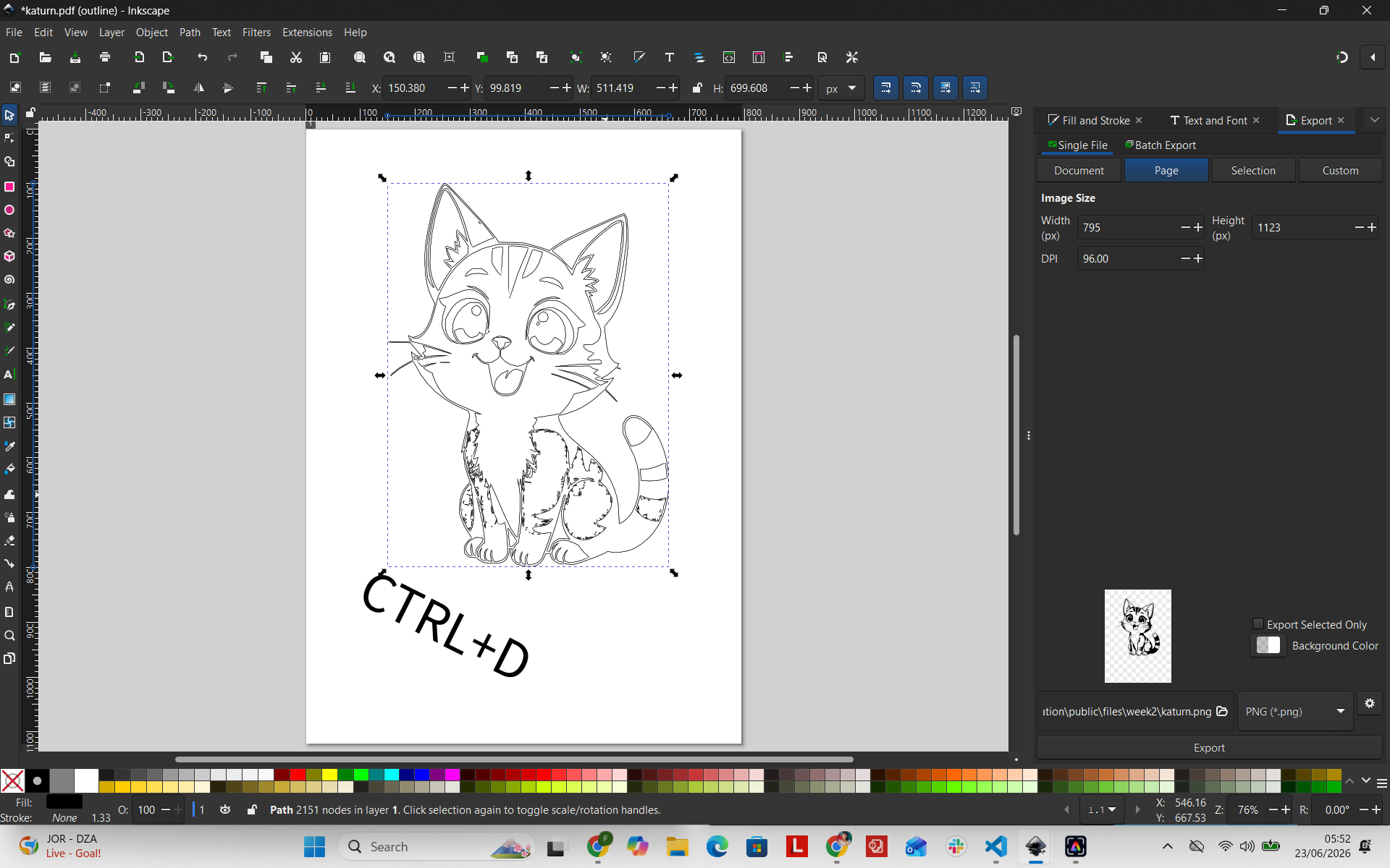
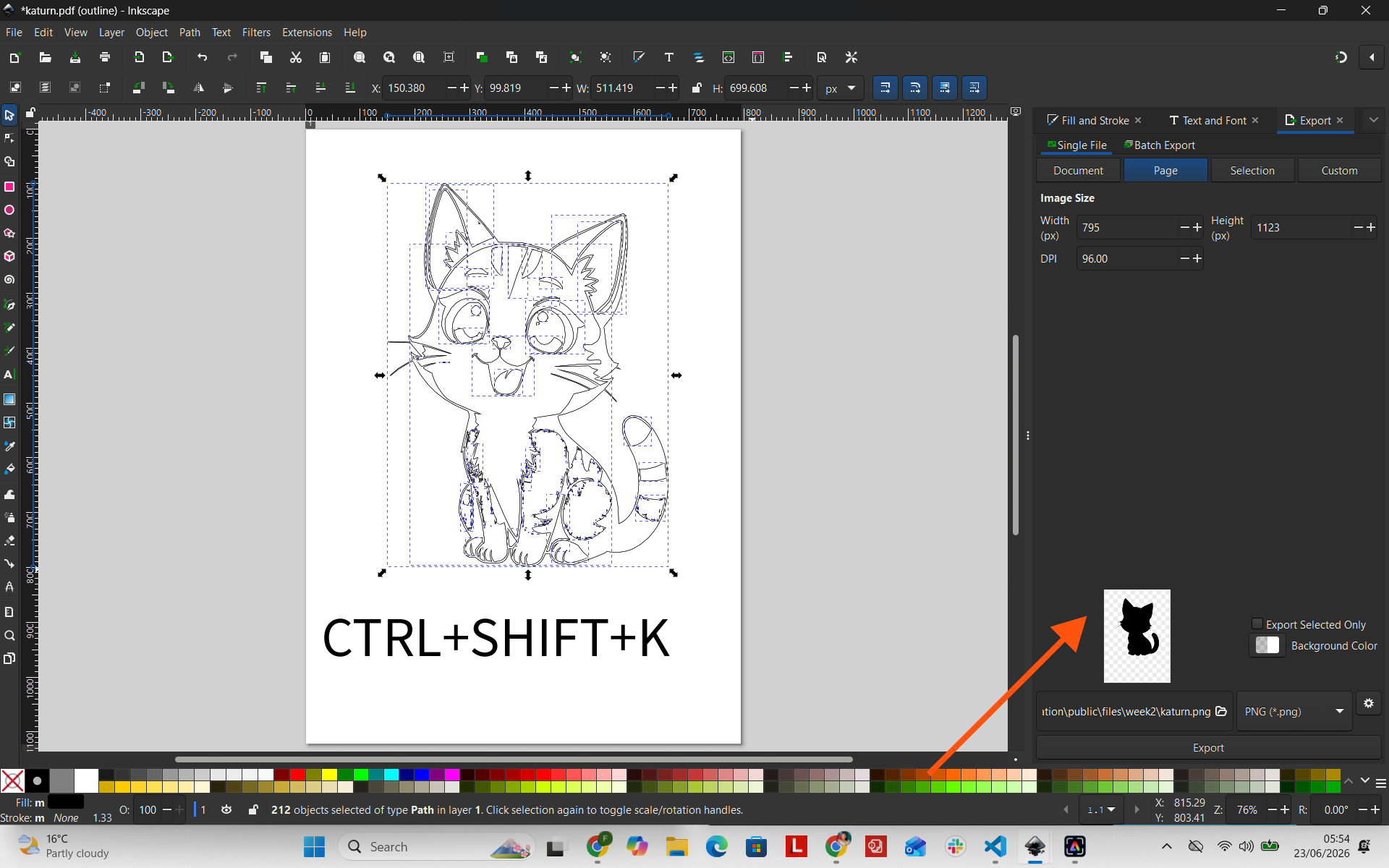
3. Breaking Vector Paths Apart
With the duplicated layer highlighted, I selected Path → Break Apart (SHIFT + CTRL + K) to separate complex compound paths into distinct closed outlines.
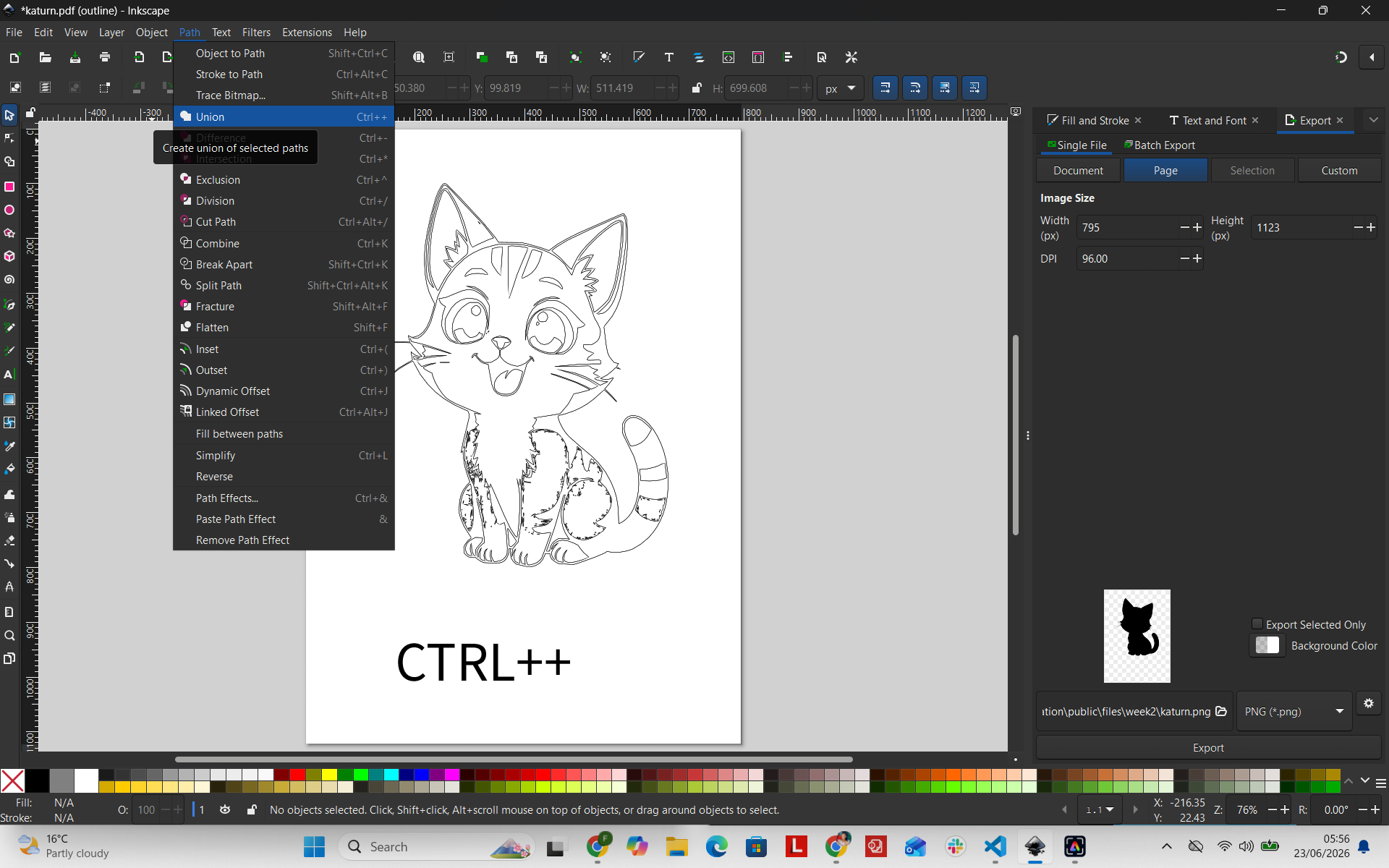
4. Uniting Shapes into a Silhouette
To merge overlapping shapes into a single perimeter boundary, I applied a Boolean union via Path → Union (CTRL + +).
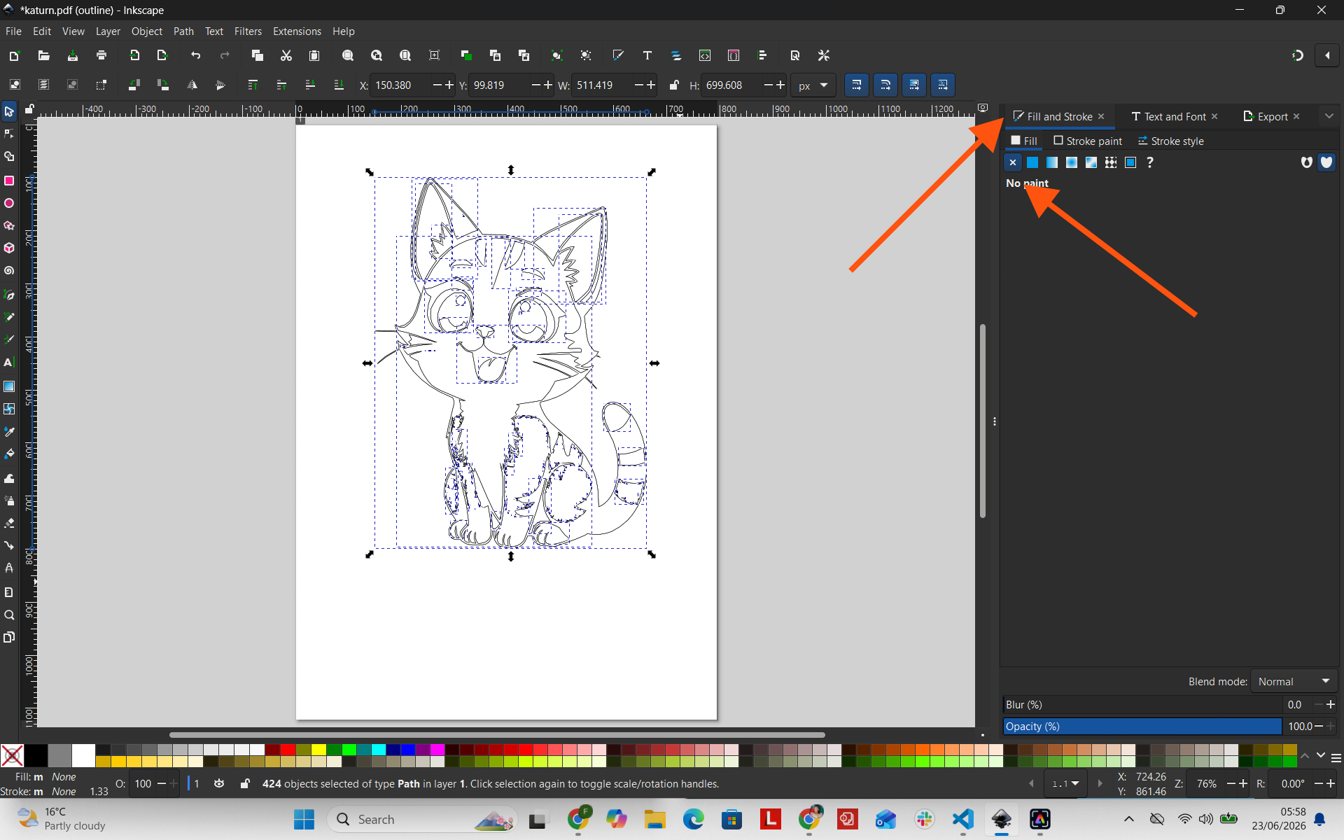
5. Removing the Fill
To isolate the blade trajectory, I opened the Fill and Stroke menu and disabled solid fills by selecting No Paint (X).
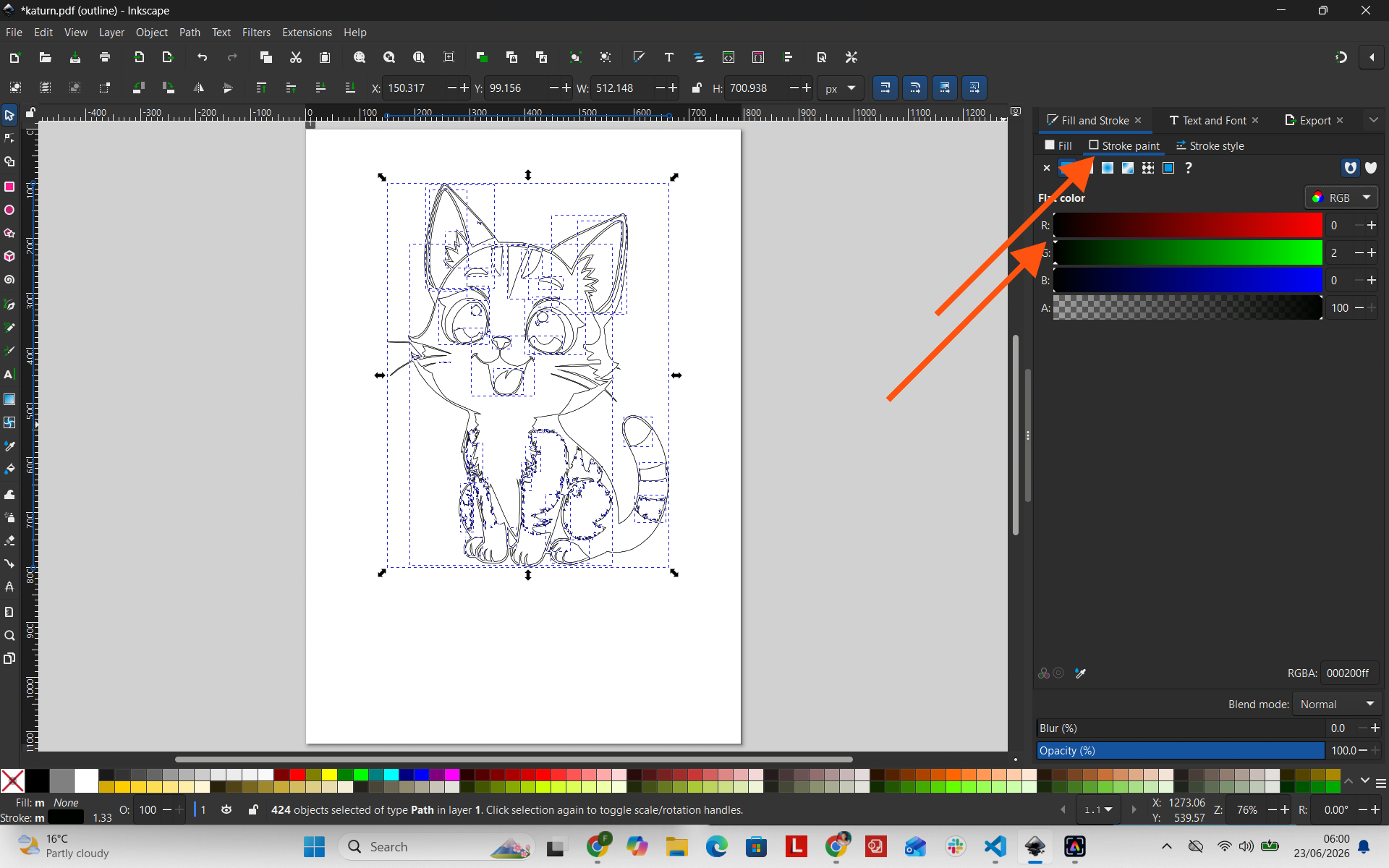
6. Applying Stroke Outline
Under the Stroke Paint menu, I enabled a solid flat stroke color. This created a single continuous perimeter line for the vinyl cutter blade to follow.
Vinyl Cutter Settings
- Blade Depth: Medium extension setting
- Force: Calibrated for standard adhesive vinyl
- Speed: Medium speed for fine detail accuracy
Result
The vinyl cut yielded crisp, accurate edges. Properly closing vector paths and removing redundant overlapping strokes prevents blade drag and tearing during cutting.
Cutting & Application Workflow
- Imported vector SVG paths into the vinyl spooler software.
- Adjusted cutting force parameters relative to material liner backing.
- Executed the plot cutting program on the machine.
- Weeded away negative unneeded vinyl surrounding the silhouette.
- Applied masking transfer tape to lift and apply decal onto target surface.
Challenges & Problem Solving
Accurately compensating for kerf was the main challenge. Small variations in laser kerf significantly affected joint clearance and press-fit friction holding strength. Precise digital caliper material thickness measurement was essential for success.
What I Learned
I learned how parametric design variables dynamically adapt to real stock material variations, how laser cutter speed/power settings dictate edge finish, and why kerf offset compensation is indispensable when creating press-fit interlocking assemblies. I also built confidence in executing safe material handling protocols across laser and vinyl cutting equipment.
Hero Shots