// Week 02
Computer-Aided Design
Introduction
In Week 02, I focused on exploring various computer-aided design (CAD) tools to model both raster and vector images, as well as 2D and 3D models. The objective was to create a possible final project design, compress images and videos for documentation, and share the design files. This week was crucial for understanding how to visualize and plan a project using digital tools before fabrication.
Objectives & Strategy
Model (raster, vector, 2D, 3D, render, animate, simulate, ...) a possible final project, compress images and videos, and post a description with design files. This assignment focuses on exploring different digital design approaches to plan and visualize a final project before fabrication.
Design Strategy
Before opening any CAD software, I defined the objectives of the design process. The goal was not simply to learn different software packages, but to understand how each design approach contributes to digital fabrication.
- Create vector graphics suitable for laser cutting and documentation.
- Create raster graphics for image editing and presentation.
- Develop parametric 3D models that can later be manufactured.
- Evaluate different CAD software based on workflow and capabilities.
- Produce optimized media for fast-loading web documentation.
Instead of relying on only one software package, I intentionally explored multiple CAD environments so I could understand their strengths, limitations, and appropriate use cases.
Requirements
- Model raster graphics
- Model vector graphics
- Create 2D and 3D CAD designs
- Render a model
- Create an animation
- Compress images and videos
- Share design files
Tools & Software Comparison
Design Tools Selection
To complete this assignment, I explored different 2D and 3D design tools and evaluated them based on usability, precision, and output quality.
- Inkscape: Considered as an alternative for vector-based technical drawings.
- GIMP: Used it for modeling the raster images.
- SolidWorks: Used for 3D modeling of the electronic enclosure and structural components.
- FreeCAD: Used for 3D modeling of my final project, helping to convert the 2D design into a detailed 3D representation for visualization and future fabrication.
CAD Software Comparison
| Software | Type | Advantages | Limitations |
|---|---|---|---|
| Inkscape | Vector | Free, SVG support | Limited advanced illustration tools |
| GIMP | Raster | Powerful image editing | Not vector based |
| SolidWorks | 3D CAD | Professional and precise | Commercial software |
| FreeCAD | 3D CAD | Open source | Less polished interface |
Process & Documentation
Using Inkscape and GIMP to Model 2D Vector and Raster Images
Choosing Inkscape and GIMP for 2D modeling workflows provides a 100% free, open-source ecosystem that completely eliminates the recurring subscription costs of proprietary software like Adobe Creative Cloud. When paired together, they form a production pipeline that matches the capabilities of expensive corporate suites.
Design Approach
To approach this task, I first explored different design strategies. Two main approaches were considered:
- Using vector tools like Inkscape for technical drawing
I chose Inkscape because it allows better alignment, faster workflow, and produces a clean and modern layout suitable for documentation.
GET Inkscape
I have previously downloaded and installed Inkscape on my local PC, but if you want to access it you can download it from the official website: Download Inkscape v1.4.2
After downloading it, you can install it by following the installation instructions provided on the website.
Using Inkscape to Model Vector Image
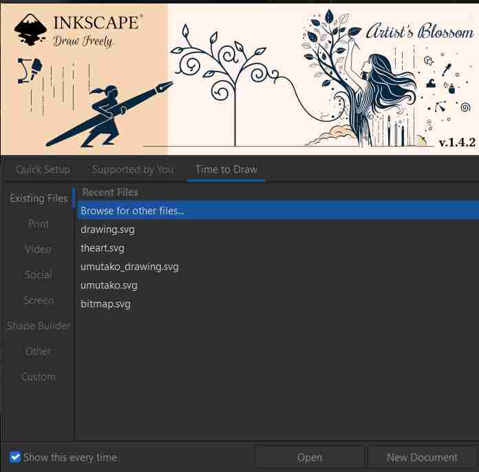
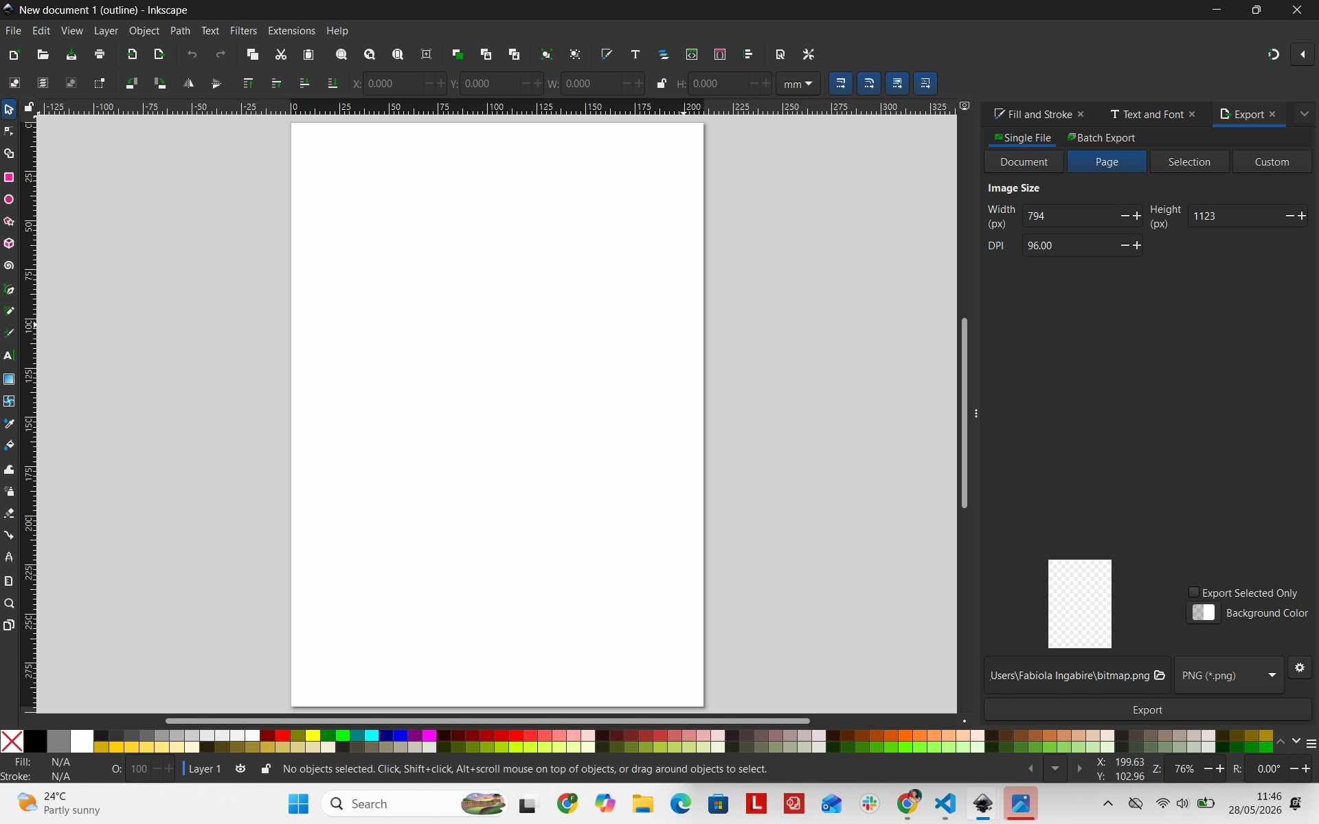
Here is the Inkscape opening screen where I modeled the vector image for the foundational visualization of my final project, including key sections in that design.
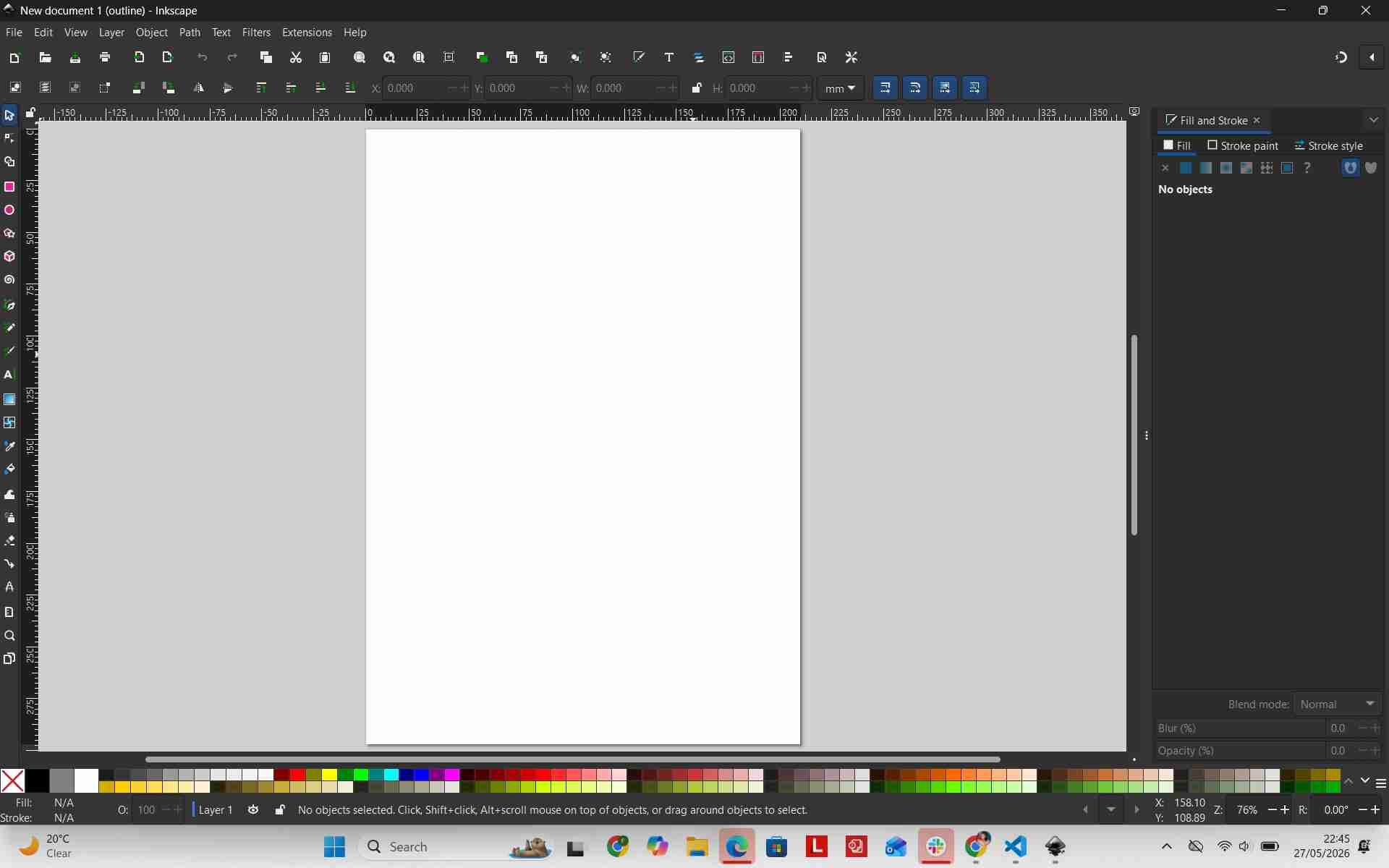
I opened a new file in Inkscape to start designing the vector image and set the canvas dimensions to 2000px × 2000px to ensure adequate design space and high export quality.
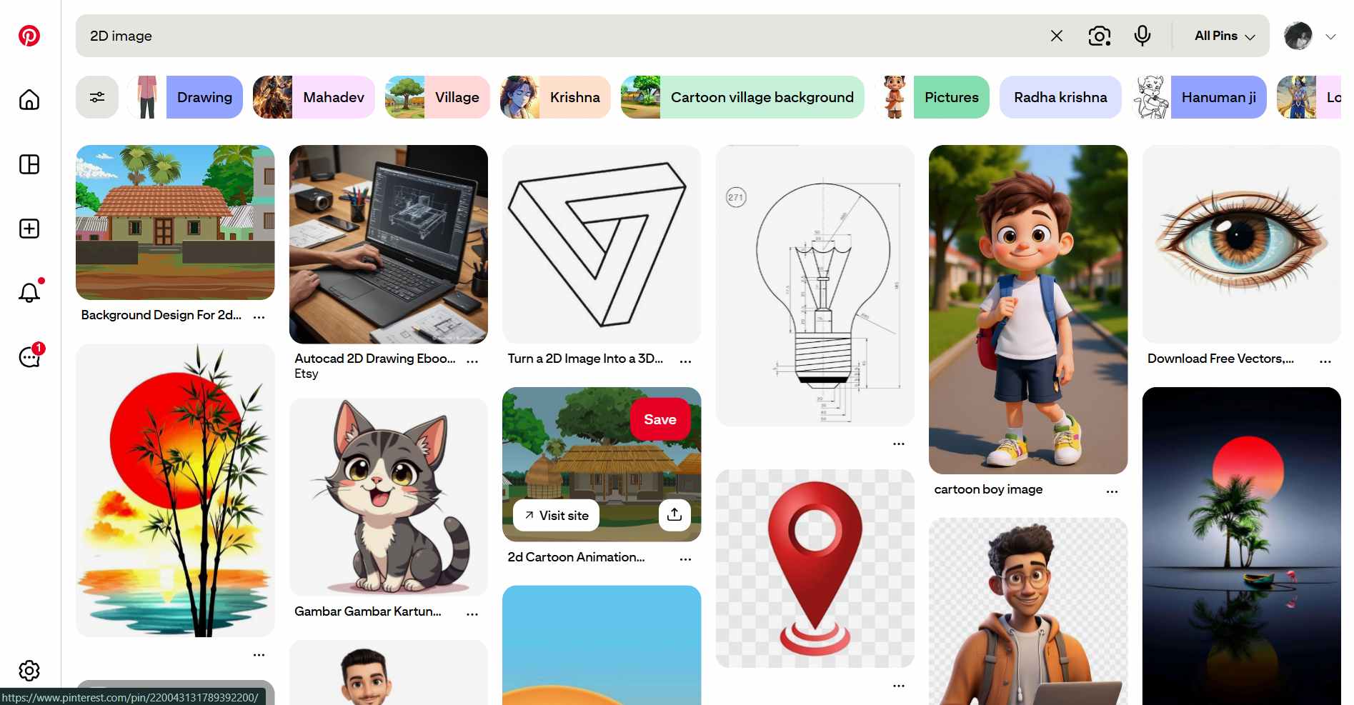
To become familiar with tools like Inkscape and GIMP, I decided to work on different images: one being my 2D final project designed from scratch, and another being a cartoon image downloaded from Pinterest: Download image from Pinterest.
I opened Pinterest online and searched for an image, choosing a cartoon cat design.
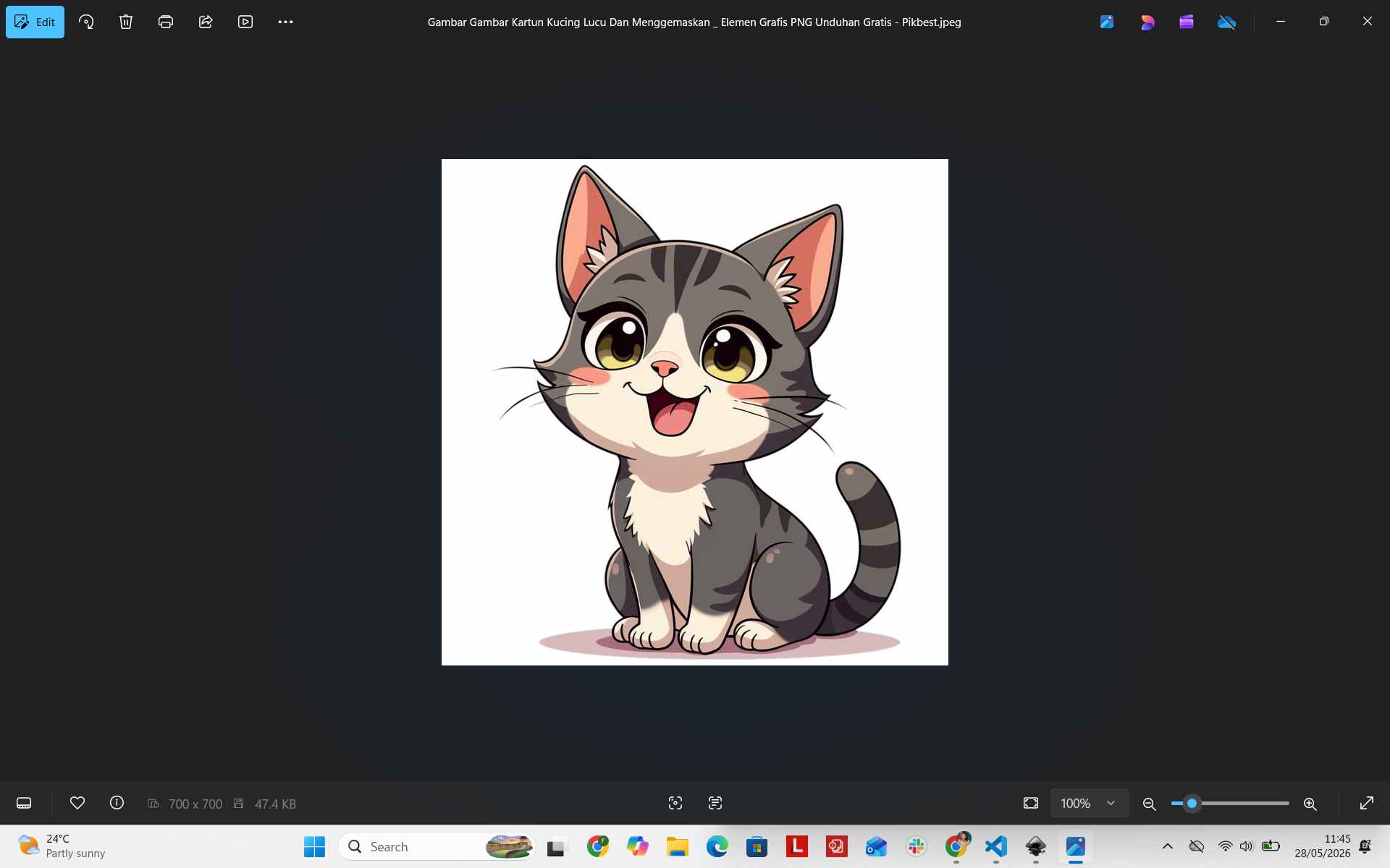
I downloaded the image locally to ensure proper file access.

After downloading, I verified the file on my computer.
Next, I launched Inkscape to model the vector graphic.
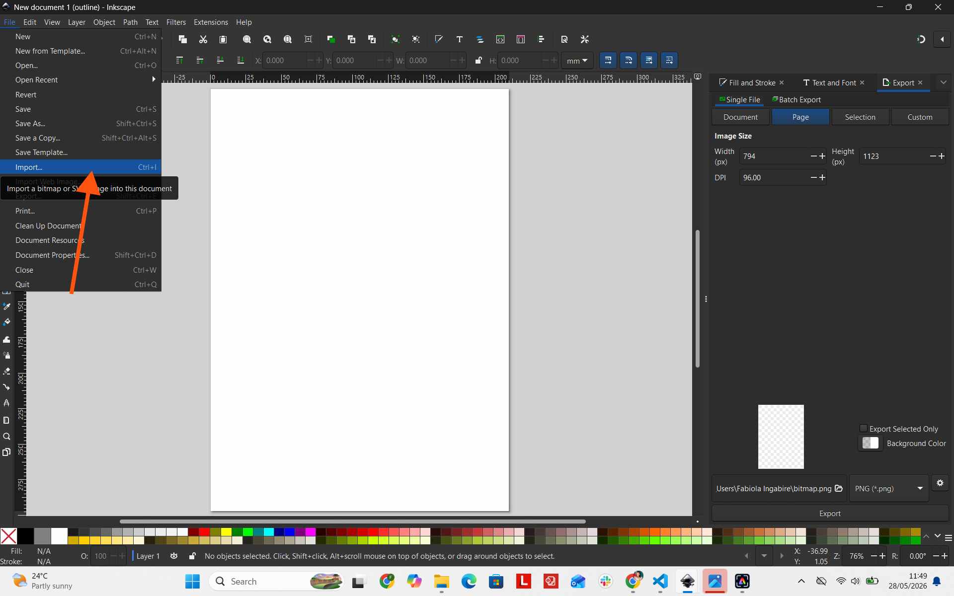
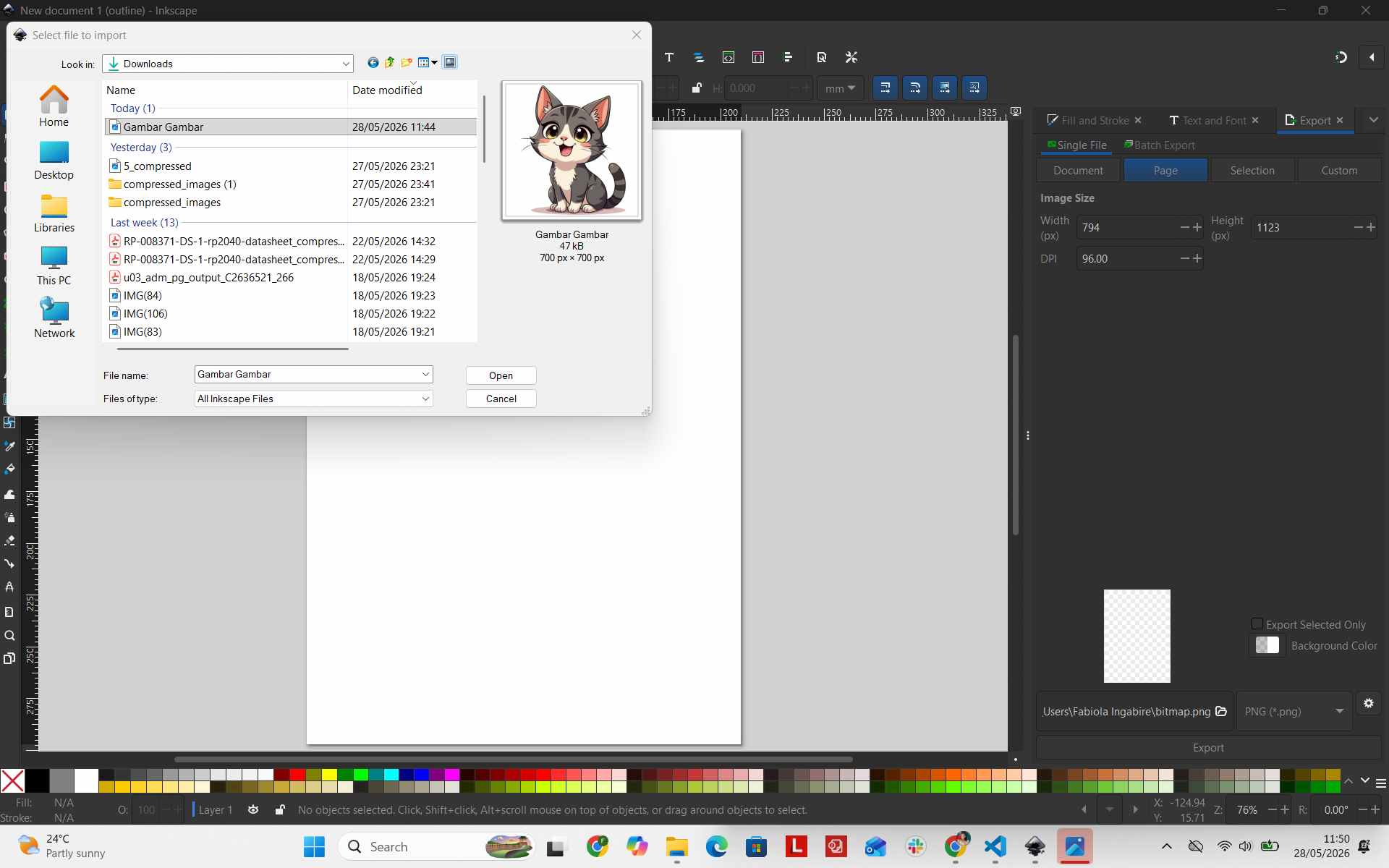
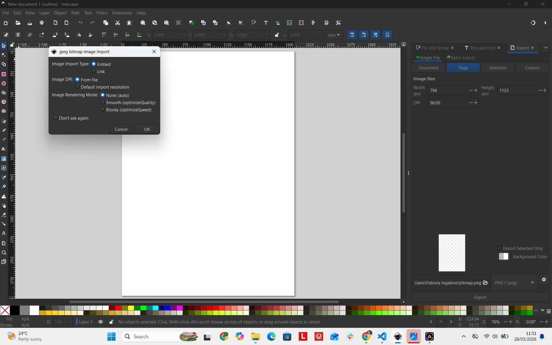
I imported the downloaded image into Inkscape to test vector trace features.
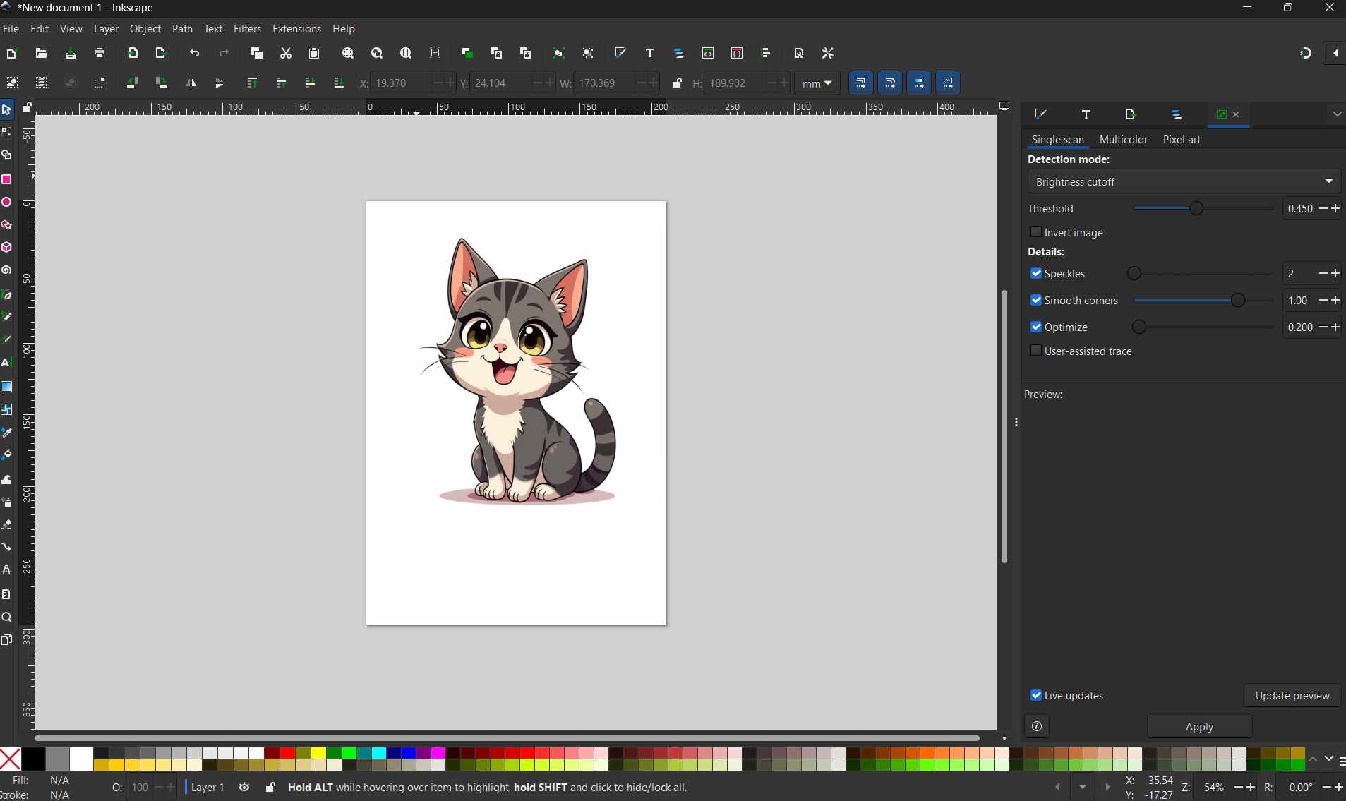
From there, I tested different trace features. First, I used Single scan:
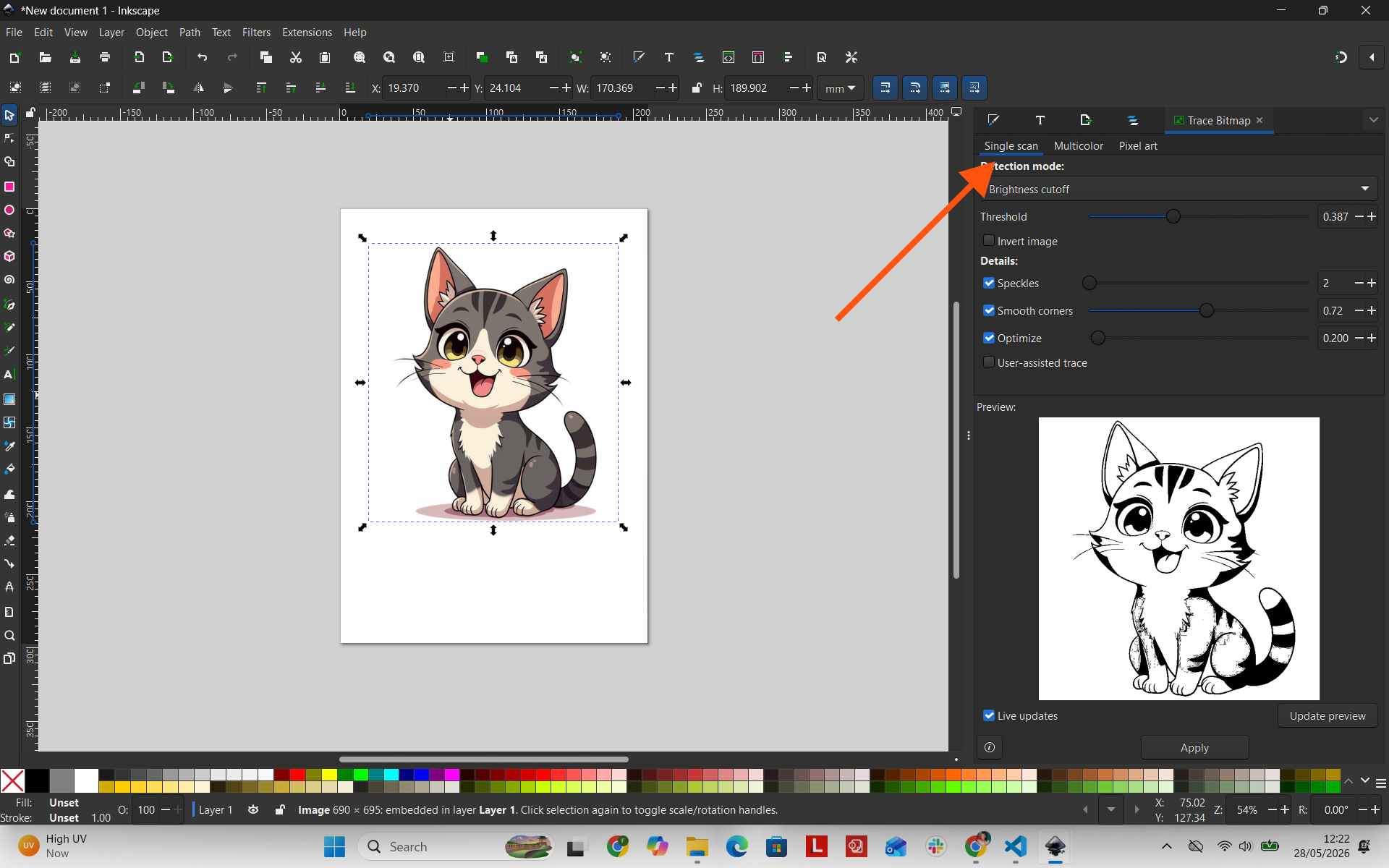
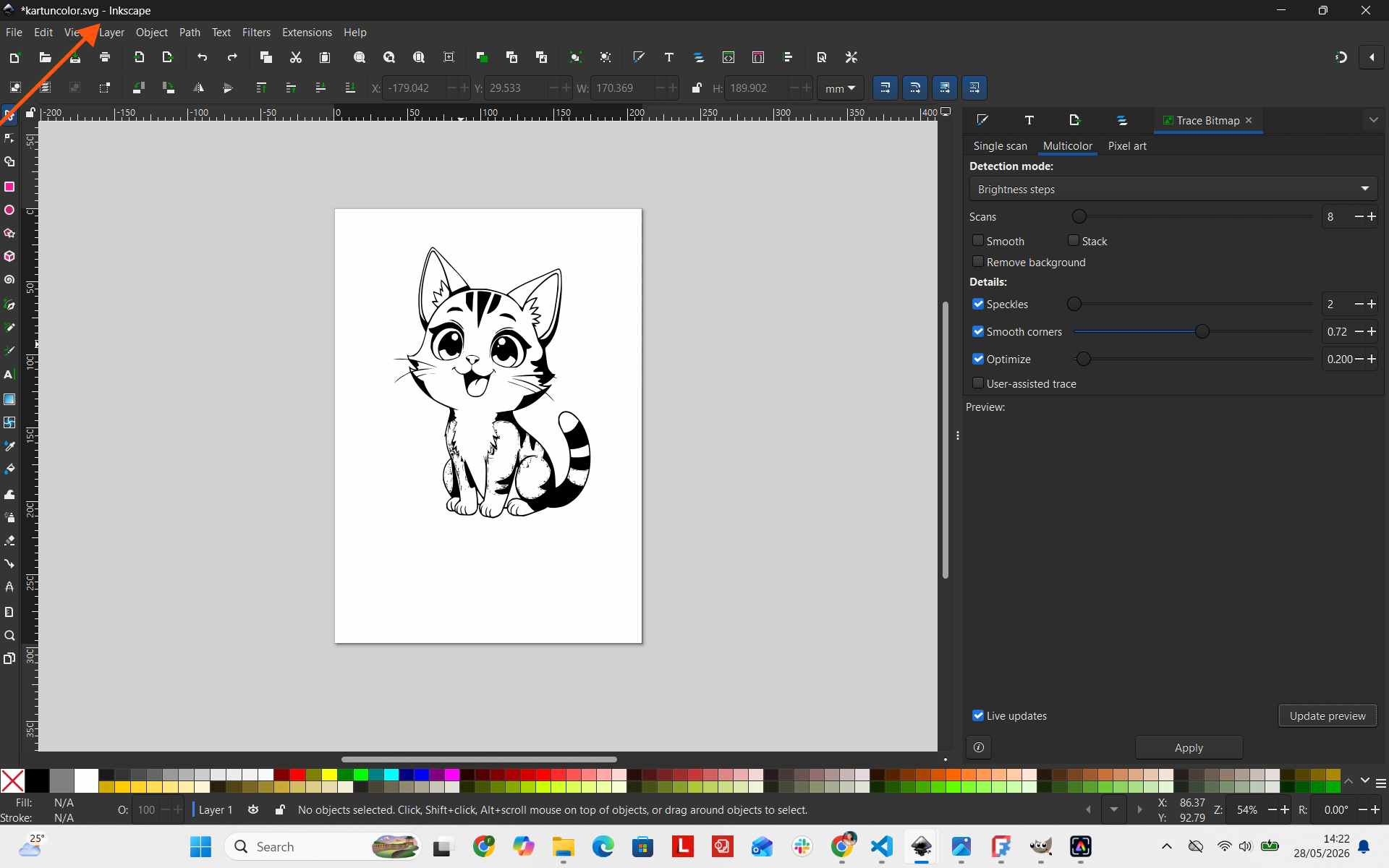
Next, I changed to Multicolor scan:
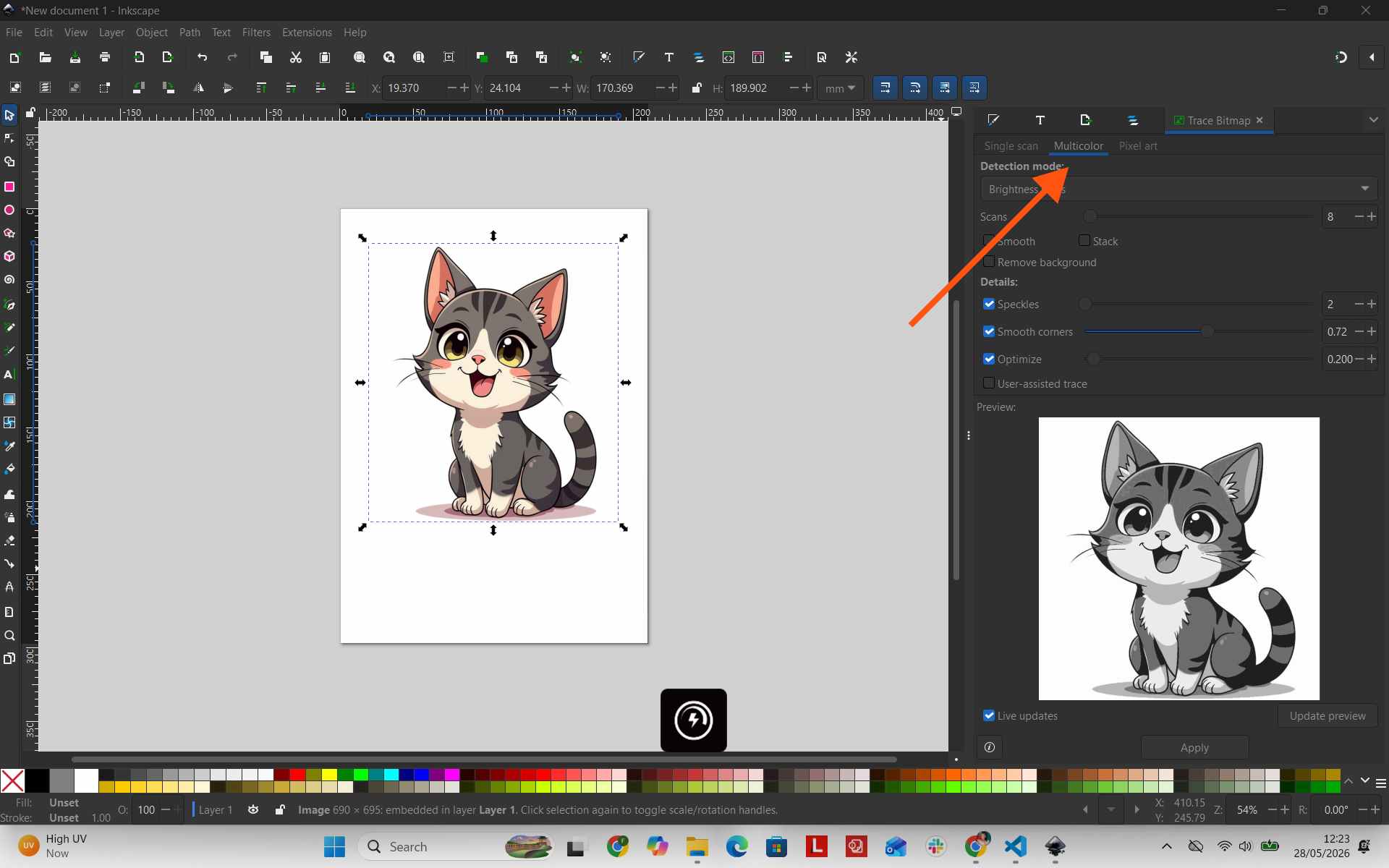
Then I tested Pixel art mode:
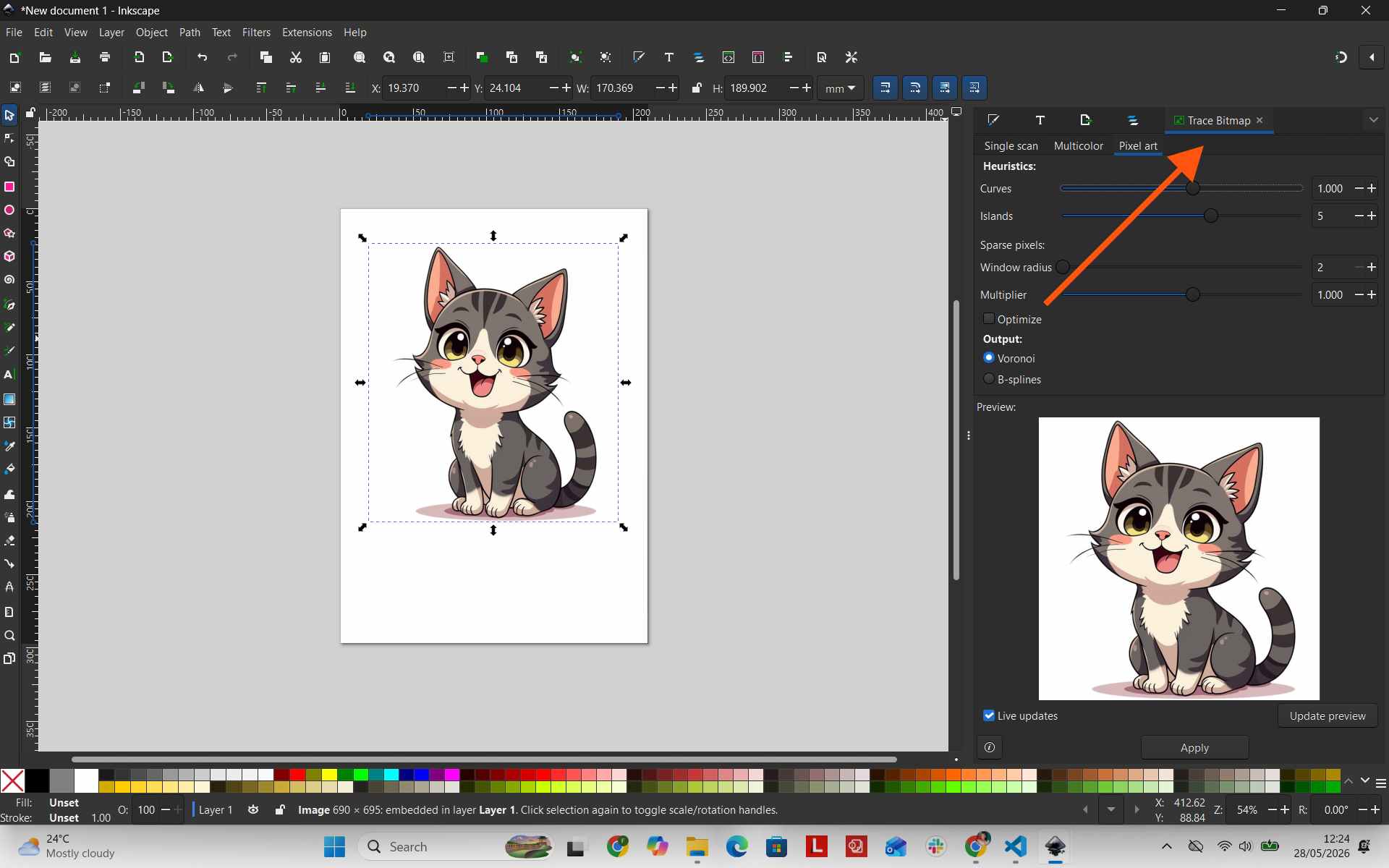
Because I wanted a clean vector format, I selected the Single scan output for the final composite vector graphic.
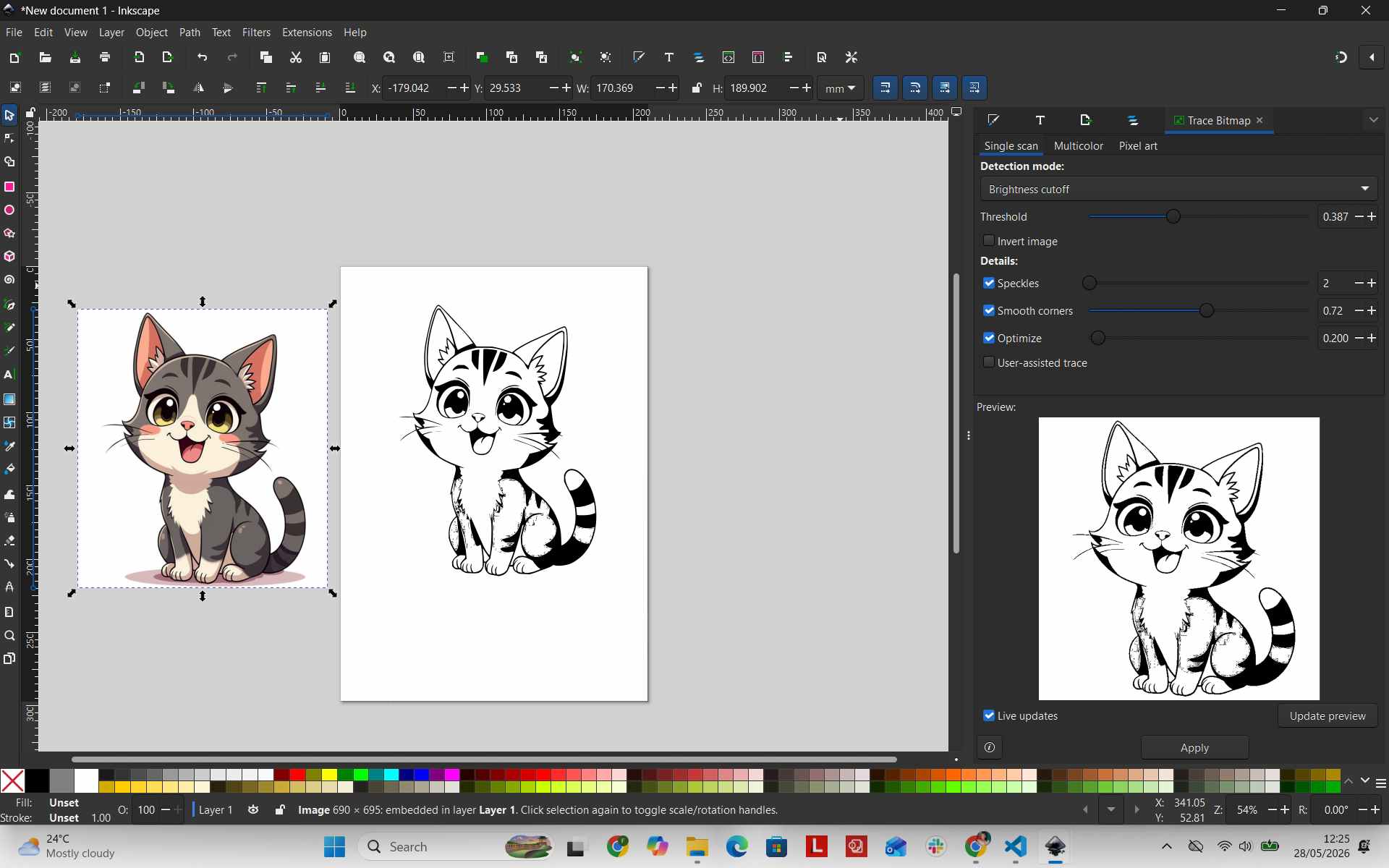
The resulting image is in SVG file format, which is the standard format for scalable vector graphics.
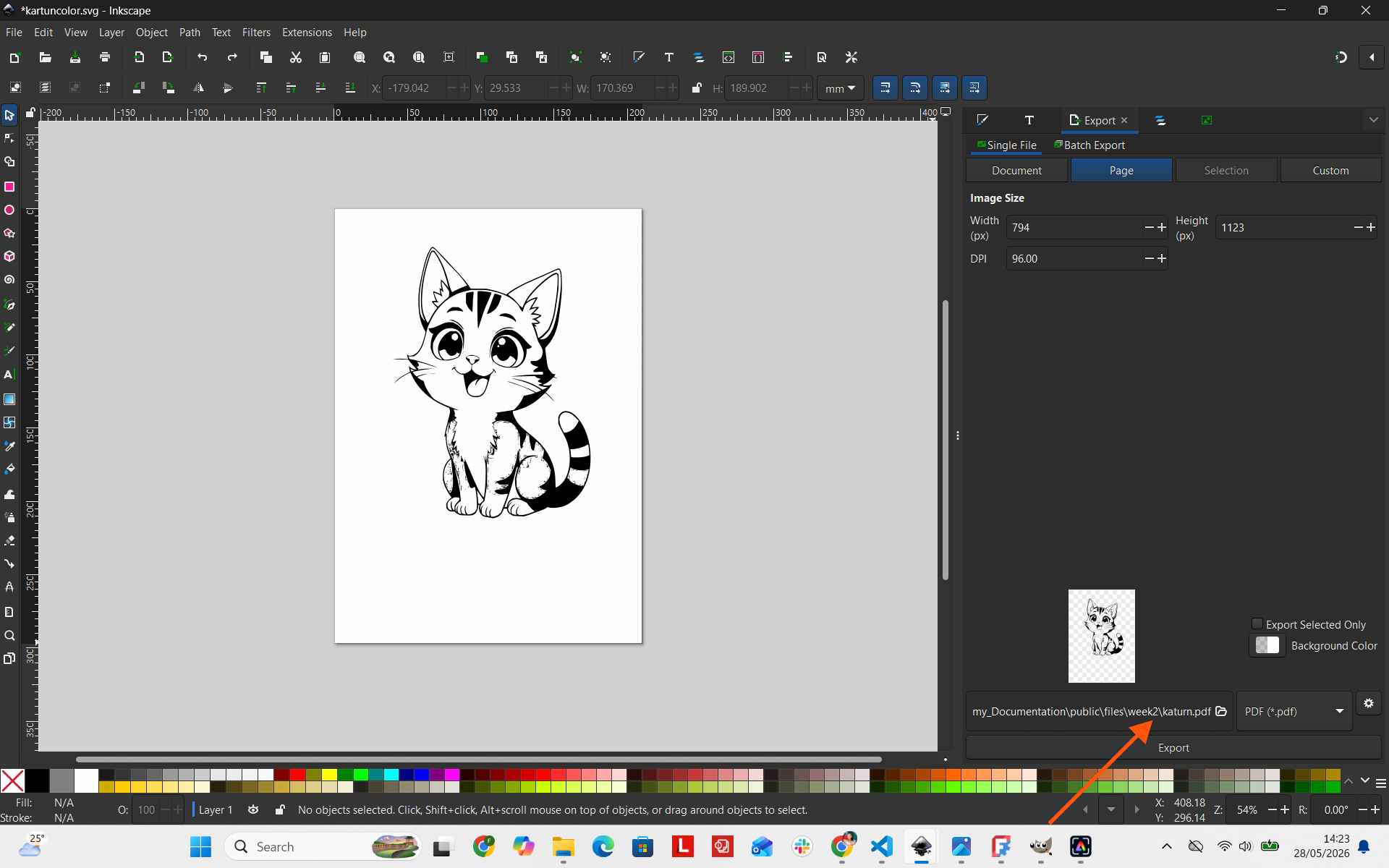
For documentation purposes, I also exported the graphic as a PDF for easy access.
Raster Image Creation With GIMP
Installation and Setup of GIMP
To create and process raster images, I used GIMP. Since GIMP was not pre-installed on my PC, I downloaded it from the official site.
Download GIMP
Official download link: Download GIMP
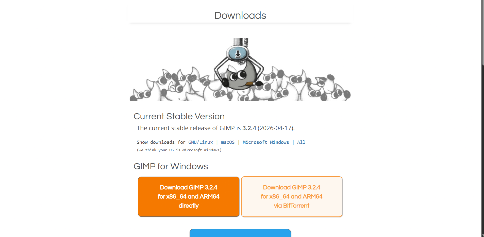
I selected the Windows OS installer and completed the download.
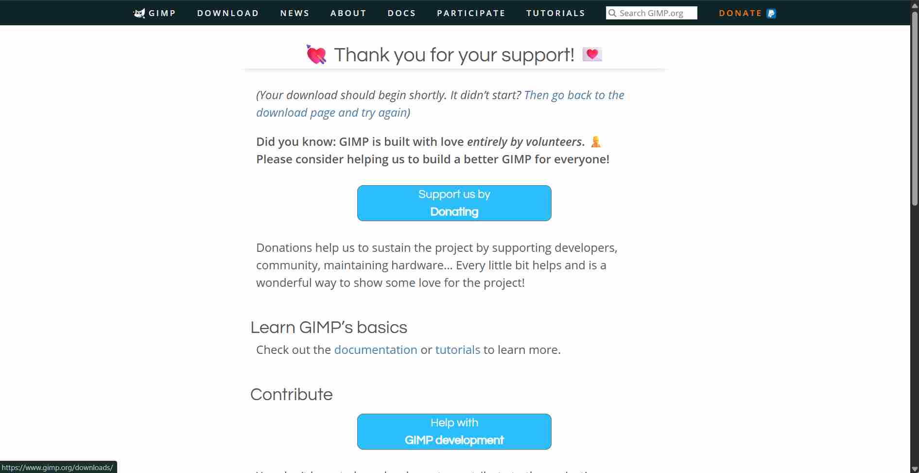
I ran the installer setup, accepted the licensing terms, and executed the installation process.
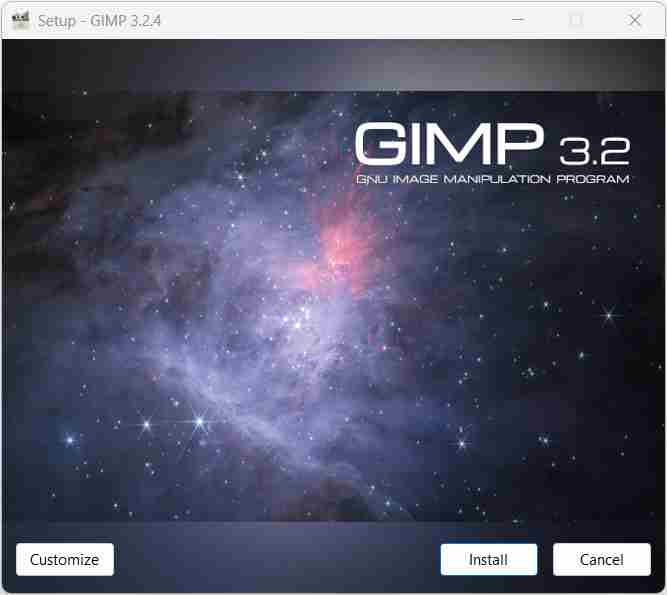
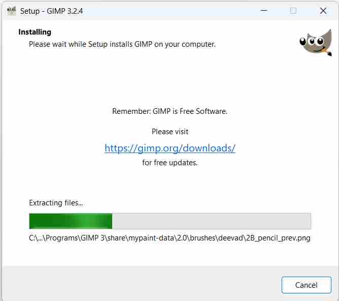
After clicking Finish, I launched GIMP to process raster media files.
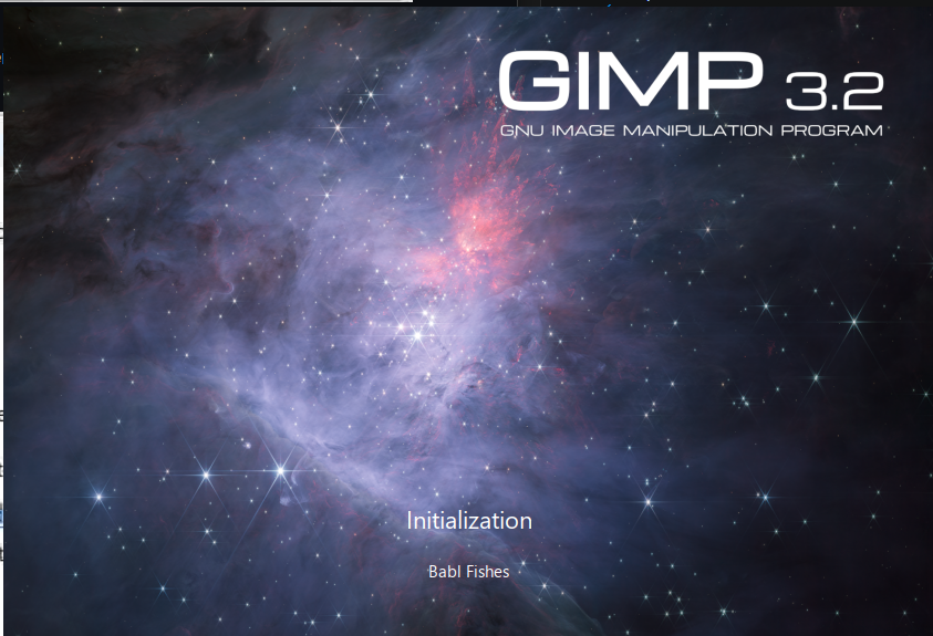
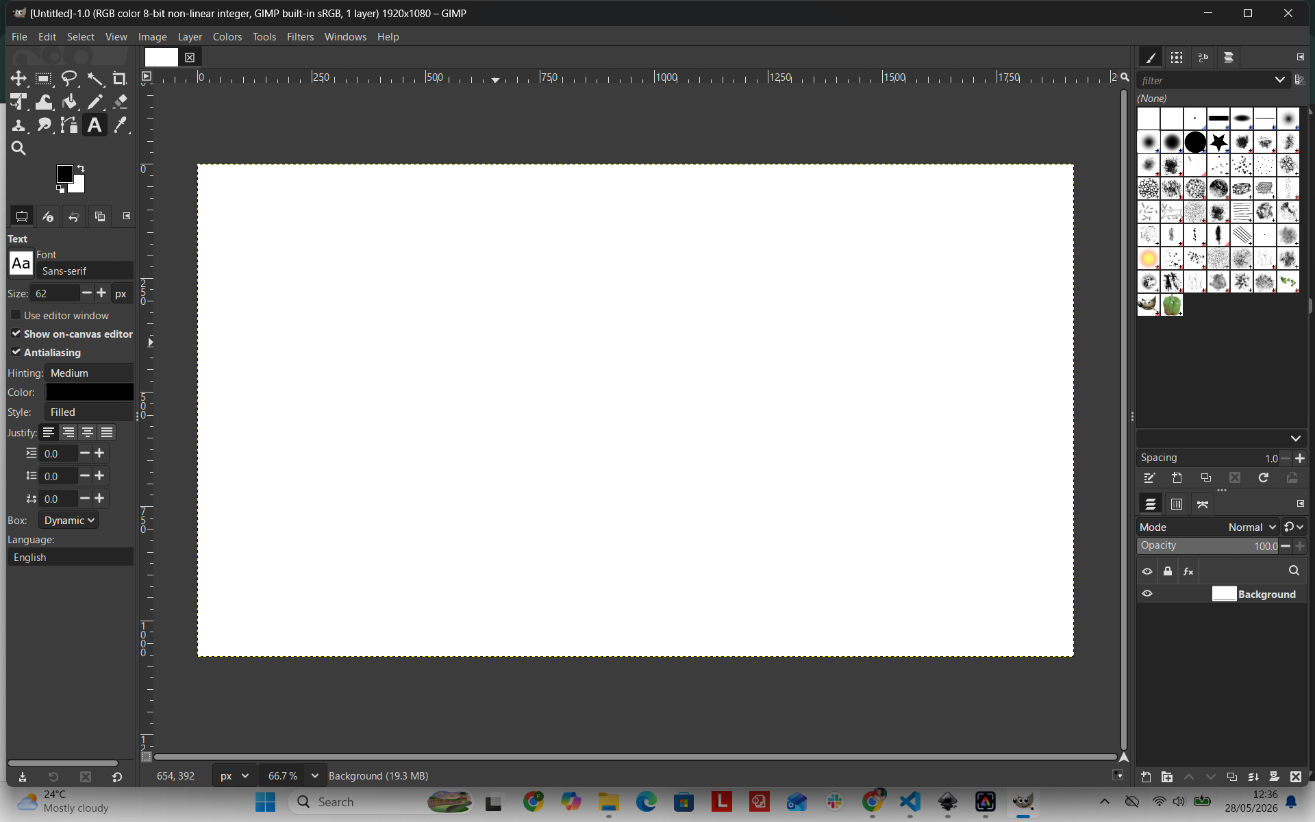
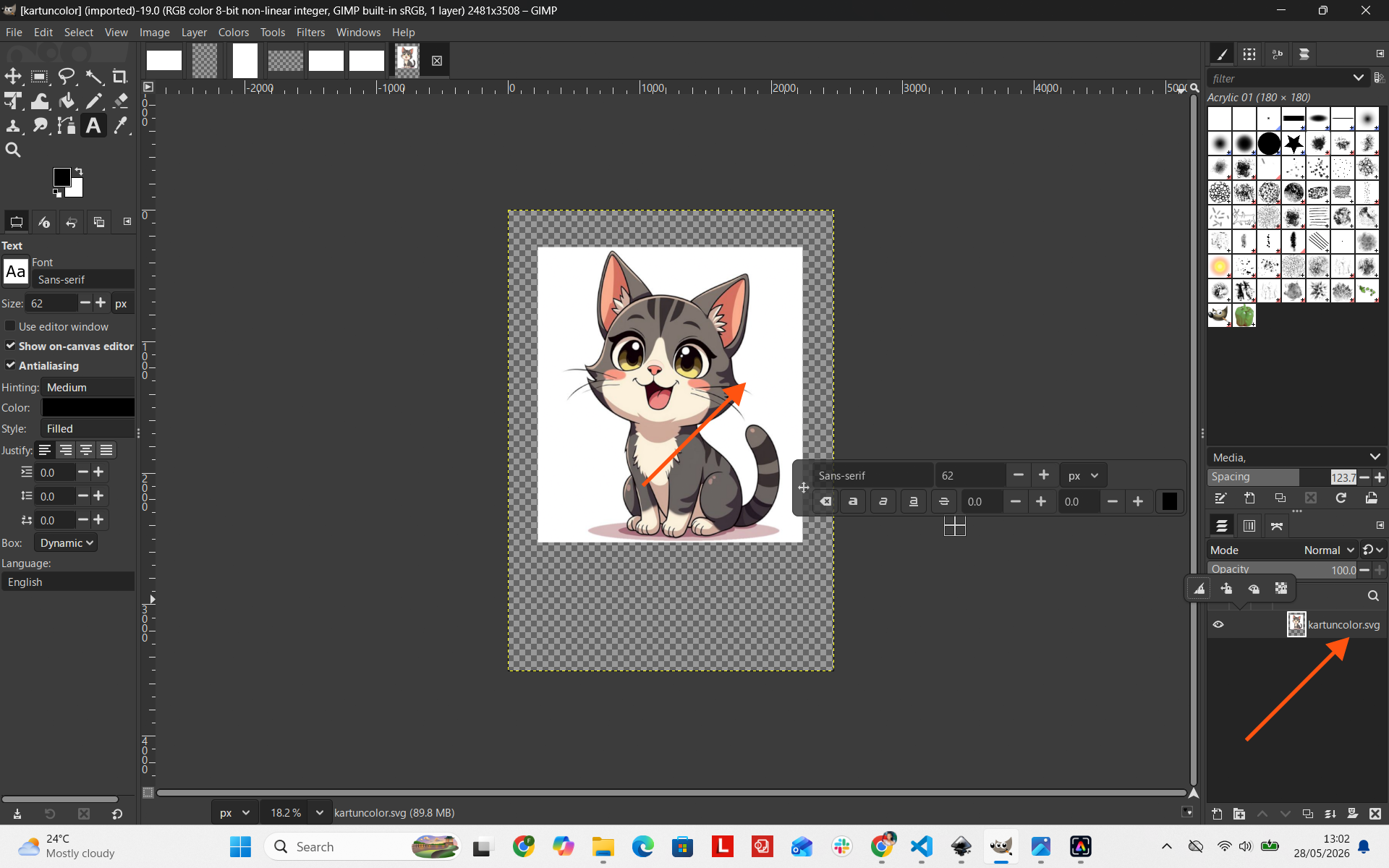
I imported the image asset into GIMP to perform raster operations.
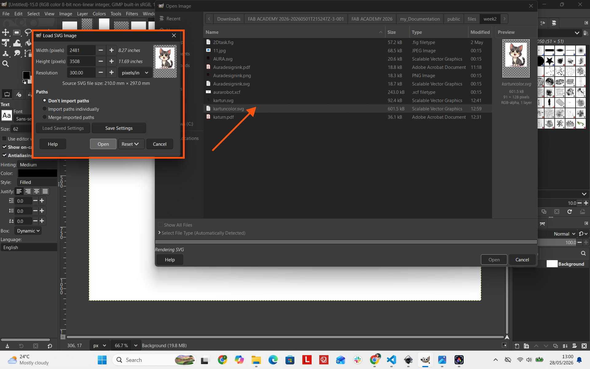
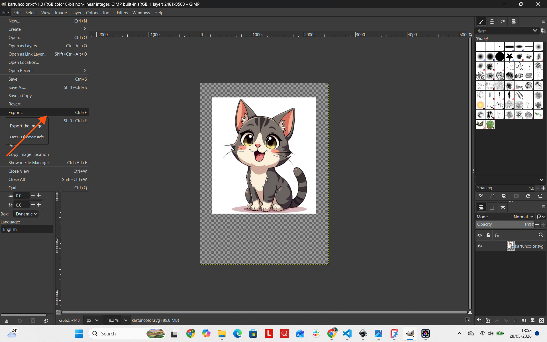
To export the final raster image, I clicked File → Export As and selected the PNG format.
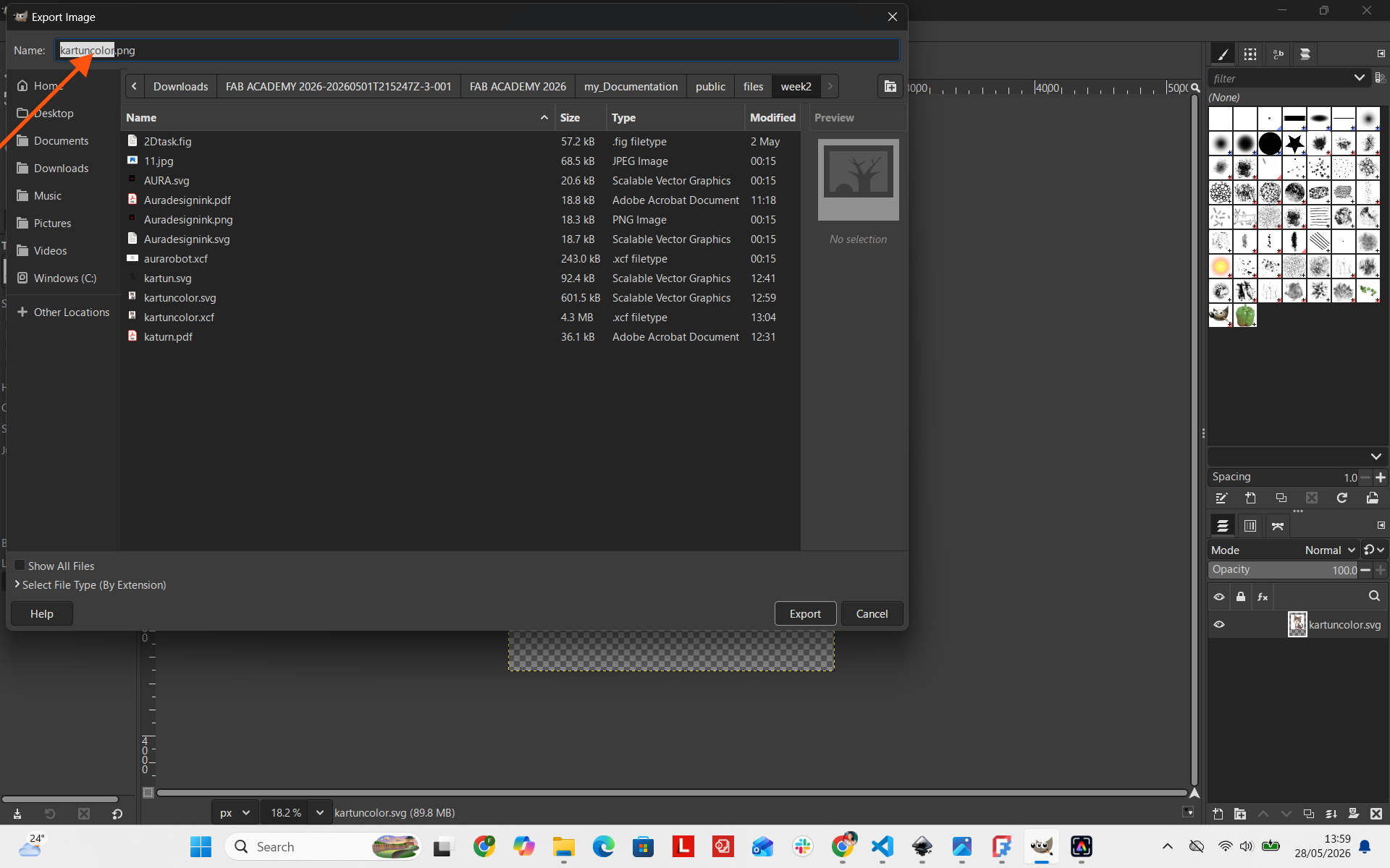
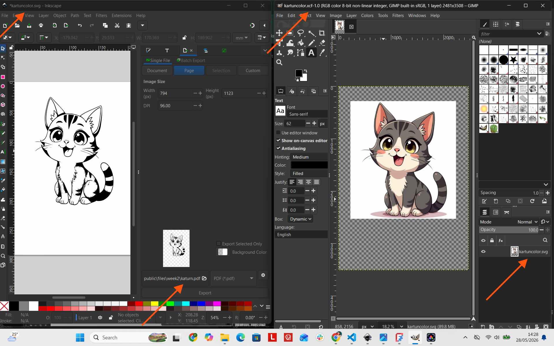
Raster vs Vector Design Comparison
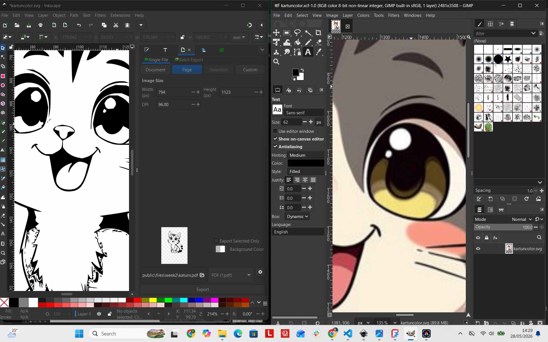
Raster images are composed of a grid of individual colored pixels, whereas vector graphics are defined mathematically through points, lines, curves, and geometric shapes.
Zooming into both formats highlights the fundamental resolution differences:
Modeling 3D design of My Final project Enclosure
To model 3D Design of my final project enclosure I used solidworks where I design two parts the Front body and Back body and add the section for the sensor exposition and other components.
Modeling the FrontBody
I started by creating a new part in SolidWorks and selecting the Front Plane to begin the sketch.I designed the rectangle for the front body and Extruded Boss it to have a 3D shape. I also added the necessary features for the sensor exposition like the slot for the OLED Display and at the buttom I added the three slot for the button.
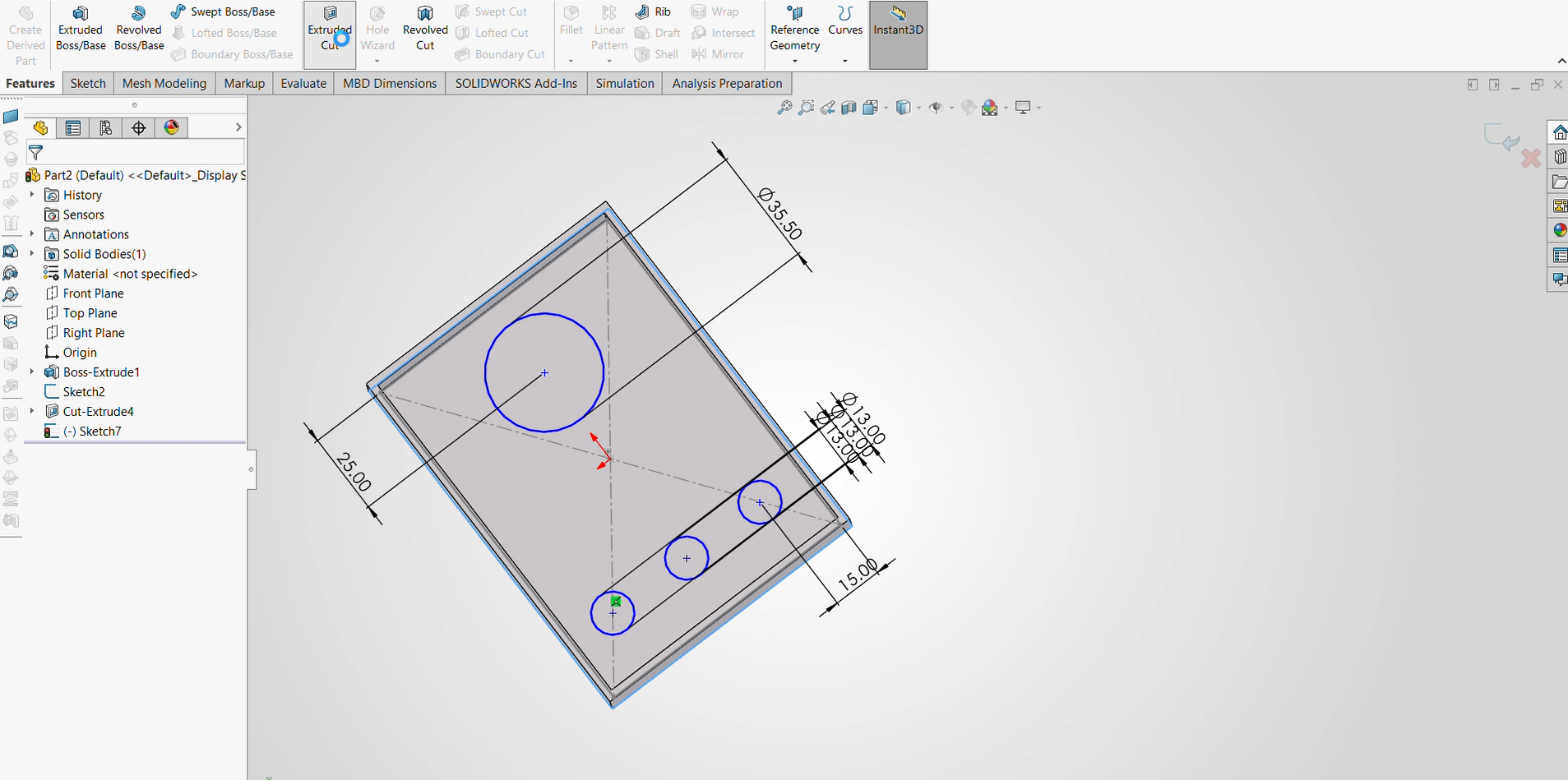
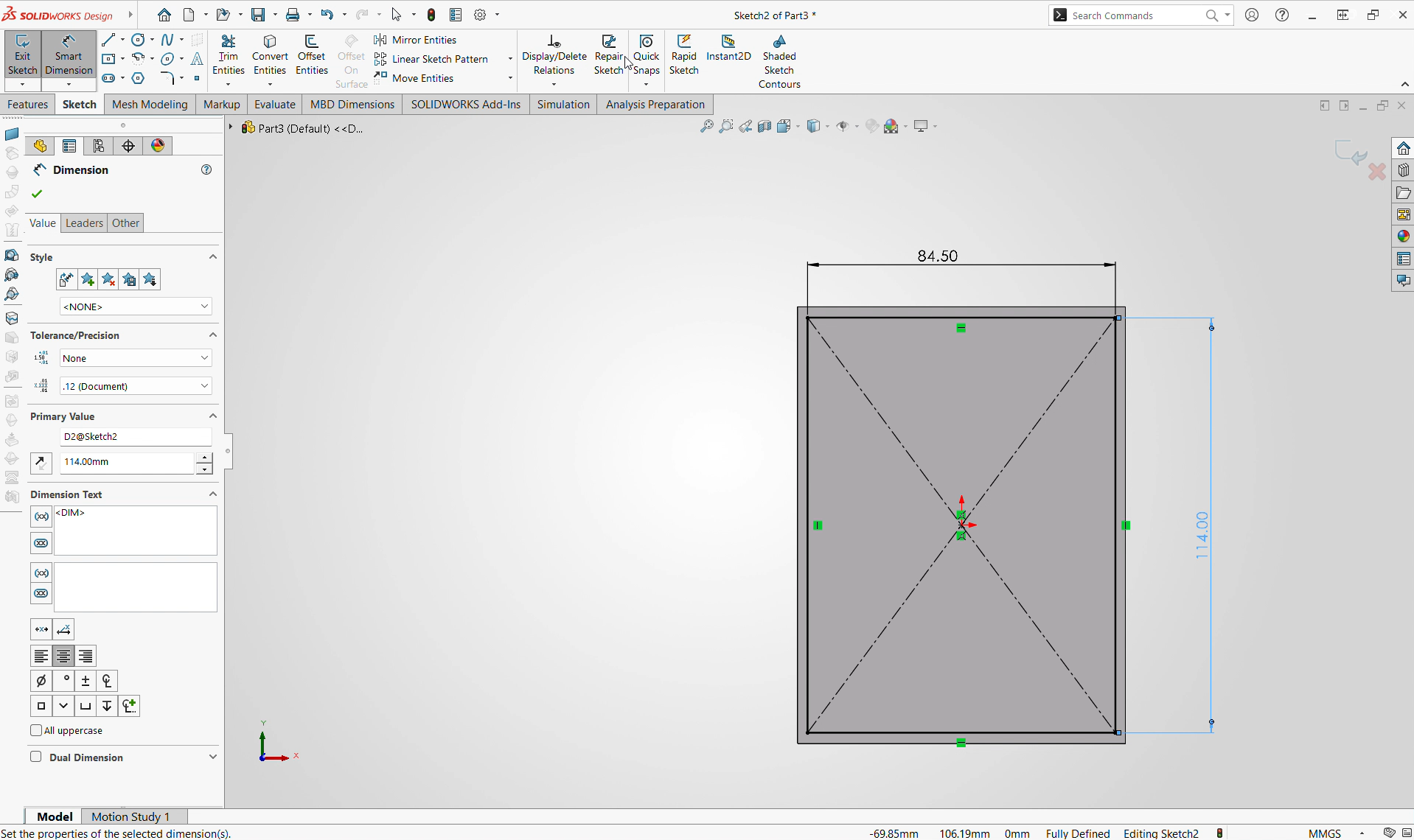
I added the necessary dimensions to the sketch to ensure that the design met the required specifications. I used the Smart Dimension tool to add dimensions to the sketch.
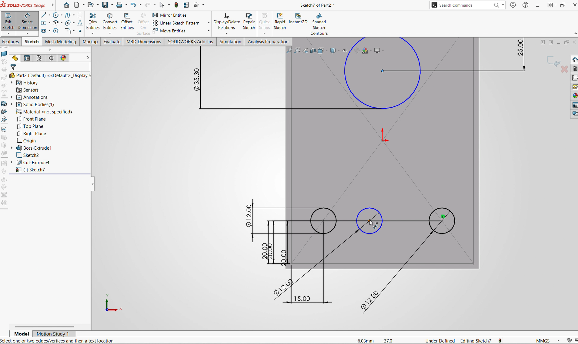
After completing the proper dimension I added the Extrude cut to create the slot for the OLED Display and the three slots for the buttons.
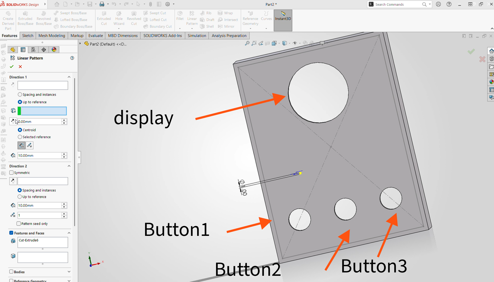
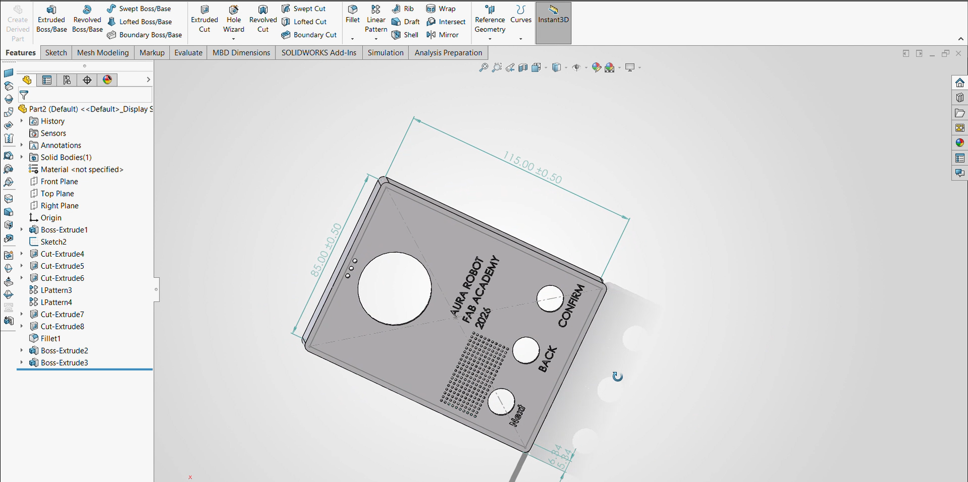
I created the slot for the speaker using linear pattern of small circle I cut and also added fillets to the edges of the front body to improve the aesthetics and ergonomics of the design.
Modeling the BackBody
I created a new part in solidworks and selected the Front Plane to begin the sketch. I designed the rectangle for the back body and add the dimensions to make the shape fully defined .
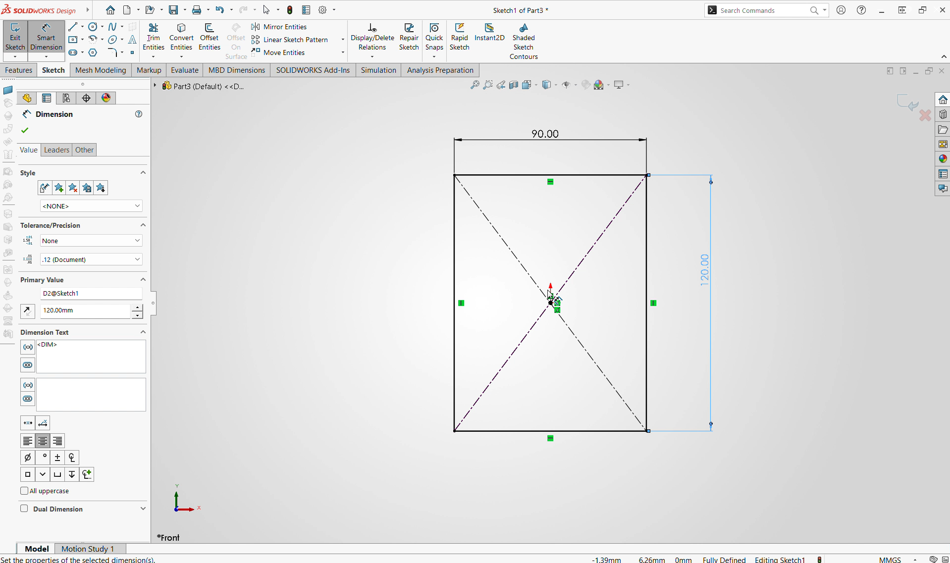
I added the Extrude Boss to create the 3D shape of the back body.
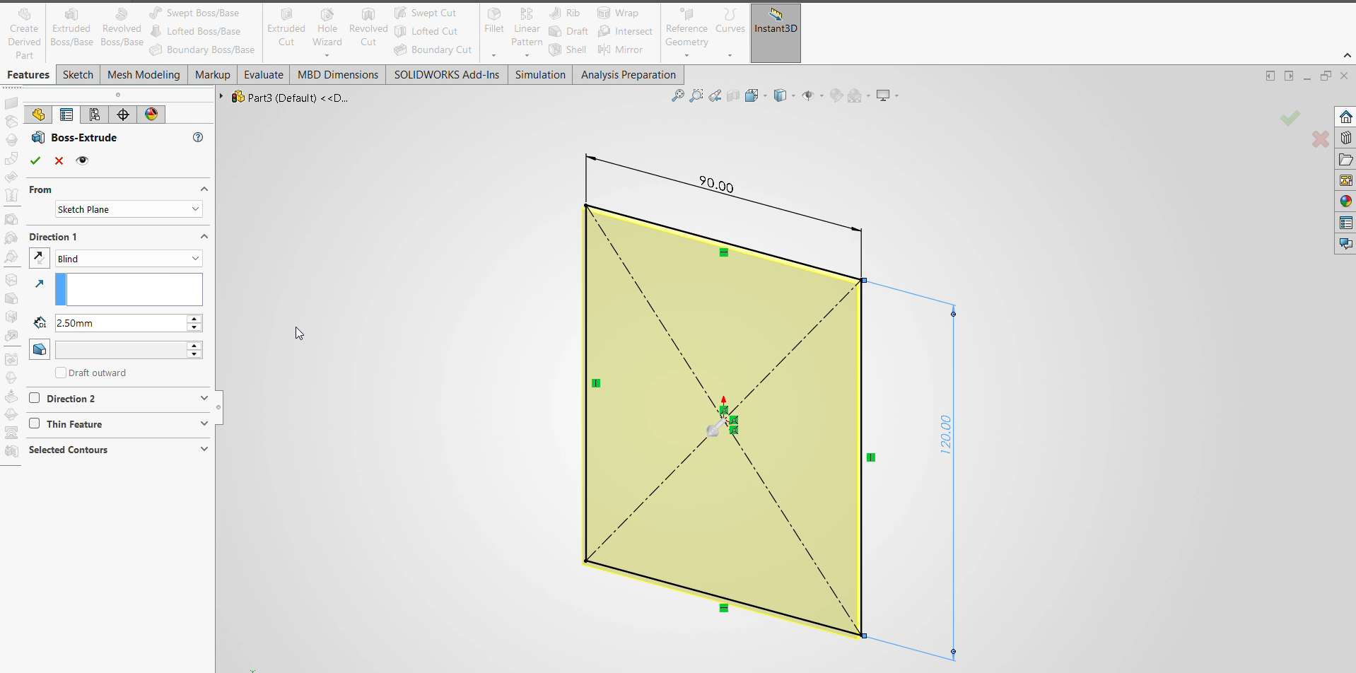
After having the base design I added second rectangle to make good and strong fitting for on the front body.
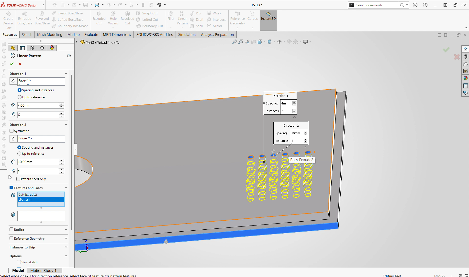
I also used linear pattern to add the small circles for the opening of the wifi and other internal components .
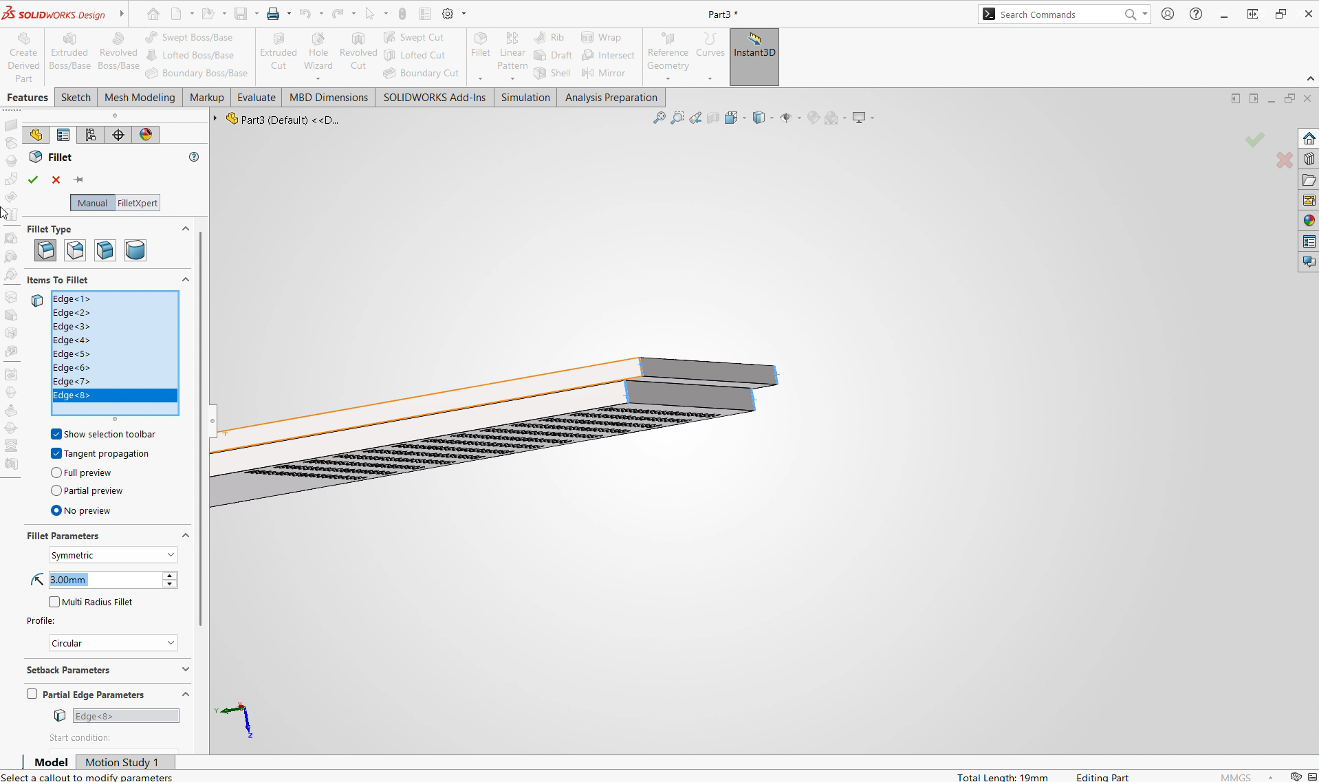
I added the fillet to the edges of the back body to improve the aesthetics and ergonomics of the design.
Assembling of Front Body and Backbody
After completing the design of the front and back bodies, I created a new assembly in SolidWorks and inserted both parts into the assembly. I used the Mate feature to align and position the parts correctly. I added the necessary mates to ensure that the parts were properly aligned and constrained.
3D Modeling Using SolidWorks and FreeCAD
Choosing SolidWorks and FreeCAD allows for complete exploration of parametric mechanical engineering across both industry-standard commercial tools and open-source platforms.
Modeling a Phone Stand in SolidWorks
I designed a phone stand to practice parametric 3D modeling for electronic enclosures and functional desktop accessories. This accessory serves as a companion dock for viewing notifications and interacting with the smart clock interface hands-free.
I selected the Front Plane to start the base sketch.
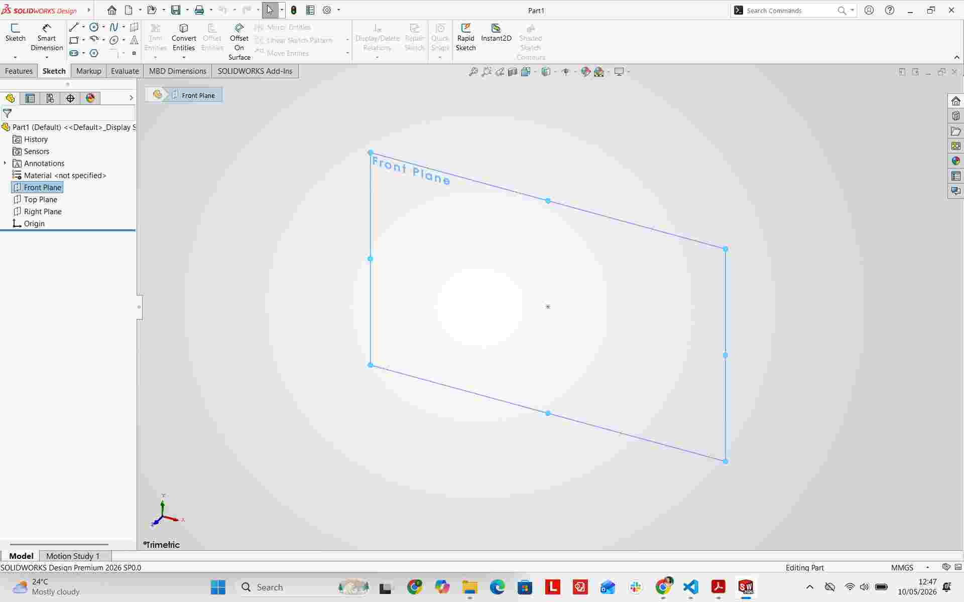
Using the Line tool, I sketched the profile outline of the stand.
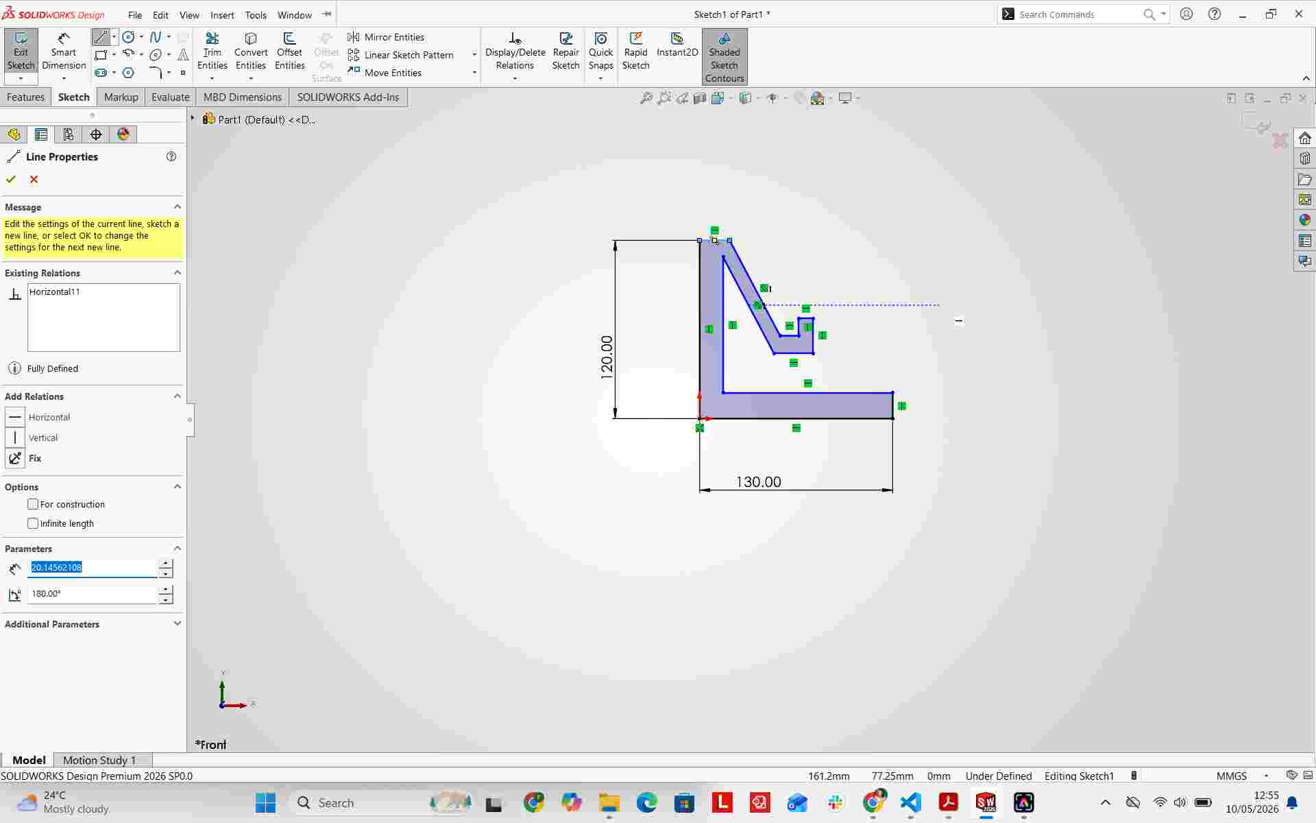
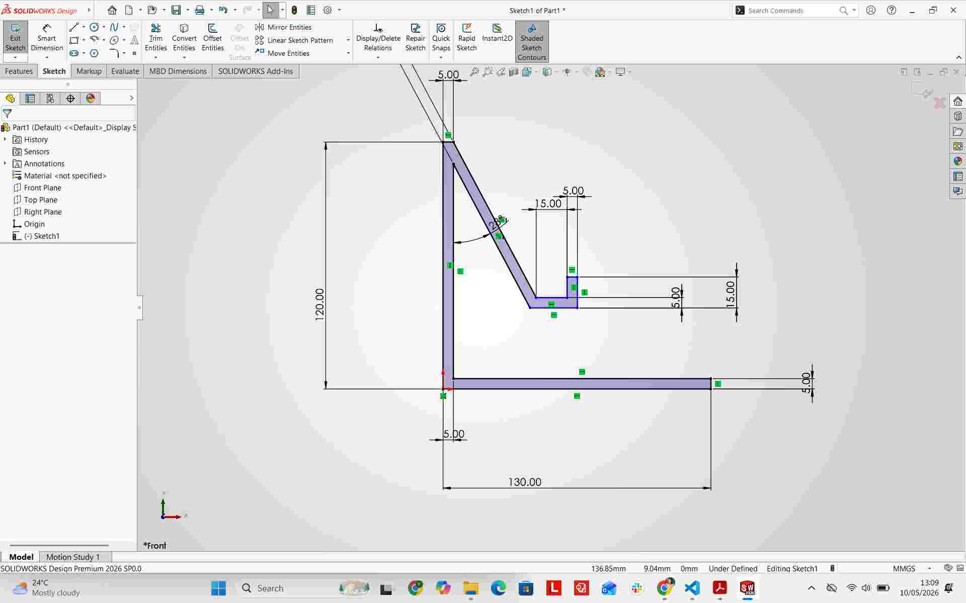
I added Smart Dimensions to fully constrain the sketch geometry.

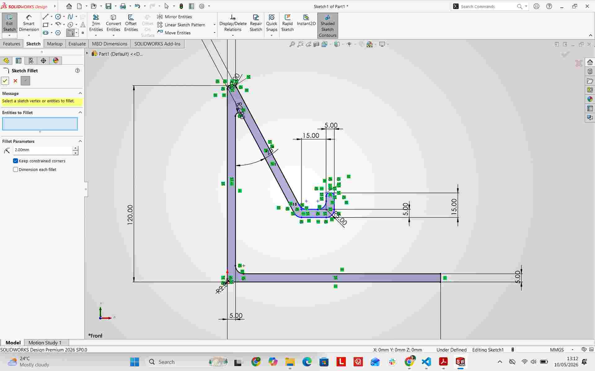
I applied Sketch Fillets to sharp corners to improve ergonomics and aesthetics.
Using the Boss Extrude feature, I extruded the base profile to a width of 80mm.
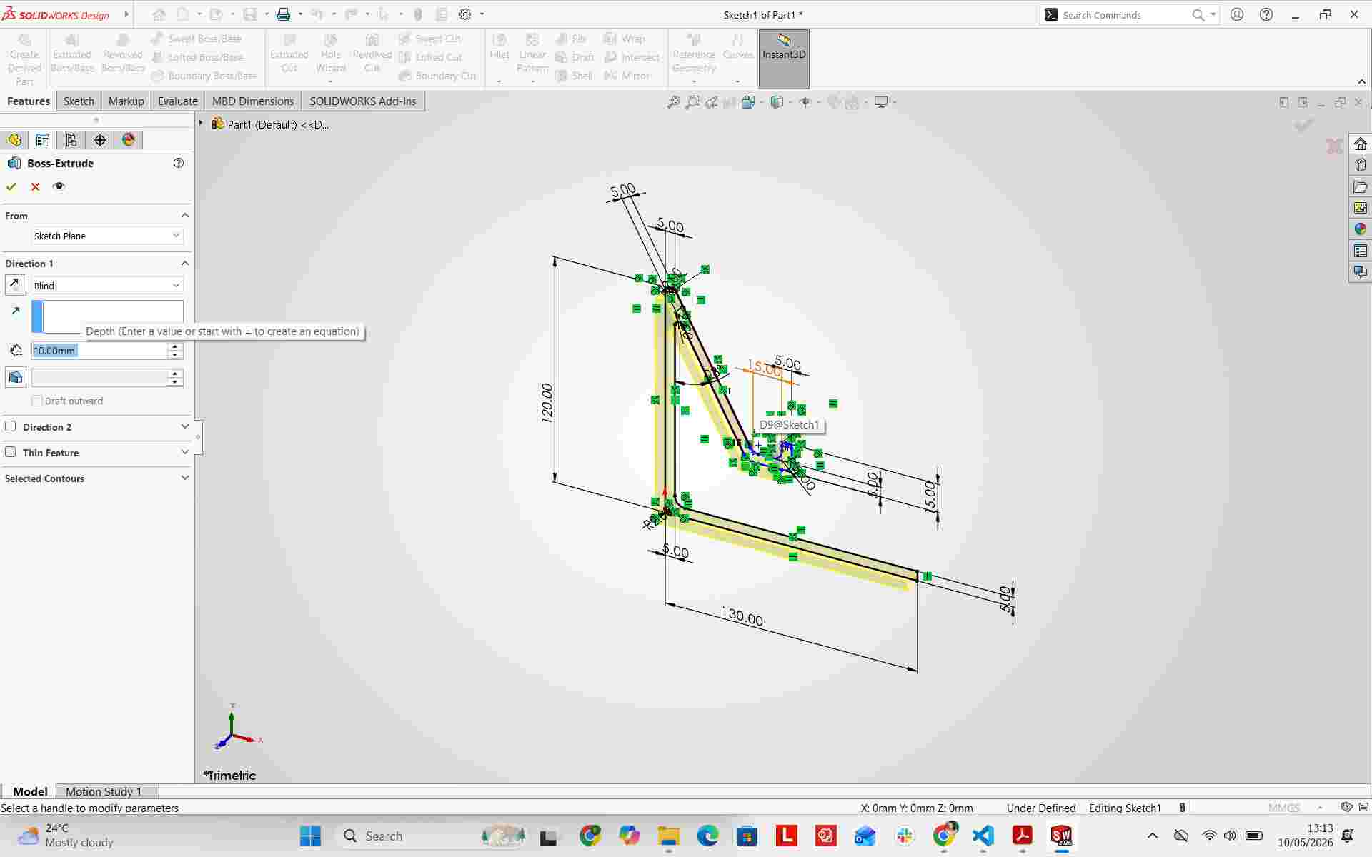
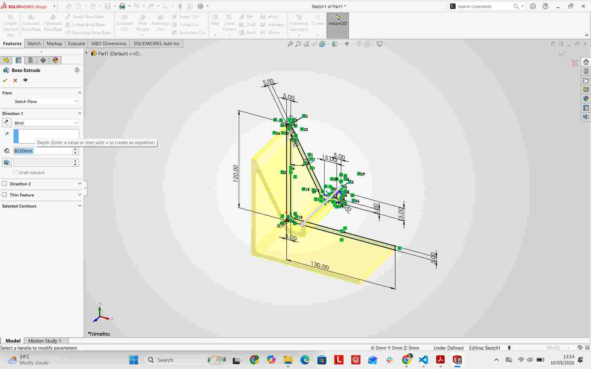
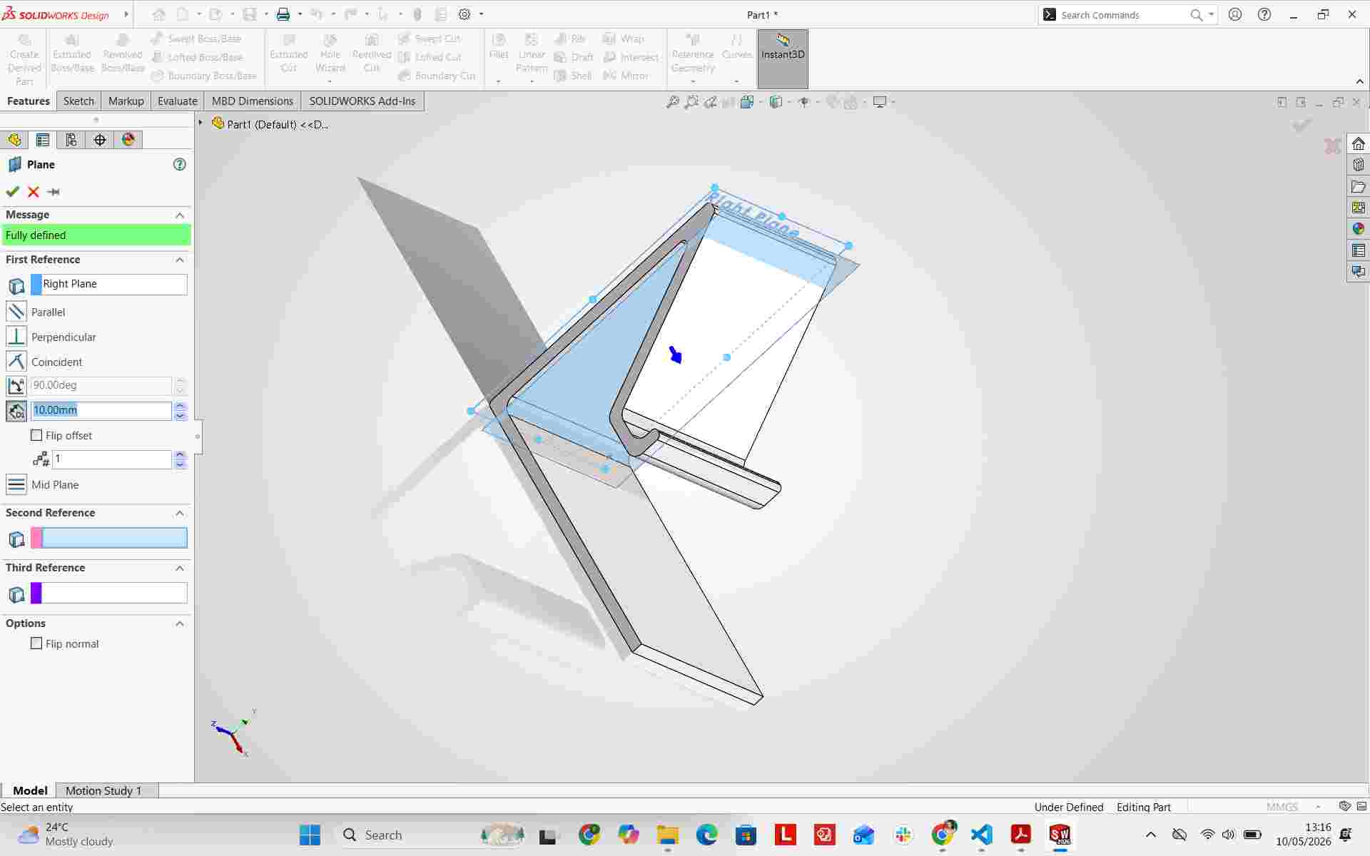
I switched to the Right Plane to create an additional cable pass-through feature.
I sketched a slot cutout profile for charging cable routing.
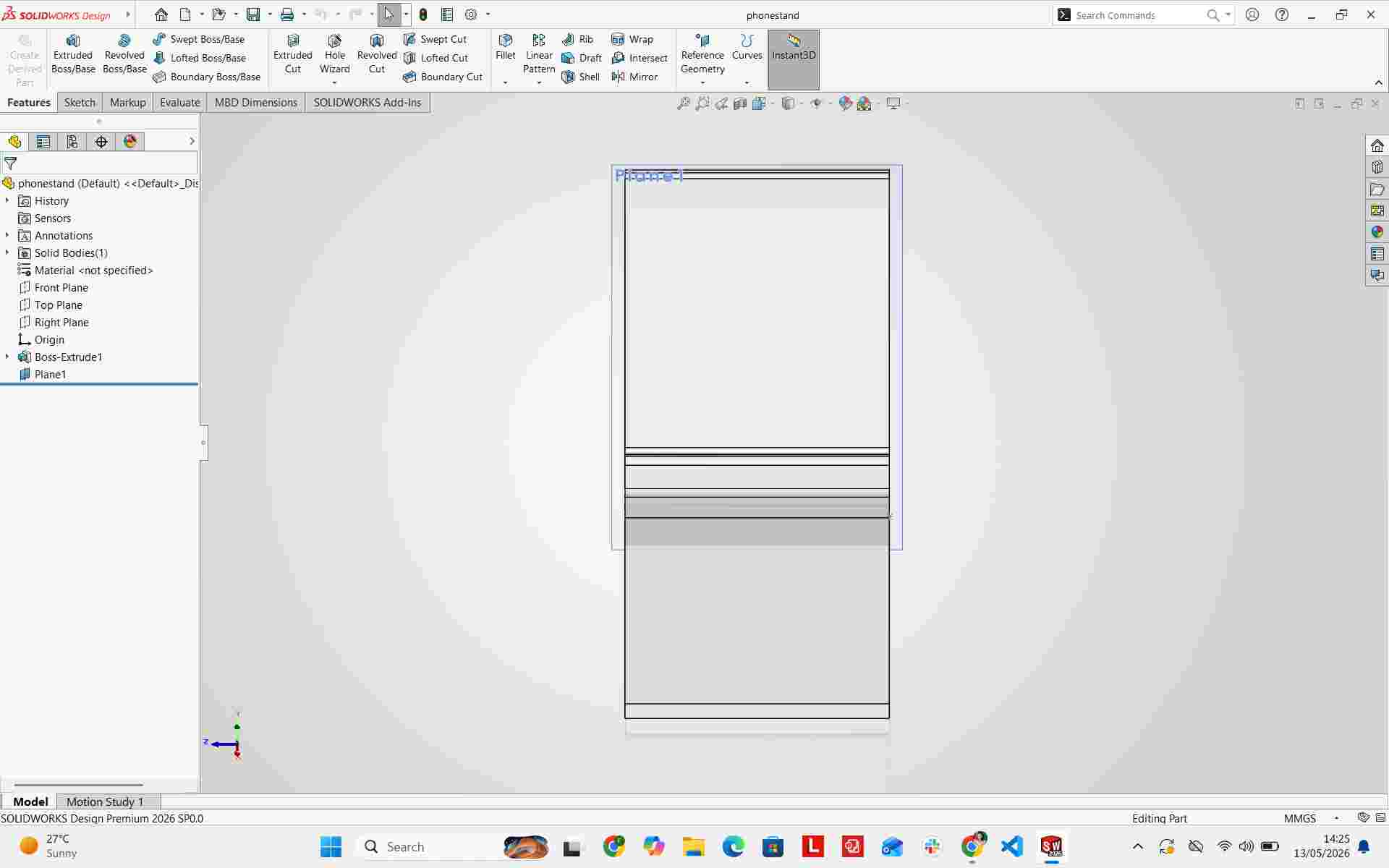
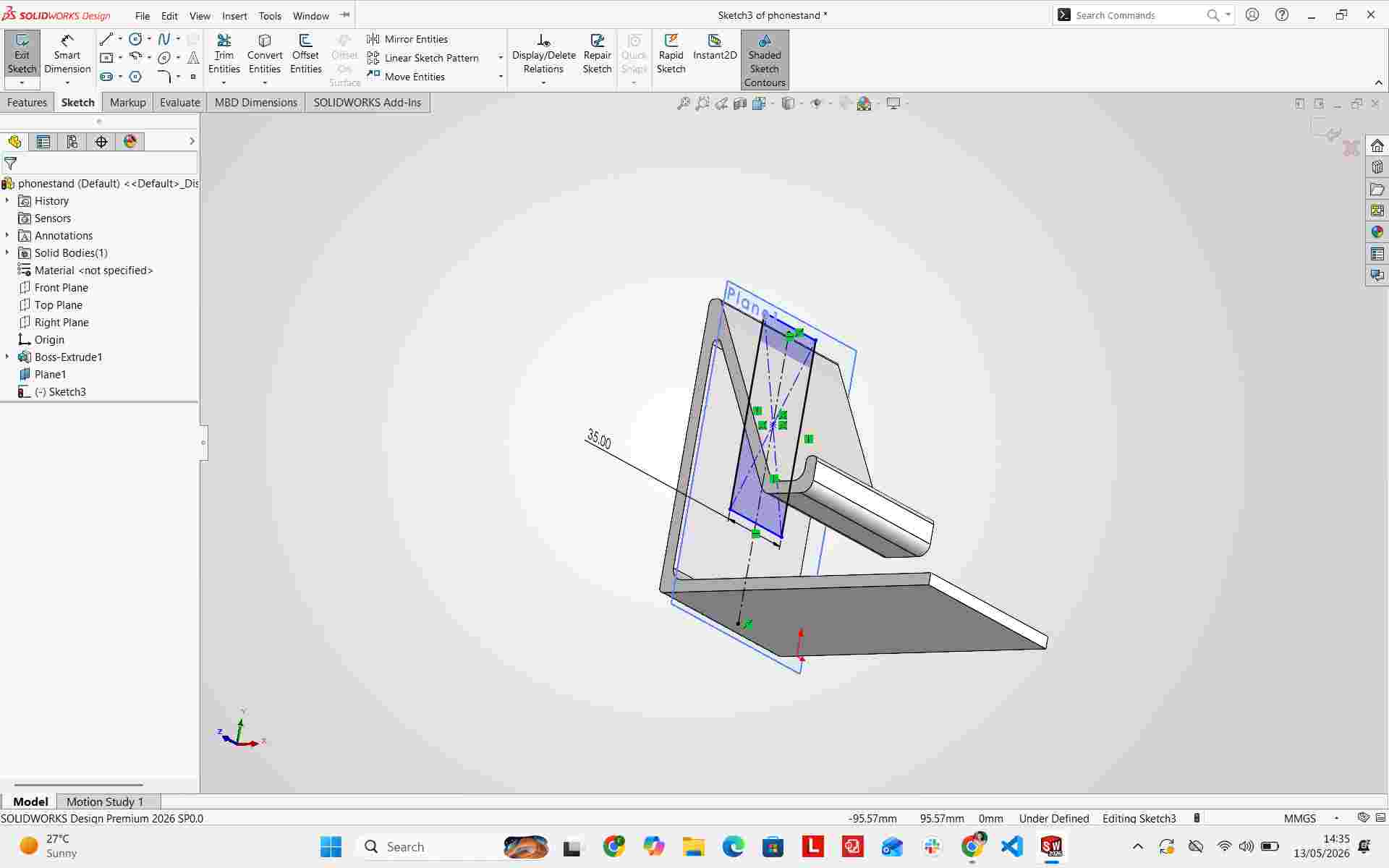
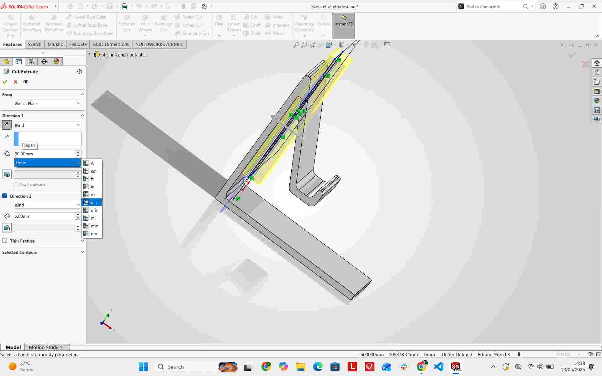
Using Extruded Cut, I removed material through the body to create the port opening.
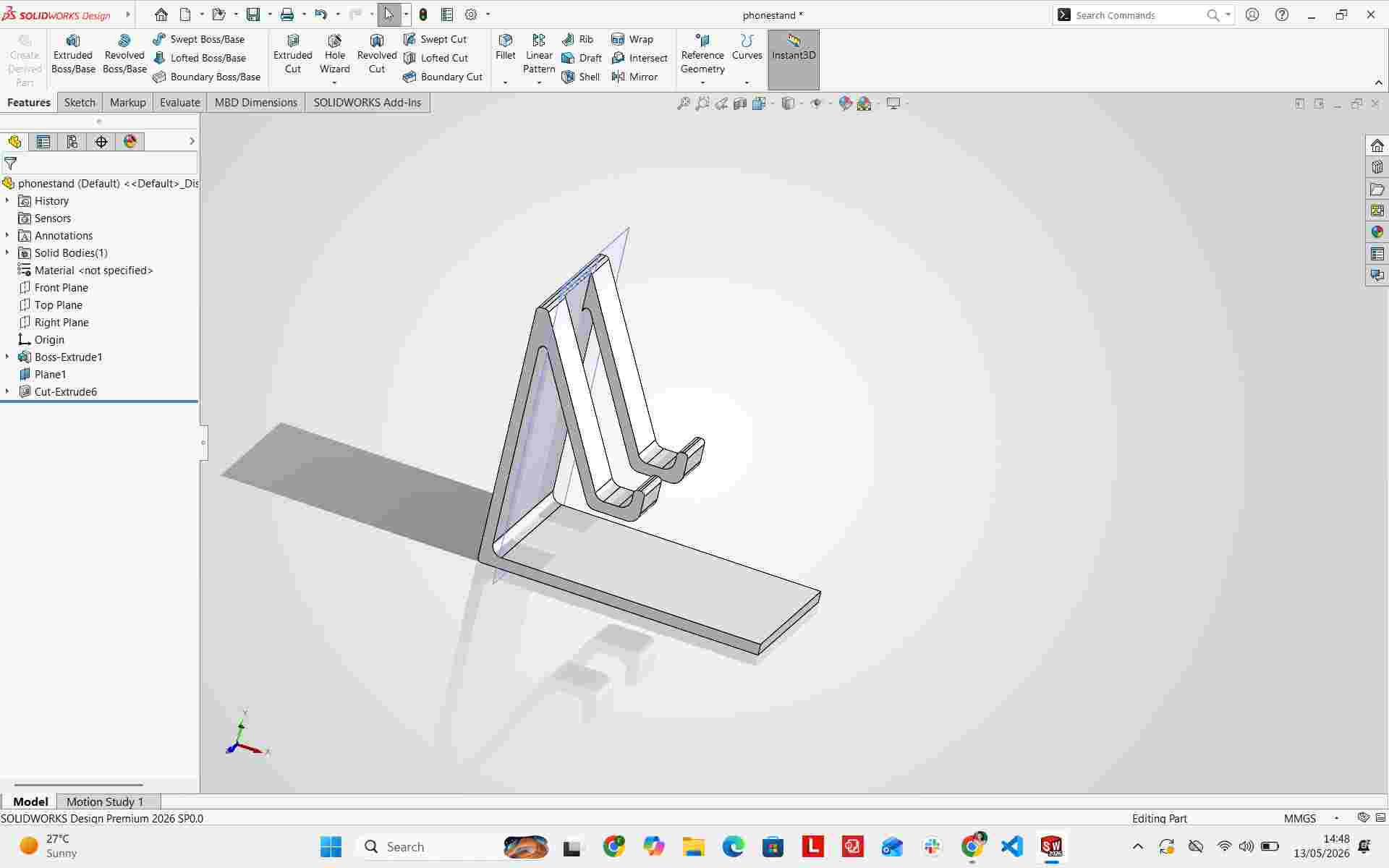
Here is the completed solid model after performing extrusions, fillets, and cutouts.
3D Design of AURA Enclosure Using FreeCAD
To explore open-source 3D CAD modeling, I used FreeCAD to convert the 2D AURA robot layout into a complete 3D parametric assembly.
Download and Install FreeCAD
I downloaded FreeCAD for Windows from the official site: Download FreeCAD
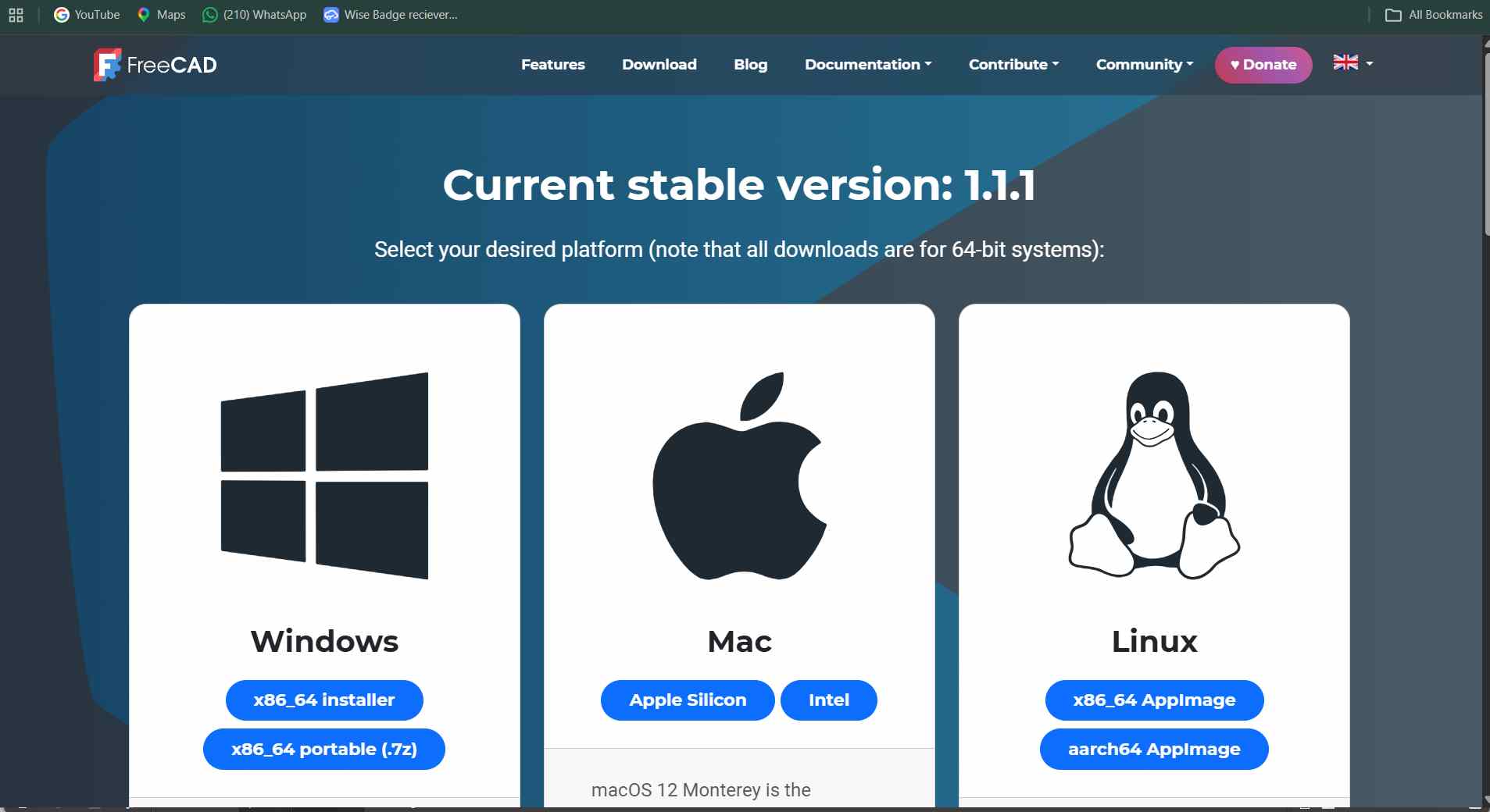
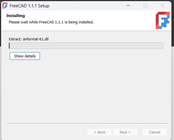
I executed the installer and completed the setup steps.
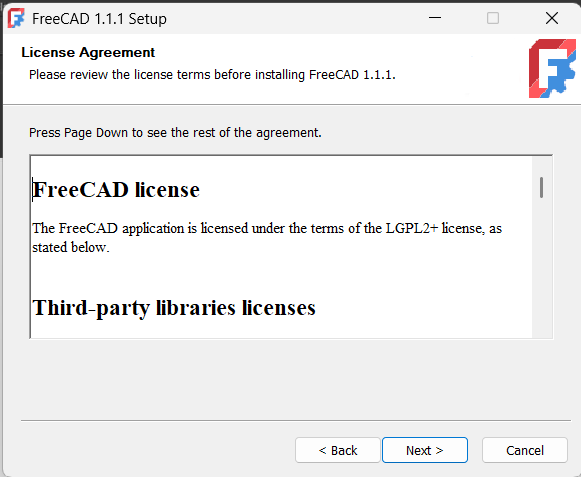
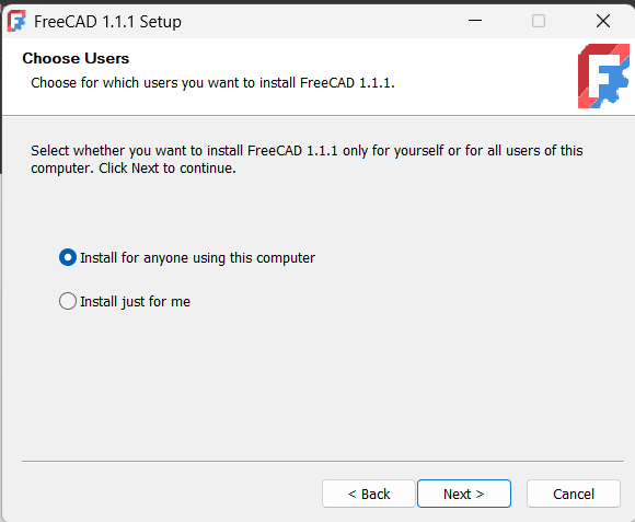
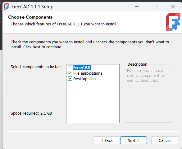
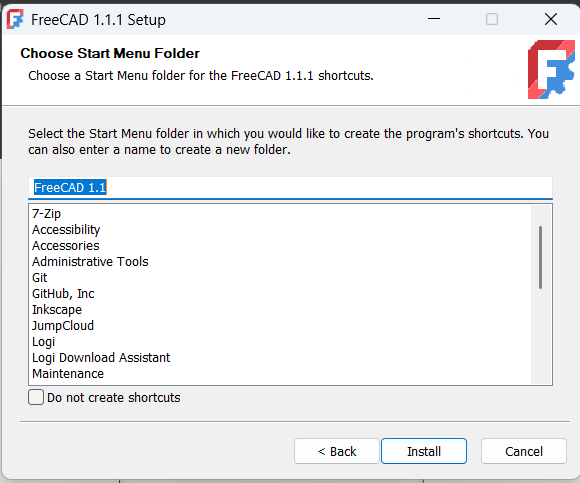
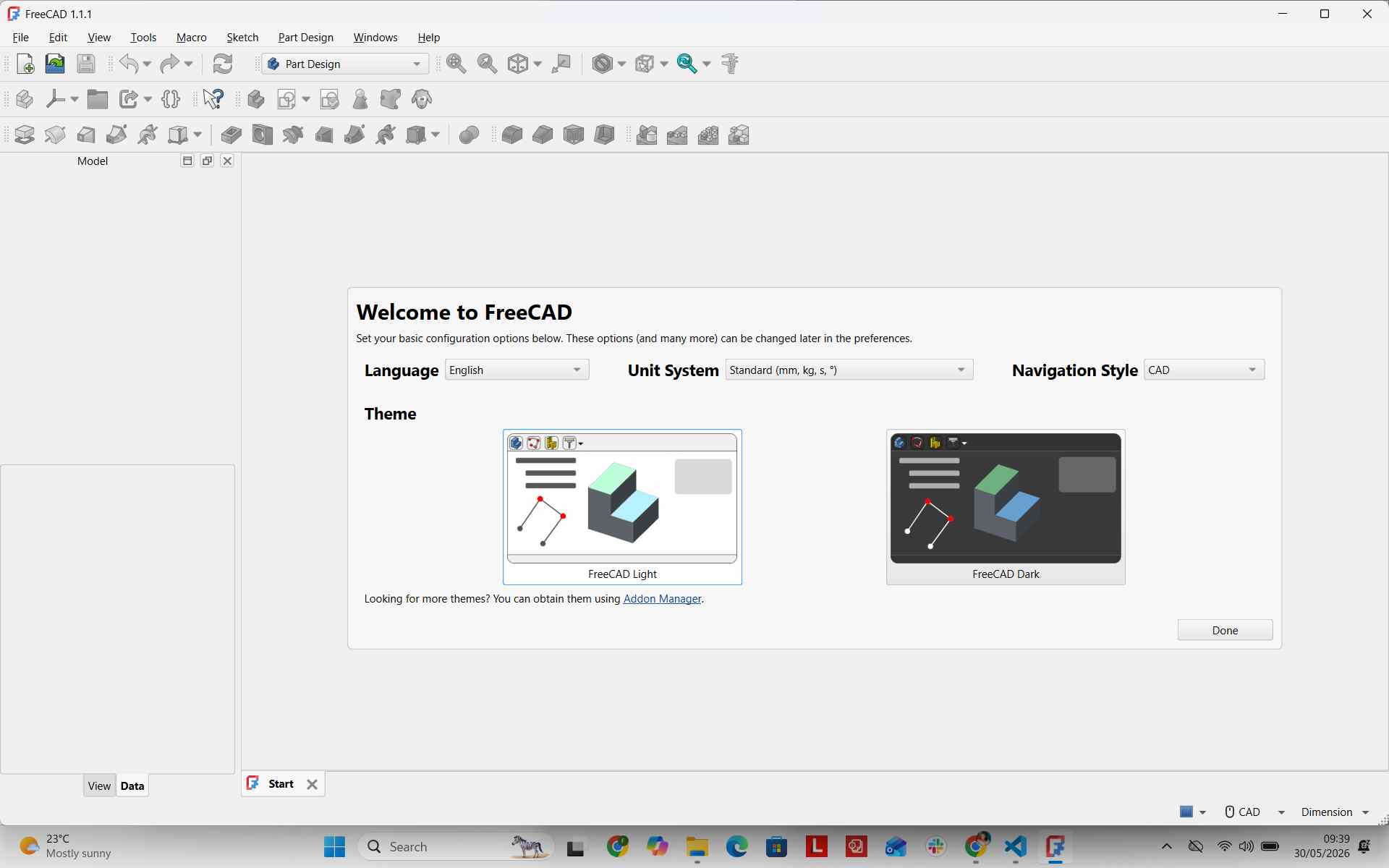
I launched FreeCAD and navigated to the Part Design Workbench.
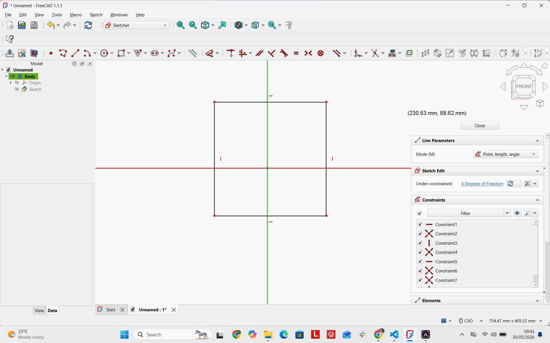
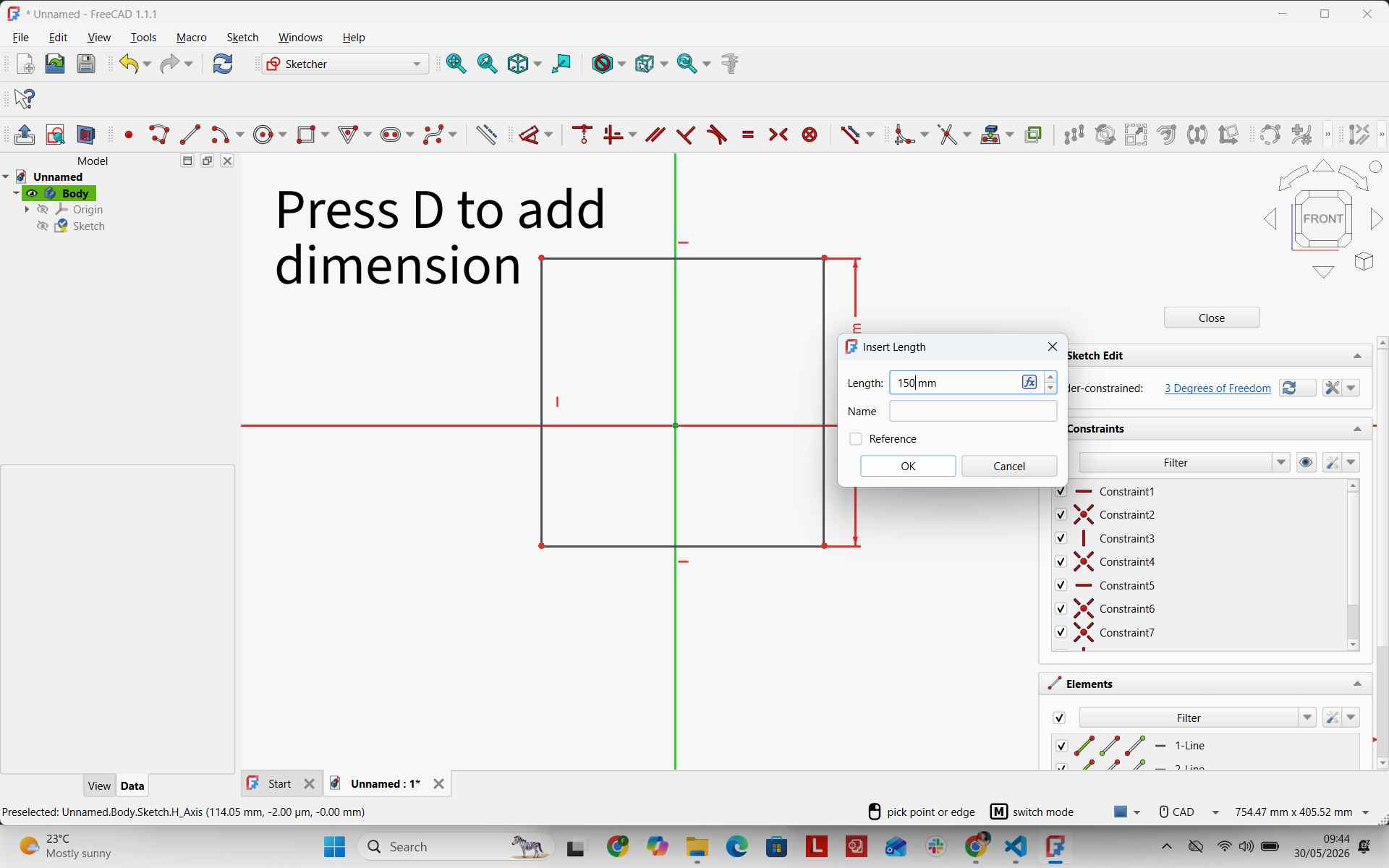
I sketched a base rectangle using sketcher lines and constraints.
Pressing D on the keyboard allowed me to add geometric dimensions to the profile.
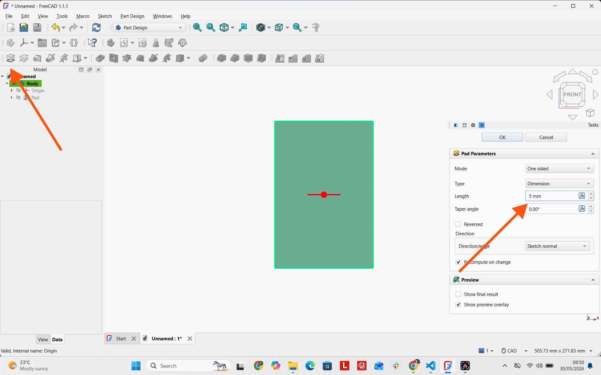
I extruded the sketch profile to create a 5mm base thickness via Part Design → Pad.
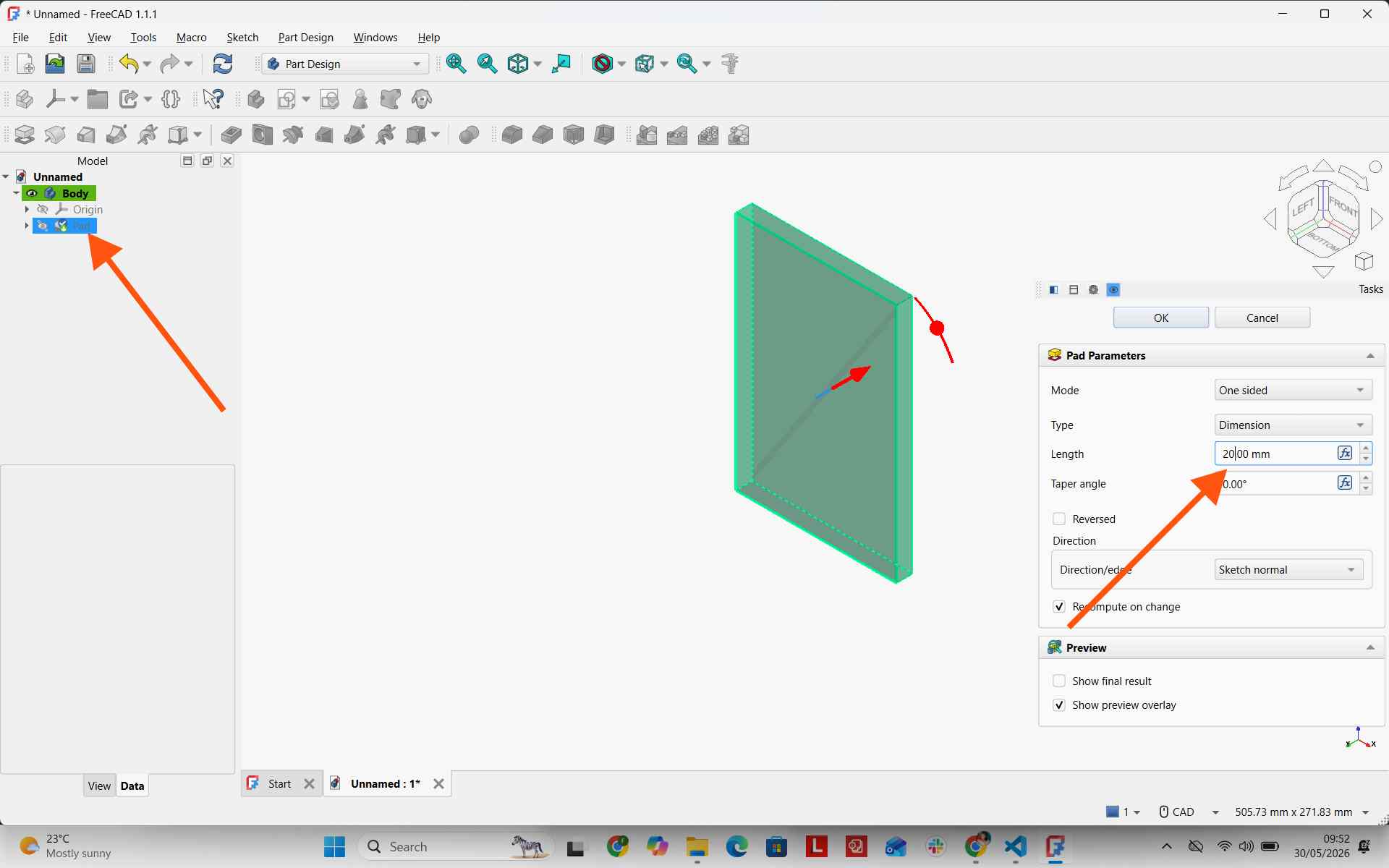
I updated the pad length to 20mm to accommodate internal electronic components.
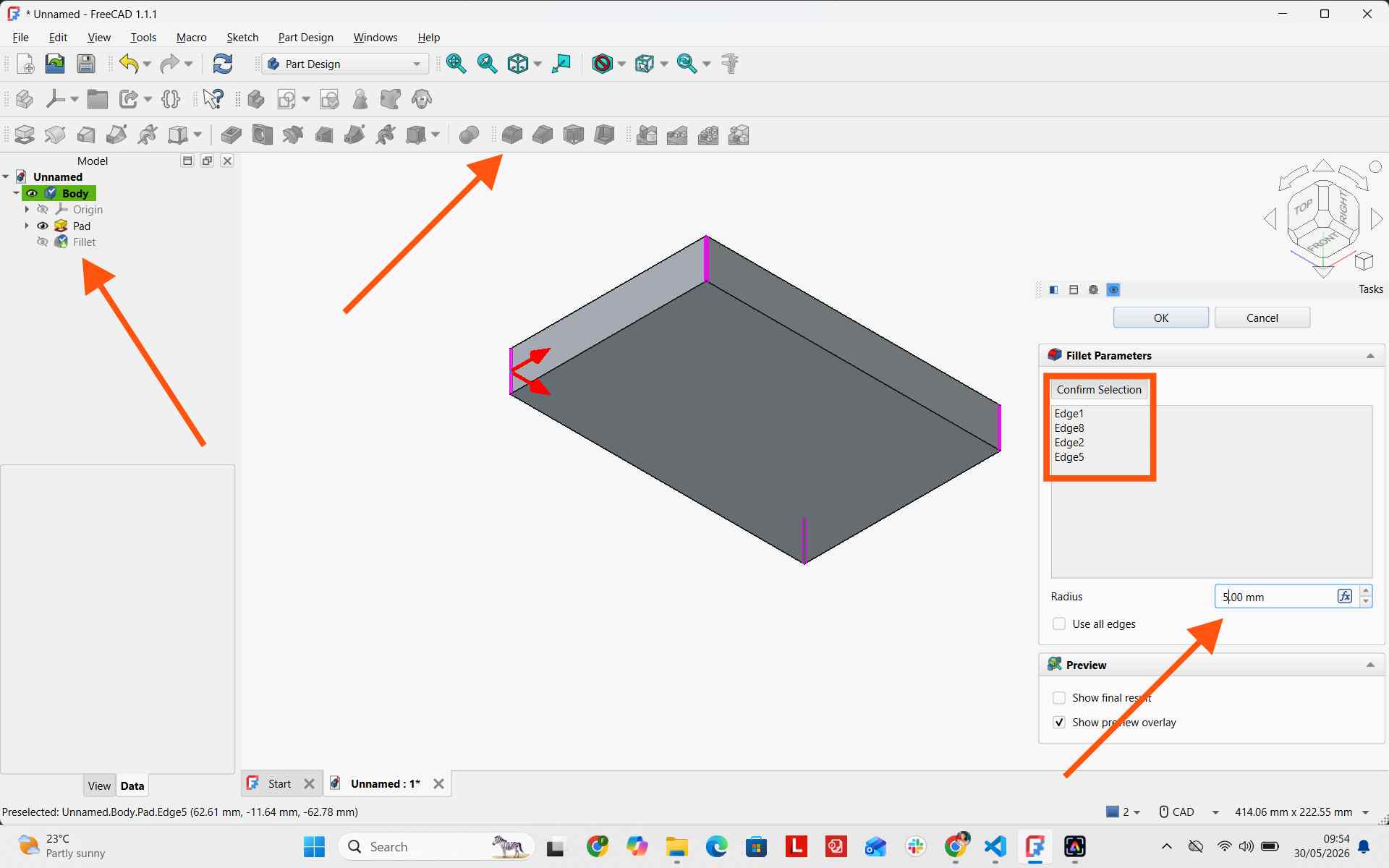
I applied 5mm fillets to round the external enclosure corners.
I added sketch circles for the Date/Month/Year discs and main hour display, extruding them 5mm outward.
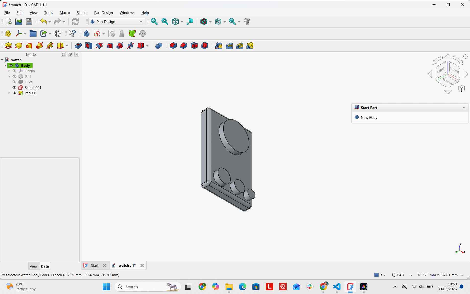
I applied custom material appearances to differentiate display elements from the main housing body.
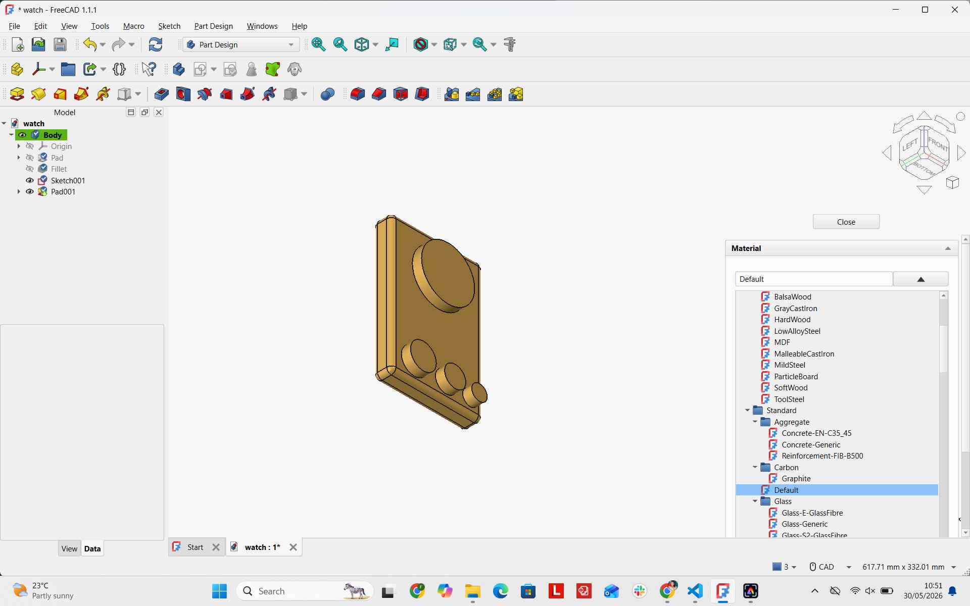
Final FreeCAD Design Model
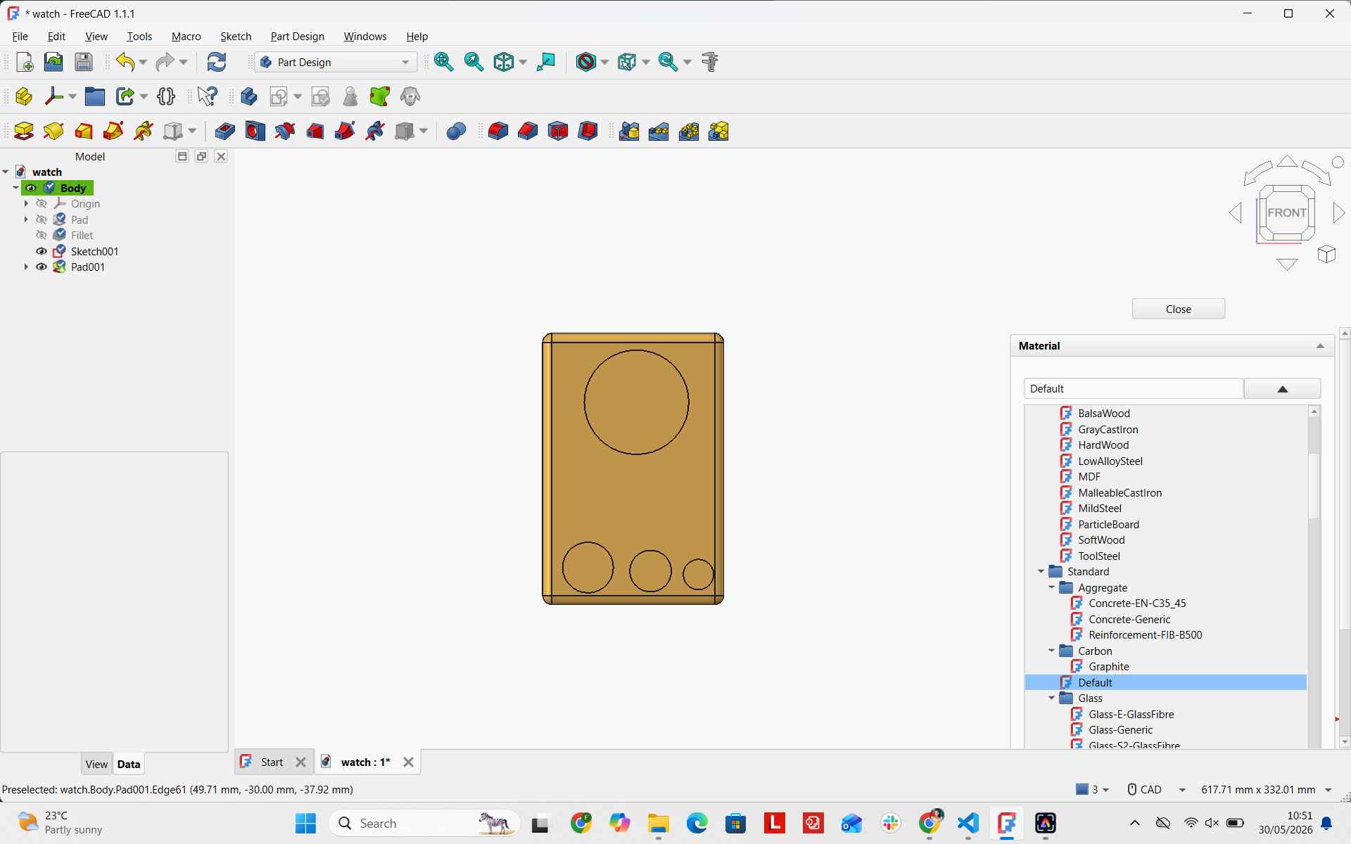
Connection to Final Project
The AURA Smart Clock modeled during this assignment serves as the blueprint for my final project. The 2D vector work established UI element placement, while the 3D modeling helped define internal structural clearance and enclosure assembly details required for physical fabrication.
Rendering, Animation, and Simulation in SolidWorks
1. Rendering
Rendering converts raw 3D CAD geometry into photorealistic images by applying materials, textures, lighting, shadows, and reflections.
To assign materials: Right-click model → Appearance → Plastic → Medium Gloss → Blue Medium Gloss Plastic.
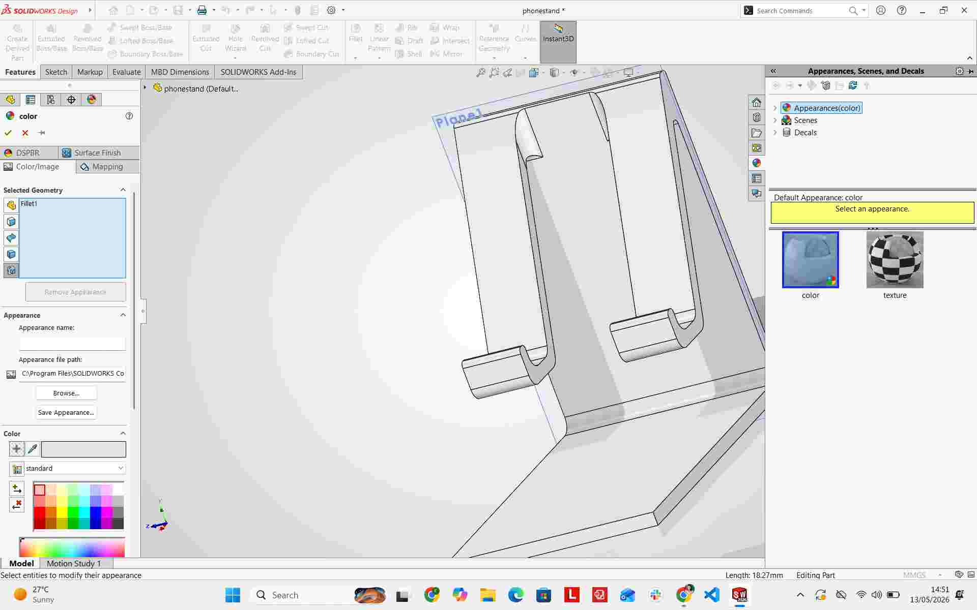
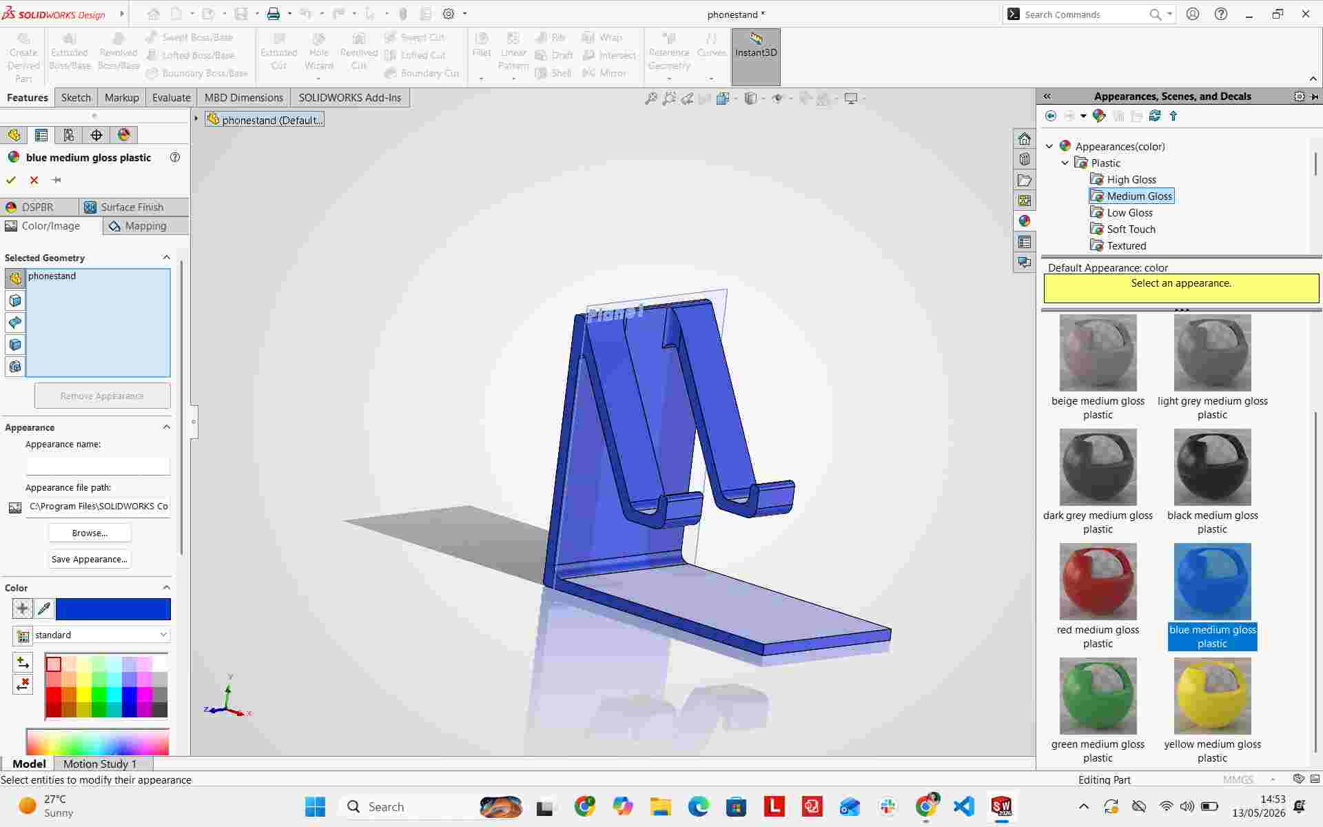
Purpose of Rendering
- To visualize the final product realistically
- To improve design presentation and communication
- To evaluate colors and materials before fabrication
- To create professional documentation images
2. Animation (Motion Study)
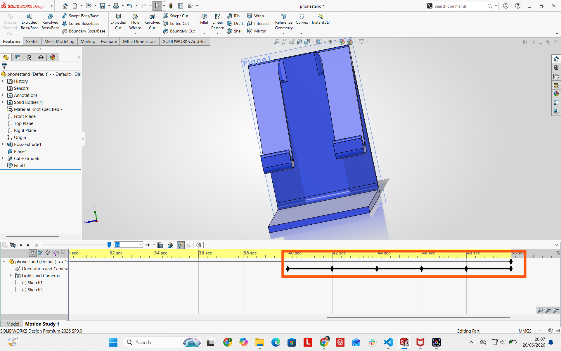
Animation illustrates product motion across time using the SolidWorks Motion Study tool and keyframes.
I opened the Motion Study tab to initiate the animation sequence.
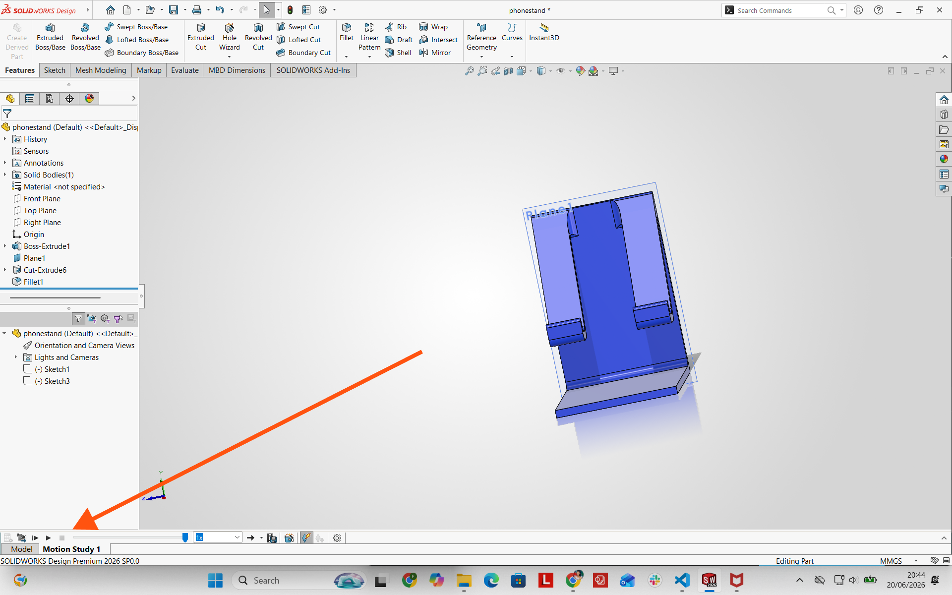
Under Orientation and Camera Views, I configured viewport control keyframes.
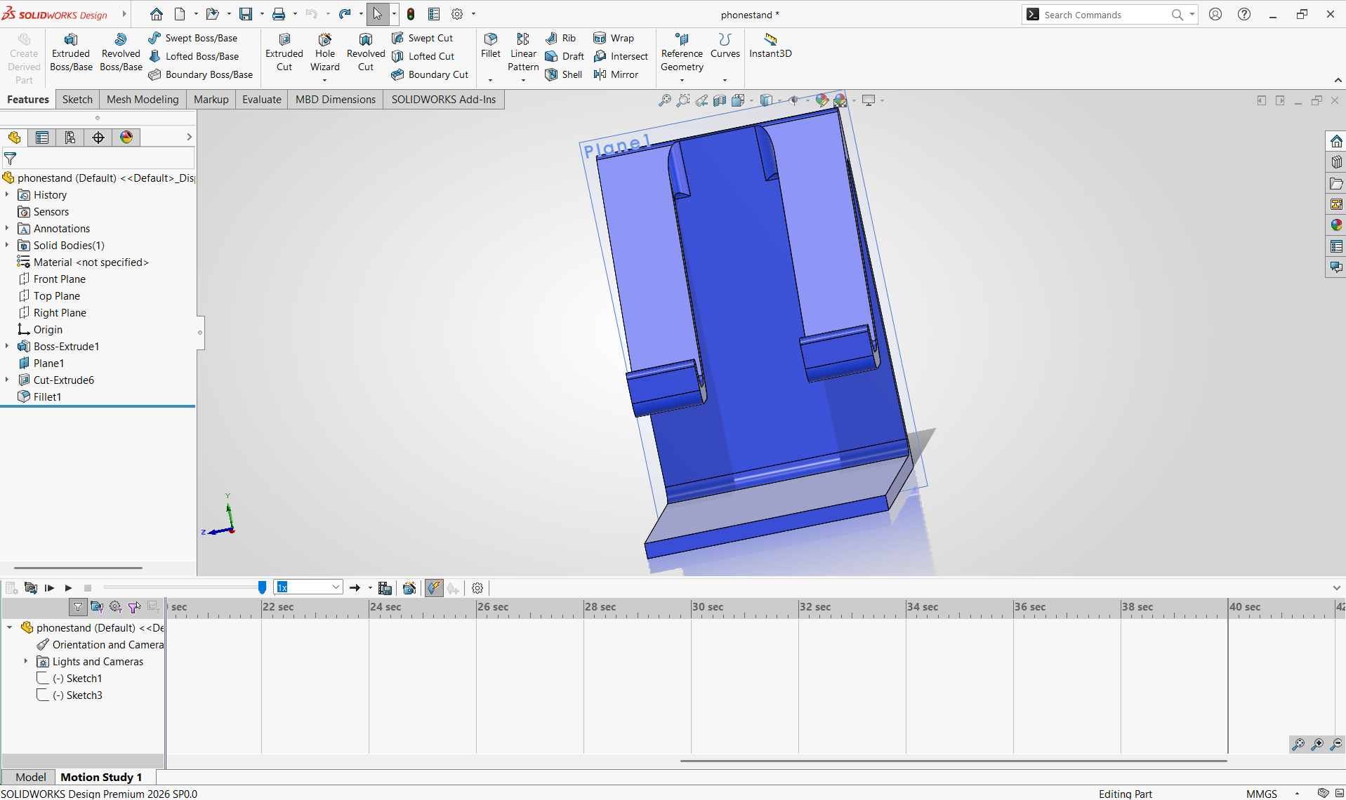
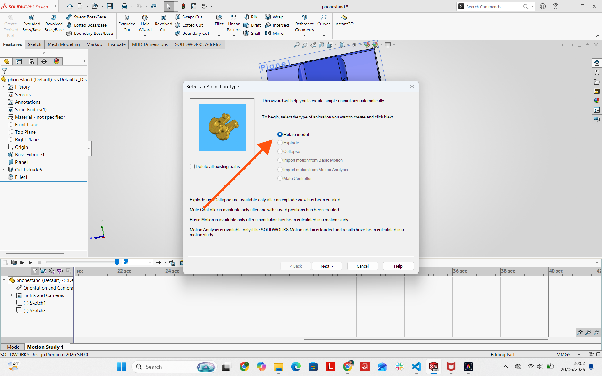
I launched the Animation Wizard tool.
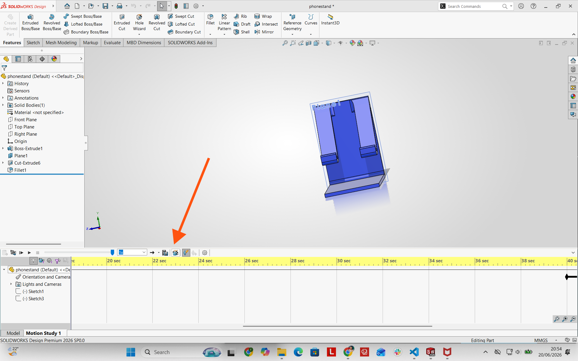
I selected Rotate Model as the animation type.
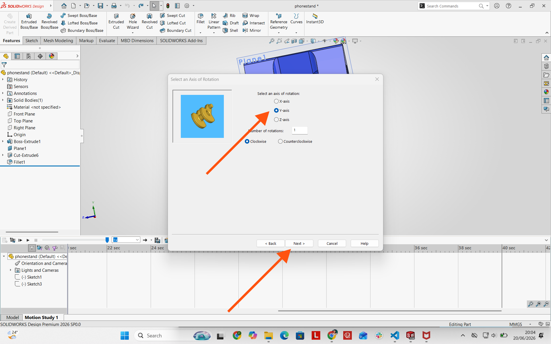
I specified rotation along the Y-axis and clicked Next.
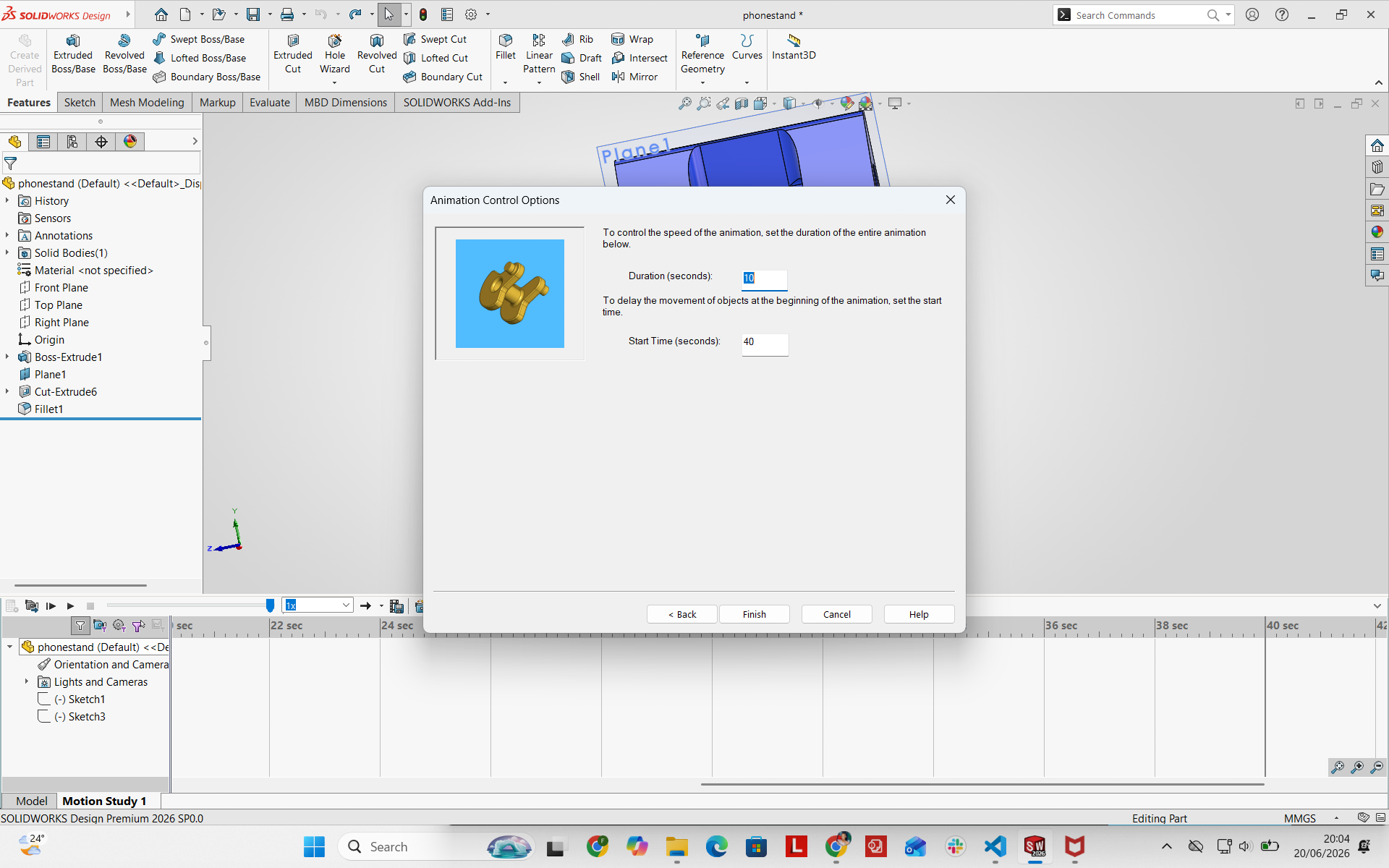
I set the animation duration and start time parameters.
I calculated and previewed the rotational sequence.
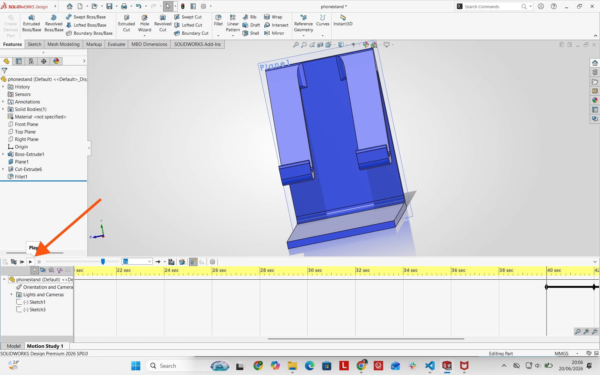
Simulation
I performed a static FEA study in SolidWorks Simulation to evaluate stress distribution and structural deformation under applied mechanical loads.
1. Simulation Setup
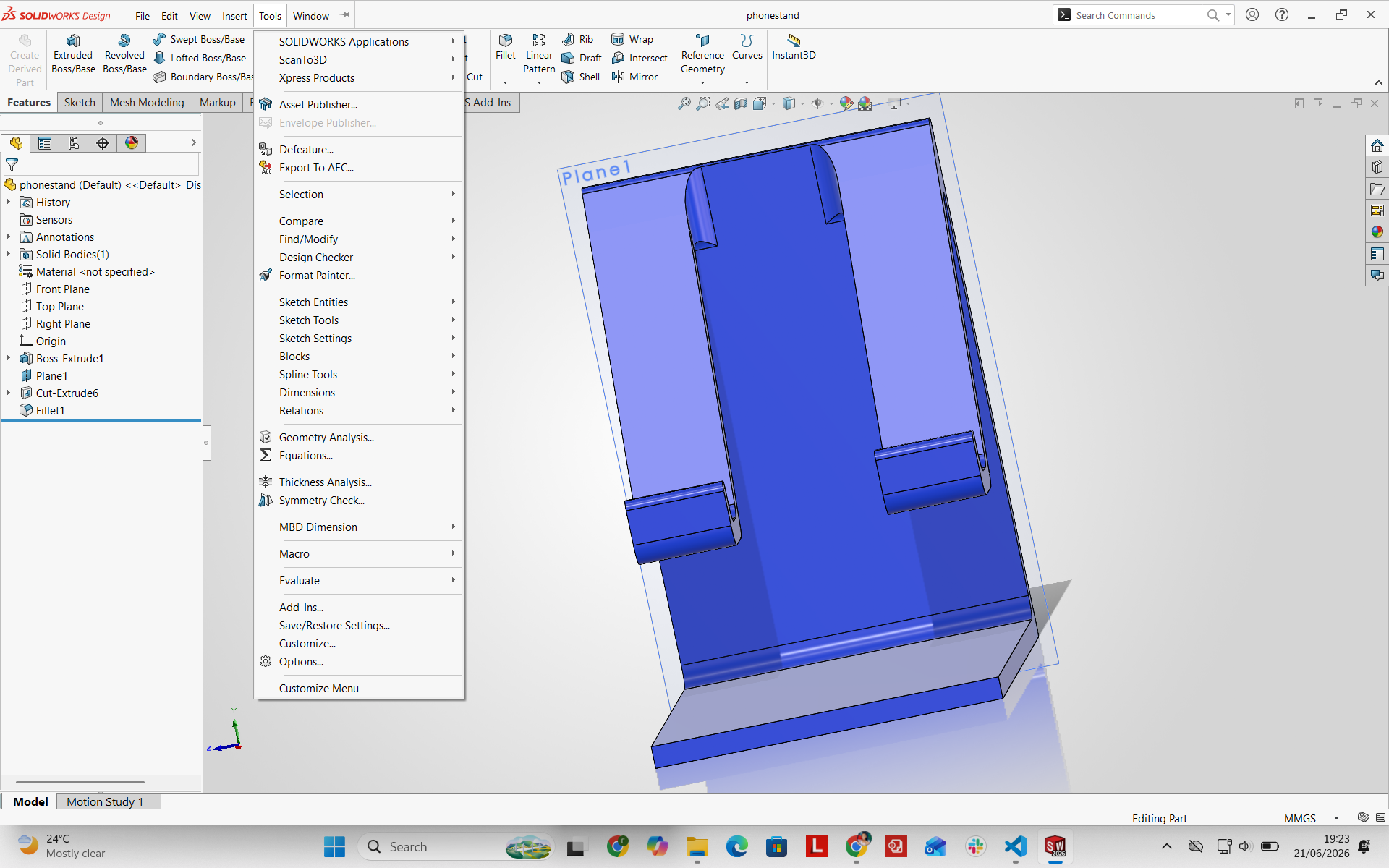
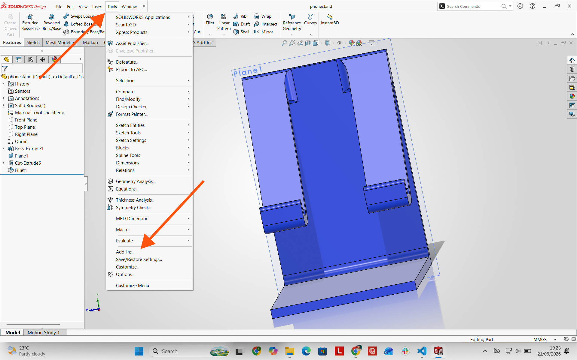
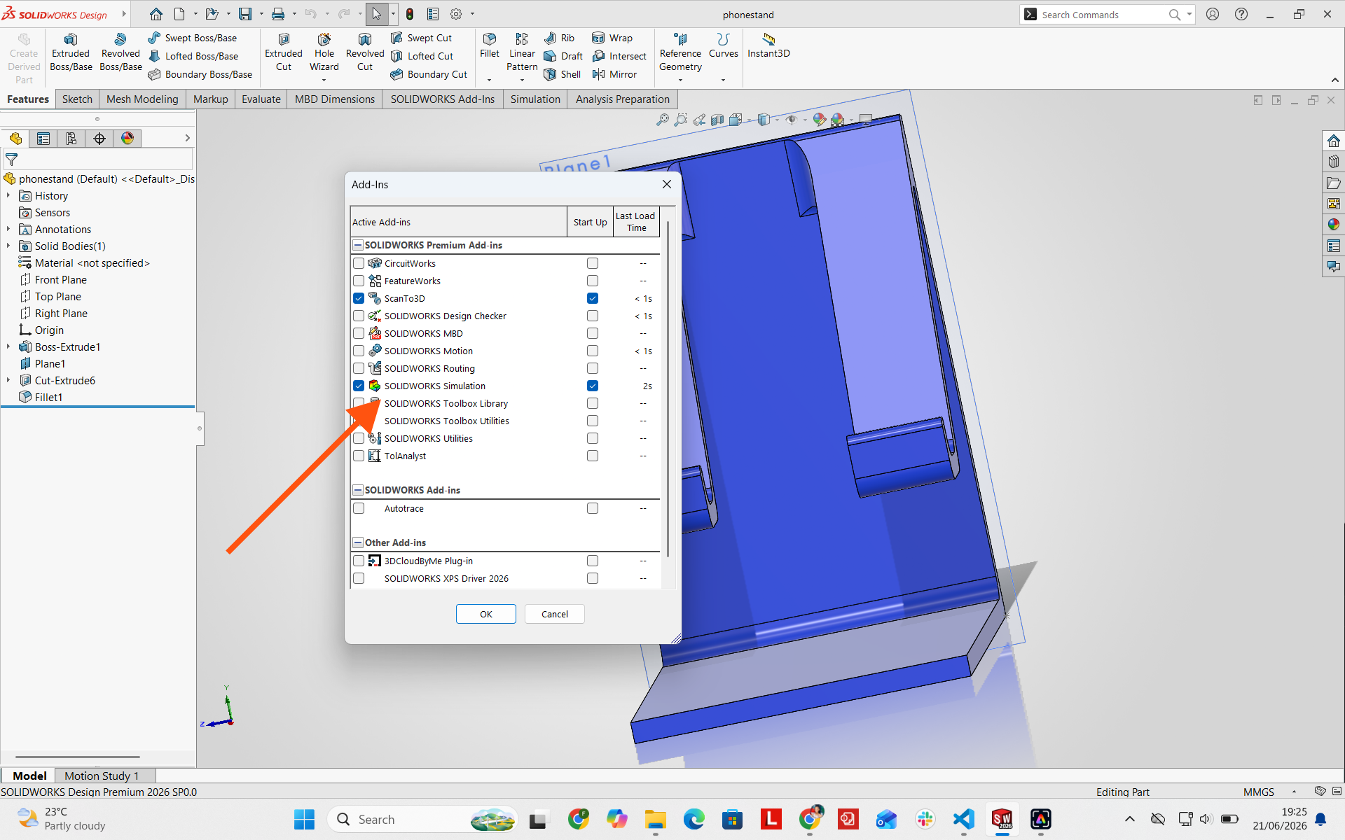
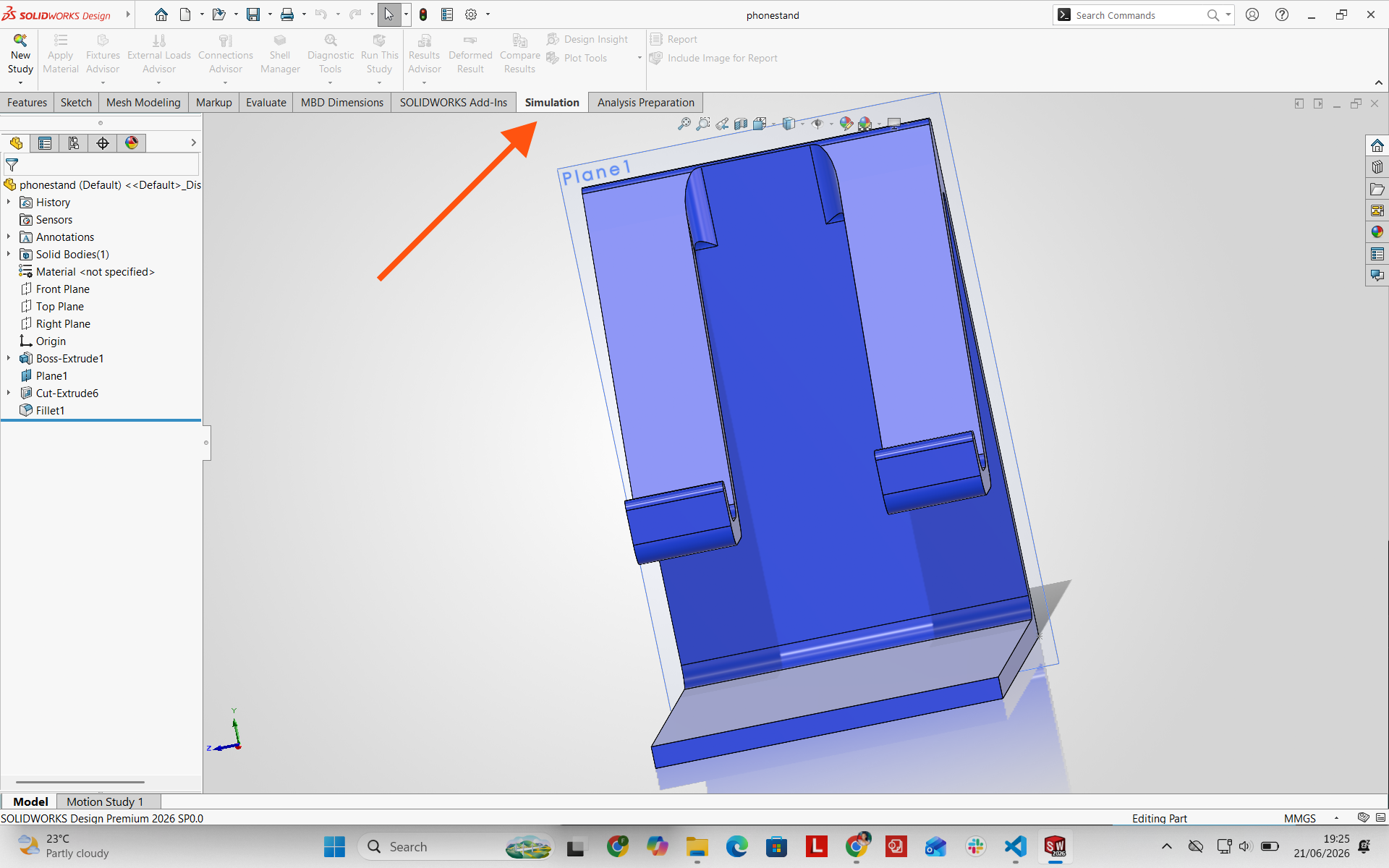
To enable the FEA tools: Tools → Add-Ins → SolidWorks Simulation.
2. Material, Fixtures and Loads
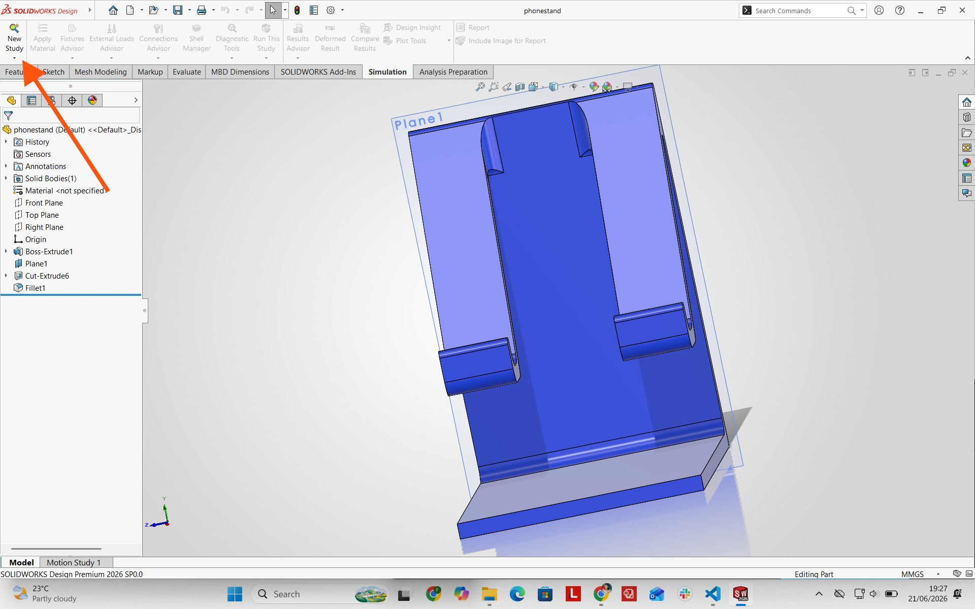
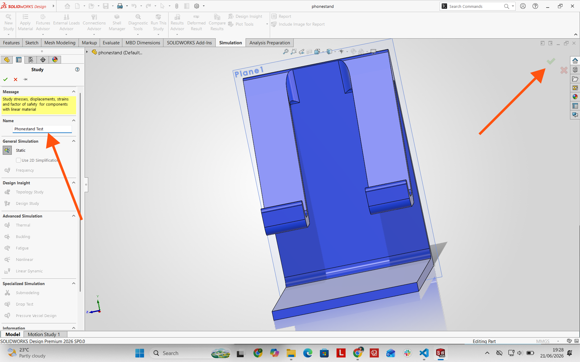
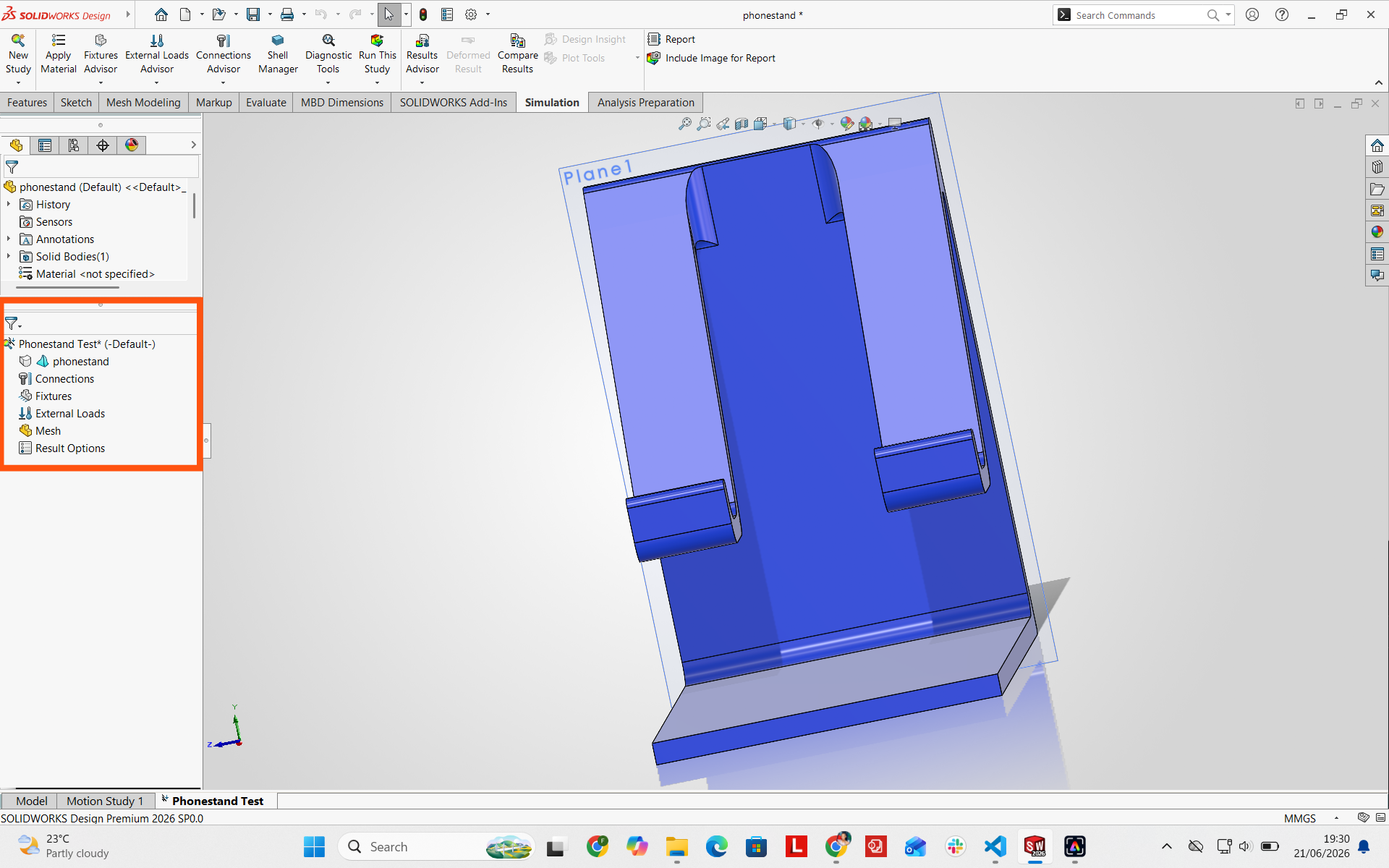
I created a new Static Study named phonestand test.
Applying Fixtures
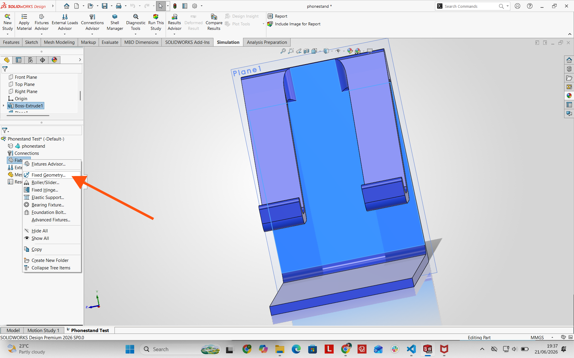
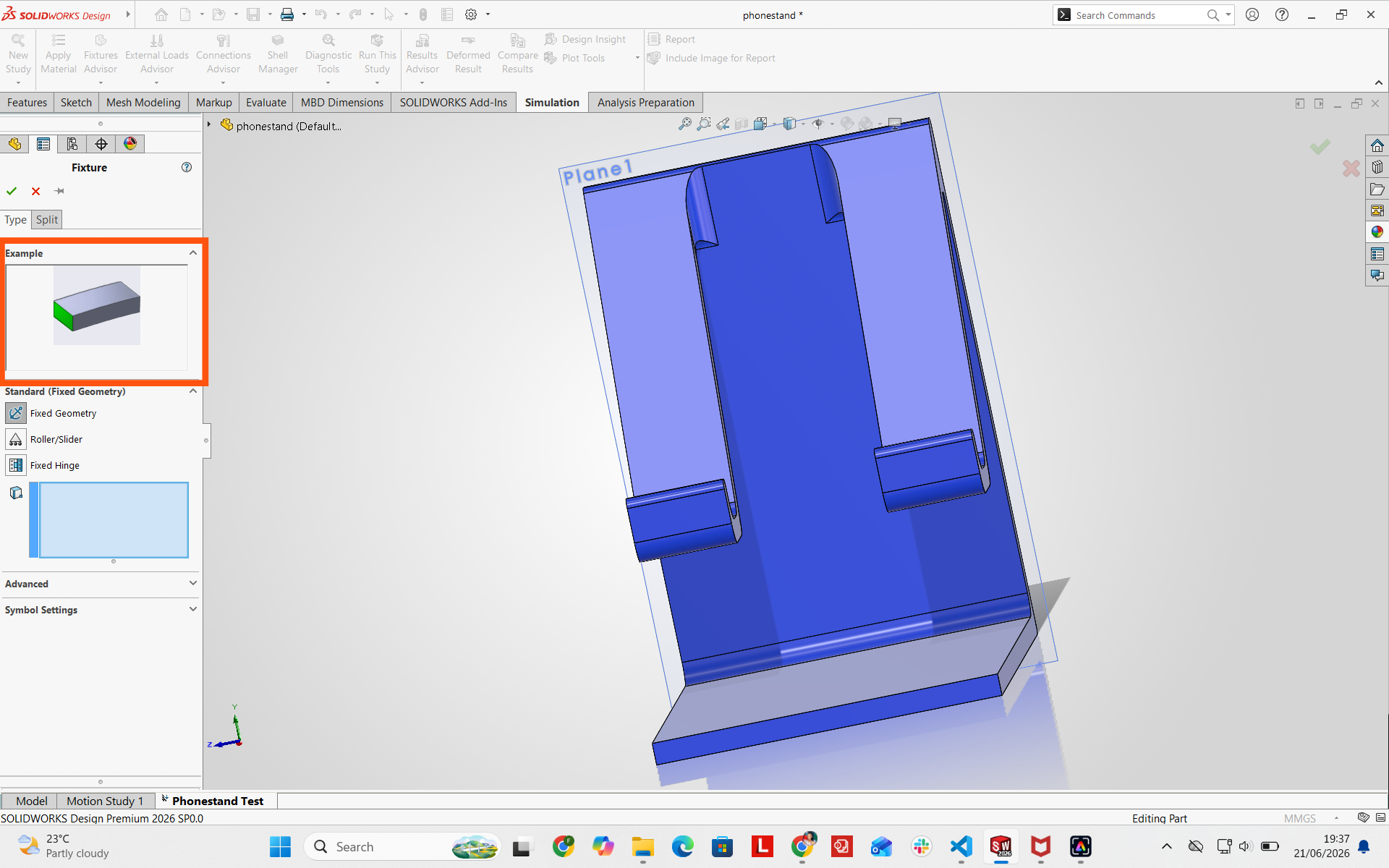
Fixtures define boundary constraints by locking specific faces in space to model fixed contact points.
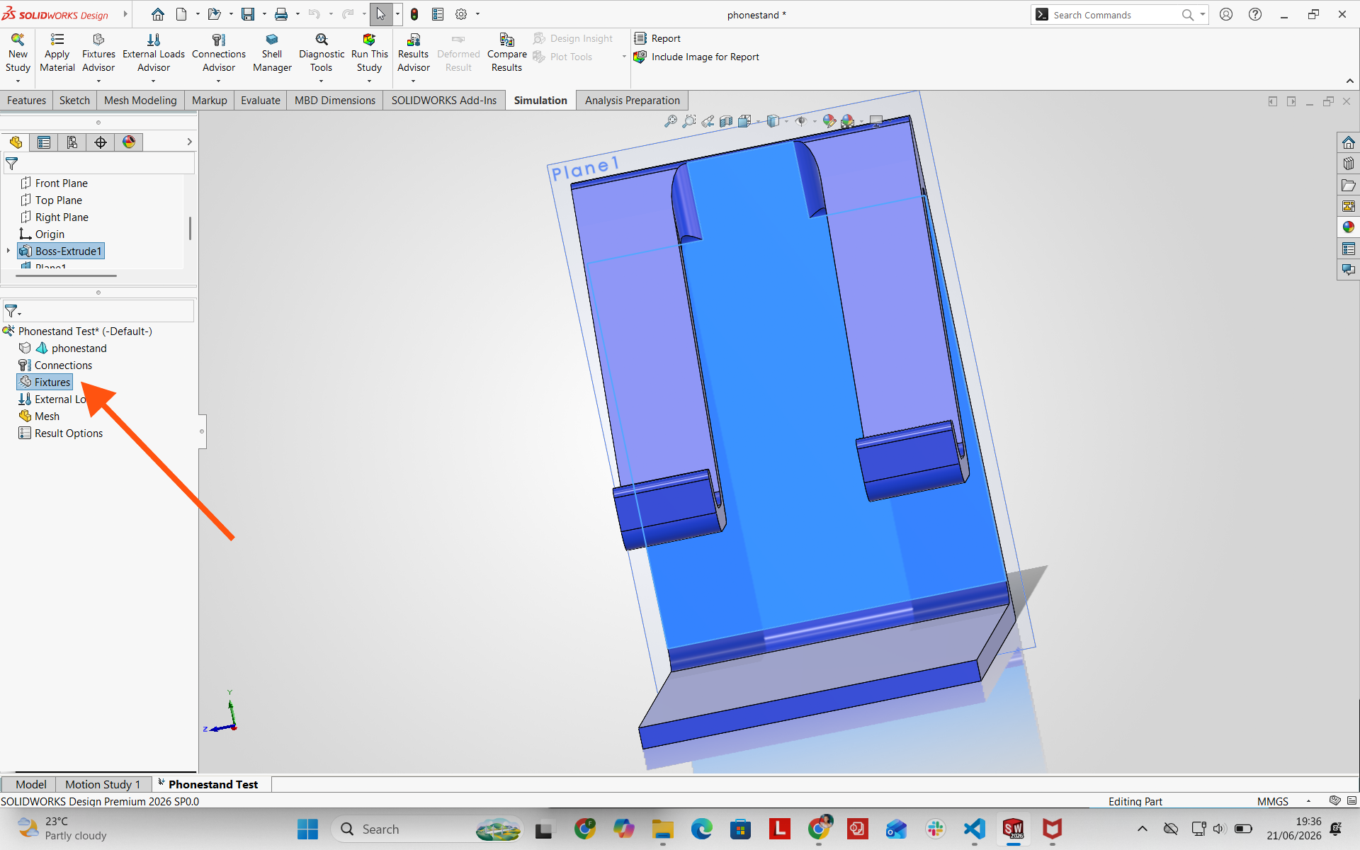
I applied Fixed Geometry constraints to the bottom face of the base.
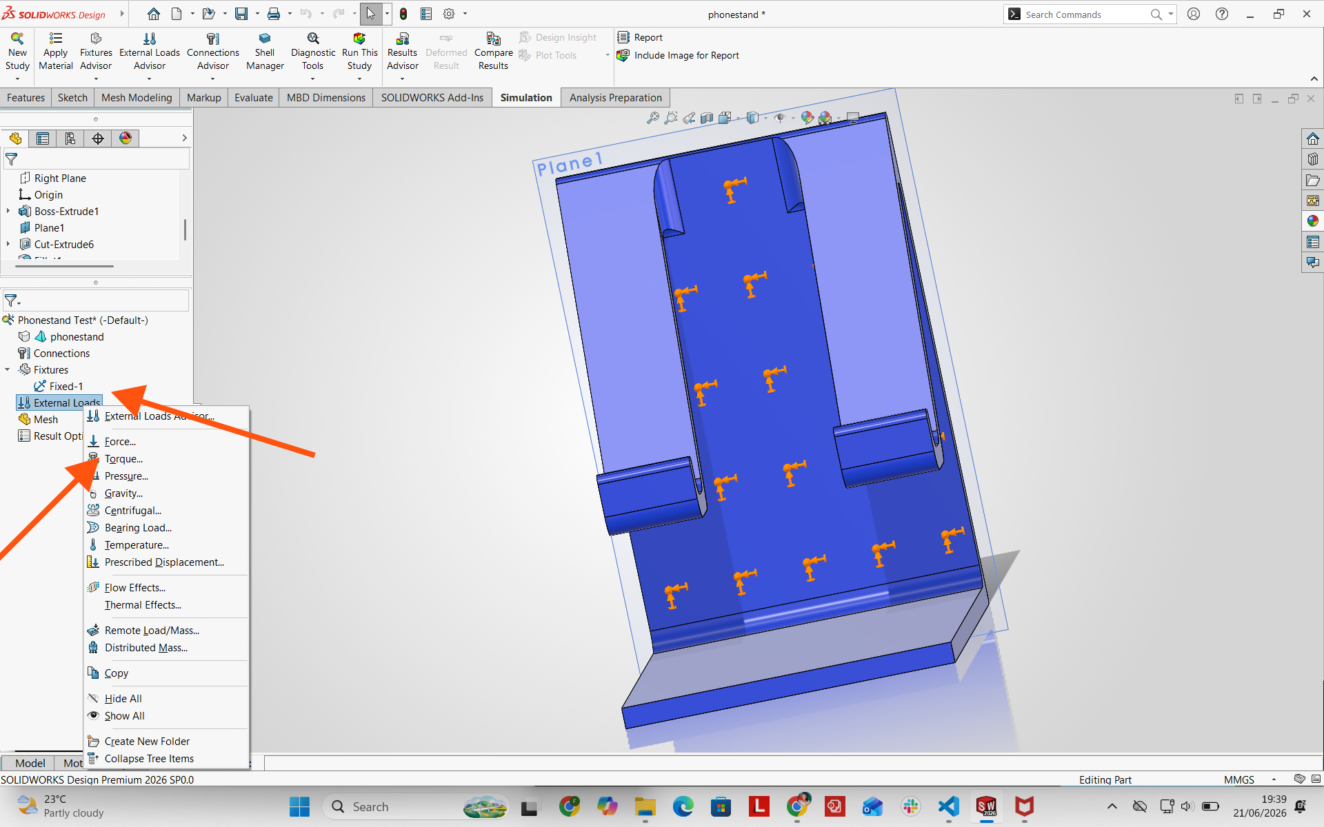
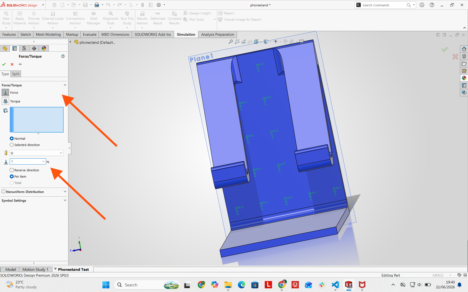
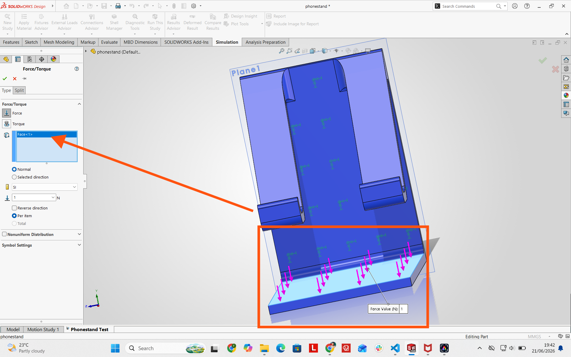
Applying External Loads (Force and Torque)
I applied a normal force of 1 N to the resting surface, alongside a minor torsional load, to evaluate linear stress and rotational tendency.
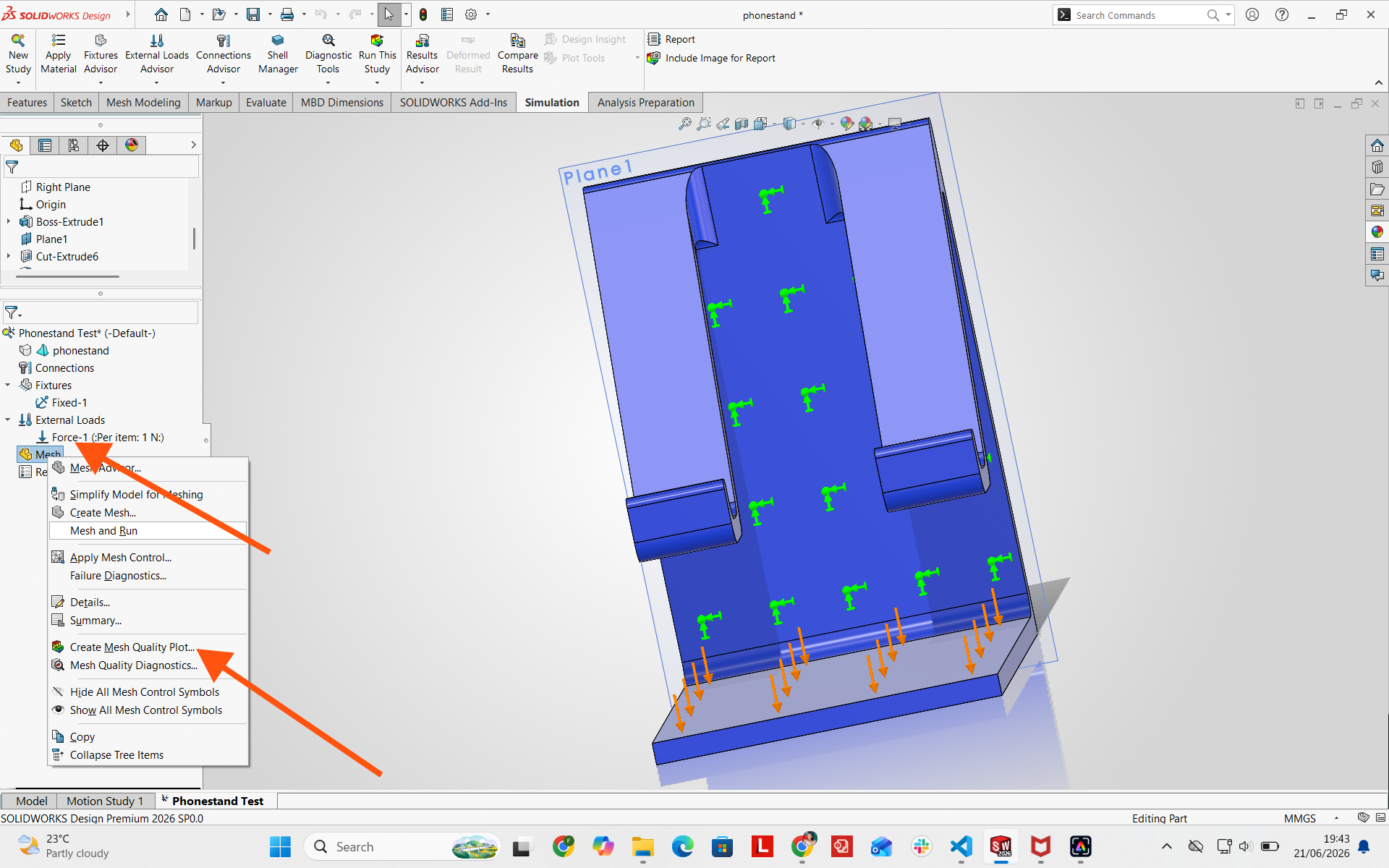
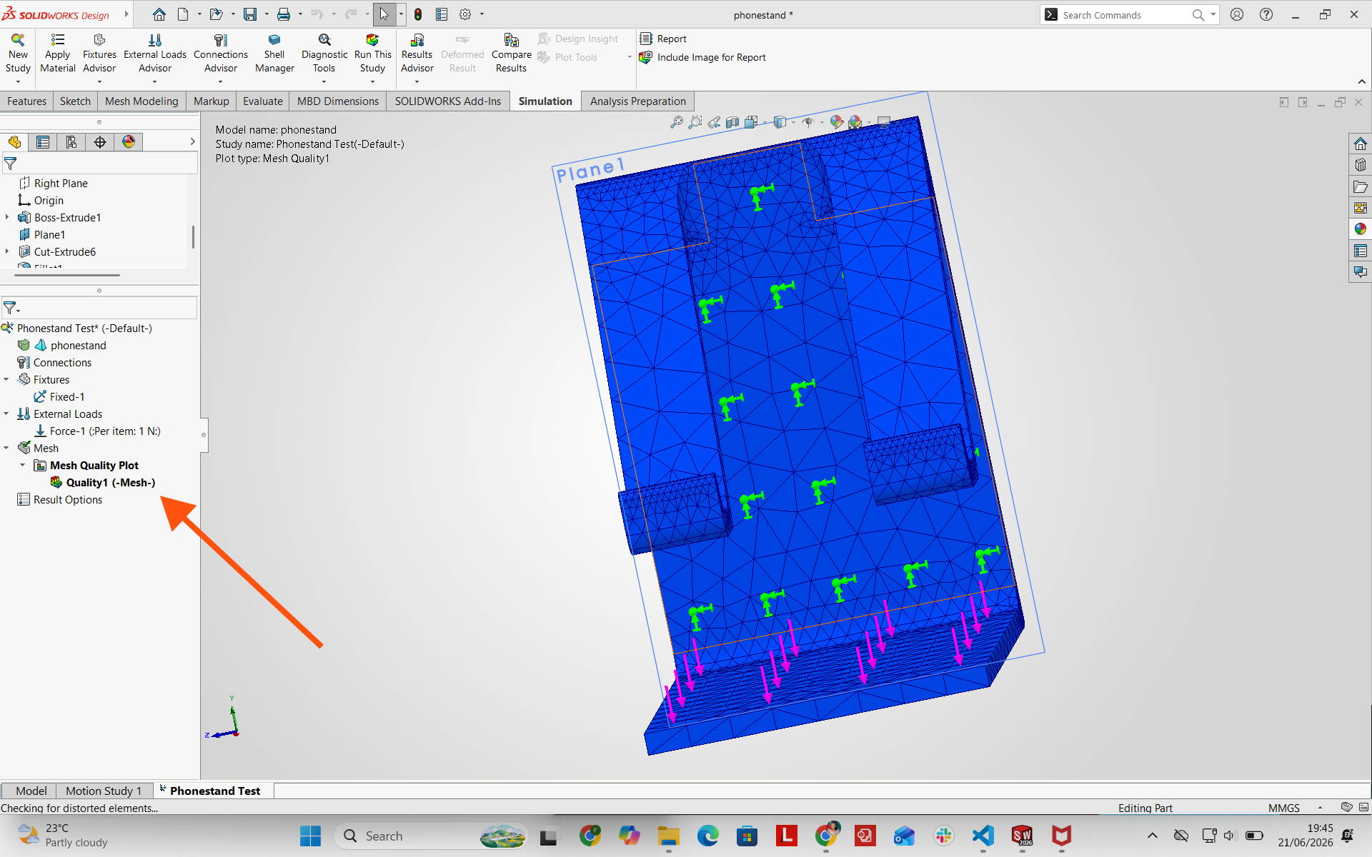
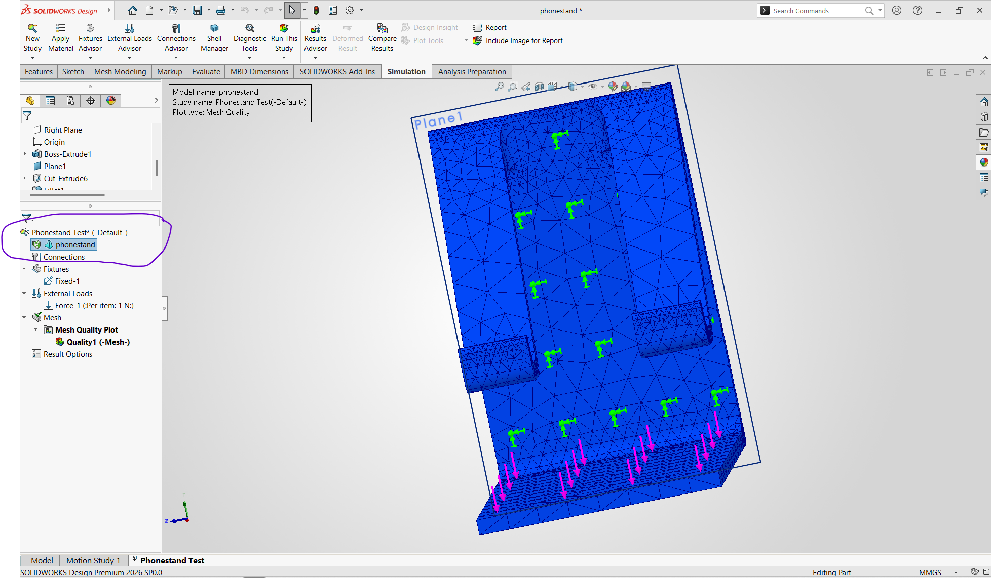
Mesh Generation & Mesh Quality
A finite element mesh was generated to discretize the solid body into solid tetrahedral elements for numerical analysis.
Material Assignment Requirement
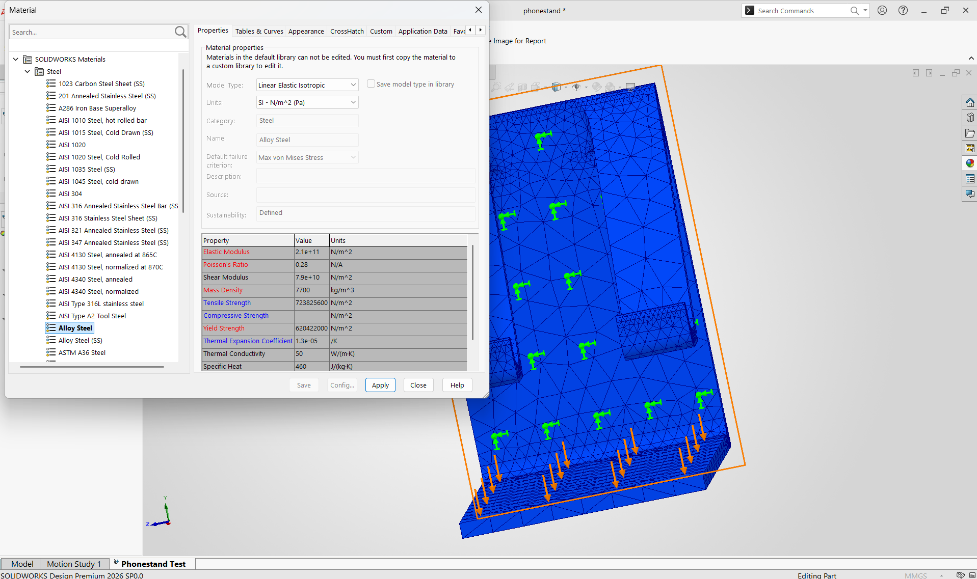
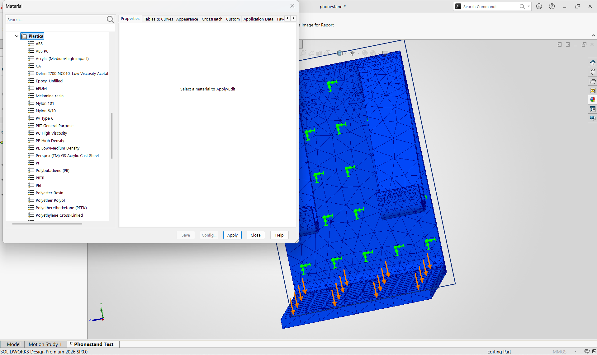
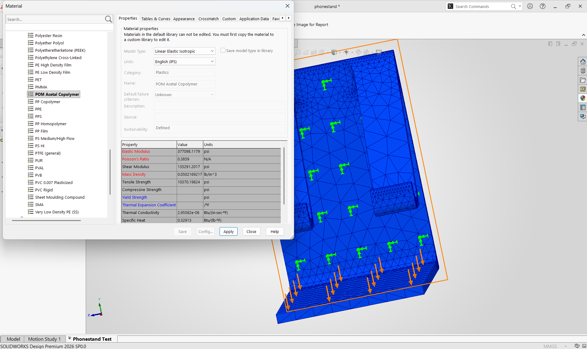
Since the initial run halted due to undefined material properties, I assigned a plastic material to provide density, Poisson's ratio, and yield strength parameters.
Right-click model name → Apply/Edit Material → ABS Plastic → Apply.
Simulation Video
The video below details mesh generation, solver computation, and Von Mises stress plot visualization.
Image and Video Compression
- Images were compressed using MiniWebTool (reducing file size from ~400 KB down to ~80 KB).
- Videos were compressed using HandBrake to reduce resolution and overall bitrate.
Image Compression Process
Here is video showing the process of compressing images using MiniWebTool Image Compressor.
To ensure fast web loading times, I optimized all media assets:
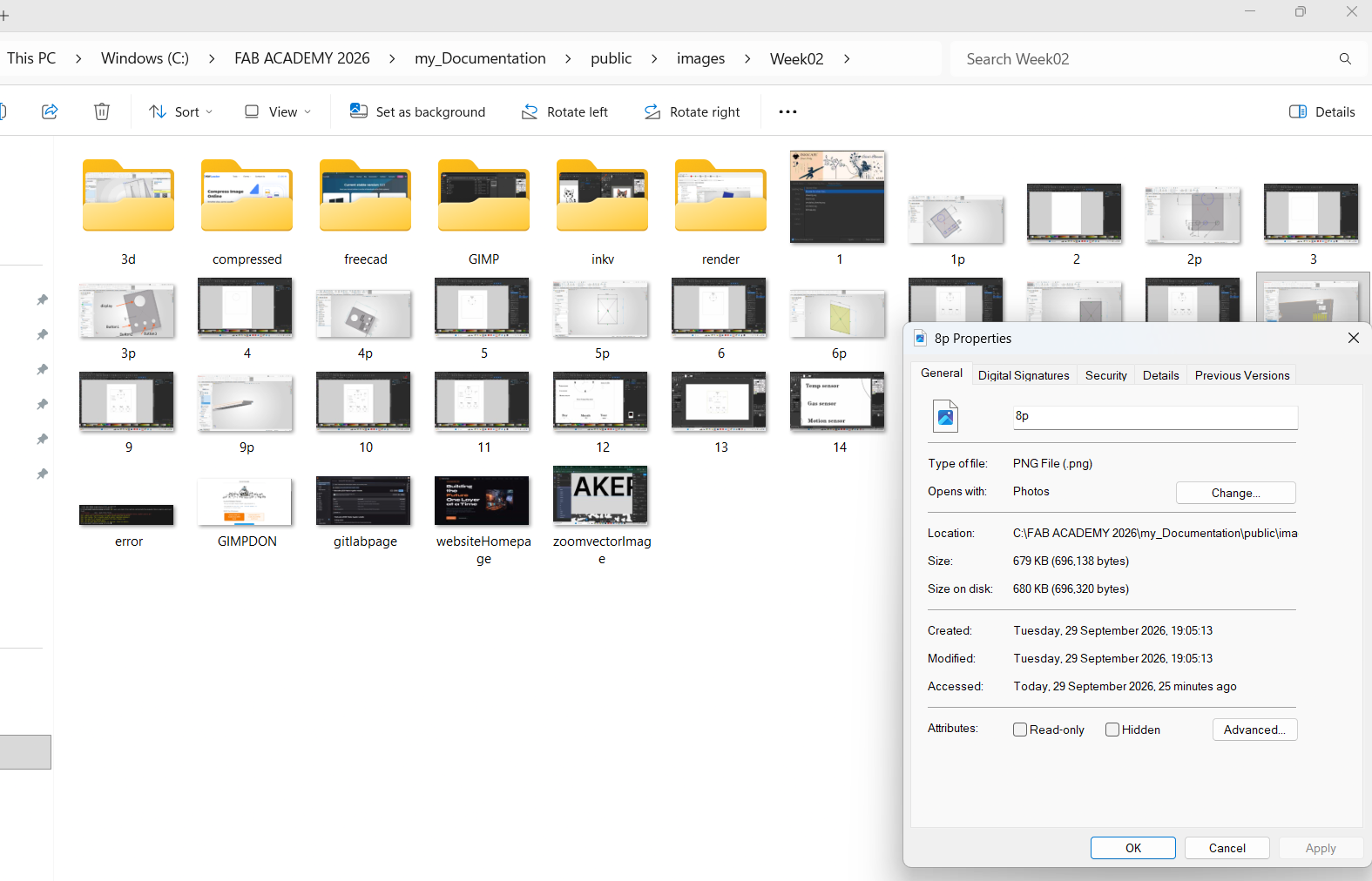
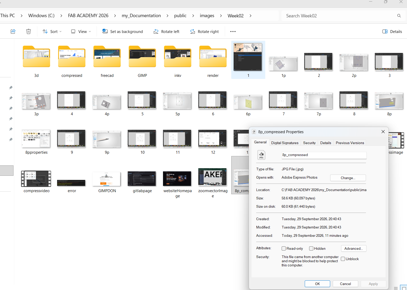
Here is the comparison of the original image and the compressed image. The original image was 680 KB, while the compressed image is only 60 KB, resulting in a significant reduction in file size without noticeable loss of quality.
Properties of Original Image
Properties of Compressed Image
Video Compression Process
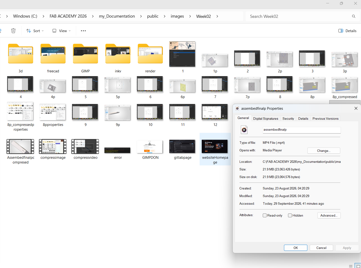
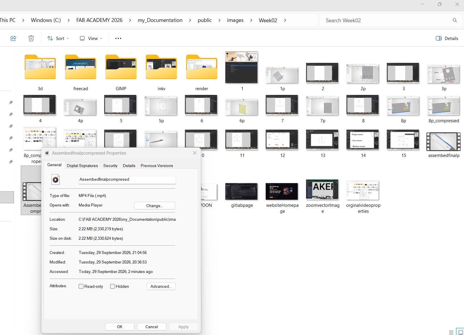
Here is a video demonstrating the complete process of compressing a video from 1080p to 720p using HandBrake, reducing the file size from 21 MB to just 2.2 MB.
Properties of Original Video
Properties of Compressed Video
Downloads & Design Files