Two wildcard processes not covered in any other week: a computer-vision system for real-time
3D-print failure detection, and computer-controlled machine embroidery.
Wildcards (Click sections to view)
Project OverviewComputer Vision
For this Wildcard I worked with computer vision — a digital process not covered by
any other Fab Academy assignment and it is in the examples of wildcard projects (Machine Learning and Machine Vision). I designed, trained and deployed a computer-vision system that
detects one of the most common failures in FDM 3D printing: the spaghetti failure.
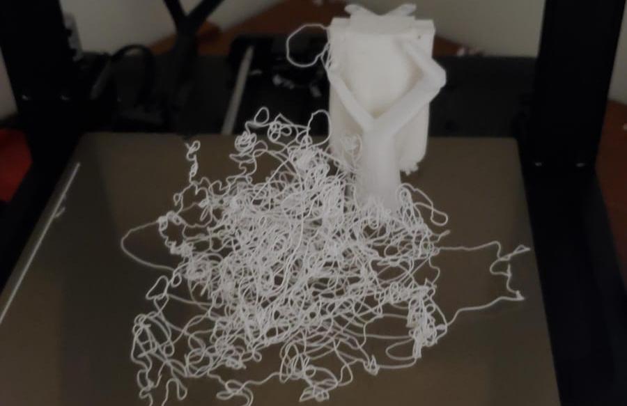
A spaghetti failure occurs when the printer continues extruding filament incorrectly after a print detaches or fails, creating tangled strands of material that resemble spaghetti. These failures can waste large amounts of filament and printing time if they are not detected quickly.
The goal of this project was to create a low-cost embedded computer-vision system capable of:
Monitoring a 3D printer in real time
Detecting spaghetti failures using computer vision
Sending remote notifications automatically
Turning on a warning LED (on a XIAO connected over Bluetooth) when a failure is detected
Streaming live video through a web interface
Running directly on a Raspberry Pi 5
The system combines computer vision, embedded systems, networking, and real-time processing into a single integrated solution, processed entirely on the edge without any cloud dependency.
Why This Qualifies as WildcardScope Justification
The Wildcard week asks for a digital design-and-production process not covered by any other
Fab Academy assignment, documenting the requirements it meets and including everything
needed to reproduce it. The digital process I chose is computer vision: designing a
visual detection pipeline, producing a trained detection model from a curated image dataset, and
deploying it for real-time inference on embedded hardware. None of the other weeks teach or require
this.
Computer vision is a complete digital workflow with its own "design" and "production" stages, just in
the visual/data domain rather than the material domain:
Design (CAD-equivalent): defining the detection problem, designing and curating the image dataset, choosing the model architecture, and setting the training/preprocessing parameters.
Production (CAM-equivalent): training the model to produce a concrete, reusable artifact — the trained weights file (best.pt) — and deploying it to run on real hardware.
Reproducibility: the dataset source, the cleaning steps, the architecture, the hyperparameters and the deployment stack are all documented on this page, so the result can be reproduced end to end.
To make the "not covered elsewhere" point explicit, here is why this work does not overlap with the
other assignments, even though it touches some of the same hardware:
Assignment
Why this project is different
Week 4 — Embedded Programming
That week covers microcontroller programming. Here the central work is the computer-vision pipeline — training a detection model and running visual inference on a Raspberry Pi 5 — which is computer-level vision processing, not microcontroller firmware.
Week 9 — Input Devices
A camera is used only as an image source. The assignment is not about reading a sensor, but about the computer-vision model that interprets the image stream.
Week 11 — Communication
MQTT/ntfy and HTTP streaming are supporting features here, not the focus. The novel contribution is the trained vision model, not the network link itself.
Week 14 — Interface Design
The web view only displays the vision output. The engineering effort is in the detection pipeline (dataset, training, inference), not in building a GUI.
Week 15 — System Integration
That week integrates the parts of the final project. This Wildcard develops a standalone capability — computer vision — that is new in its own right.
Week 17 — Applications and Implications
That week analyzes the project; here the work is the actual design, training and deployment of a computer-vision model.
In short, the unconventional digital process that makes this a Wildcard is the
computer-vision workflow: designing and cleaning an image dataset, producing a
trained detection model, and deploying it for real-time inference on embedded hardware — none of
which is covered by any other week.
Requirements MetAssignment Checklist
The Wildcard brief asks to design and produce something with a digital process not covered in
another assignment, document the requirements it meets, and include everything needed to reproduce
it. This table maps each requirement to where it is satisfied on this page:
Requirement
How this project meets it
A digital process
Computer vision: dataset design, model training, and embedded inference.
Not covered in another assignment
See the comparison table above — no other week involves training or deploying a vision model.
Design and produce something
The produced artifact is a trained detection model (best.pt) running live on the Pi, plus the working monitoring system around it.
Dataset source (Roboflow), cleaning steps, architecture (YOLOv11n), preprocessing (grayscale), hyperparameters, and the deployment stack (Picamera2 + OpenCV + Ultralytics on a Pi 5) are all documented below.
Problem Definition3D Printing Failures
FDM 3D printers can operate for many hours continuously, making constant supervision difficult. One of the biggest risks during long prints is a spaghetti failure, where the printer extrudes filament uncontrollably after losing proper layer adhesion or positional accuracy.
This matters because the failure rate in 3D printing is far from negligible: studies report that roughly 20% of prints fail, which leads directly to:
Wasted filament
Wasted time
Equipment wear
Additional operating costs
Potential damage to the hotend or moving components
Commercial solutions exist, but many are expensive or require cloud-based subscriptions. This project focused on creating an affordable standalone alternative using open-source tools and embedded hardware.
Example of a spaghetti printing failure during FDM manufacturing.
BackgroundPrior Work
Camera-based monitoring of additive manufacturing is not a new idea. As early as
2016, automated camera-based monitoring systems were developed that could
identify defects during the printing process (Everton et al., Materials & Design).
This project builds on that idea, but brings it onto affordable embedded hardware and pairs it
with a modern computer-vision detector and a remote alert system.
ObjectivesGoals
General Objective
Implement a computer-vision system capable of monitoring, detecting failures in 3D
prints, and alerting in real time.
Specific Objectives
Research computer-vision models and acquire a dataset to support training.
Train a computer-vision model to identify printing errors through a camera.
Integrate and evaluate the system on a real 3D printer and add an alert system.
Add a physical warning: light up an LED on a XIAO connected to the Raspberry Pi over Bluetooth when a failure is detected.
Justification
Early detection of errors in 3D prints reduces production costs, avoids material waste, and
improves the efficiency of the manufacturing process. Beyond that, using computer vision opens the
door to autonomous monitoring systems applicable in both academic and industrial environments.
Scope
Detect common errors in 3D prints using computer vision.
Monitor the printing process in real time.
Generate automatic alerts when a failure is detected.
Prevent loss of material and time on failed prints.
Dataset PreparationTraining Data
One of the most important parts of the project was preparing the dataset used to train the vision model.
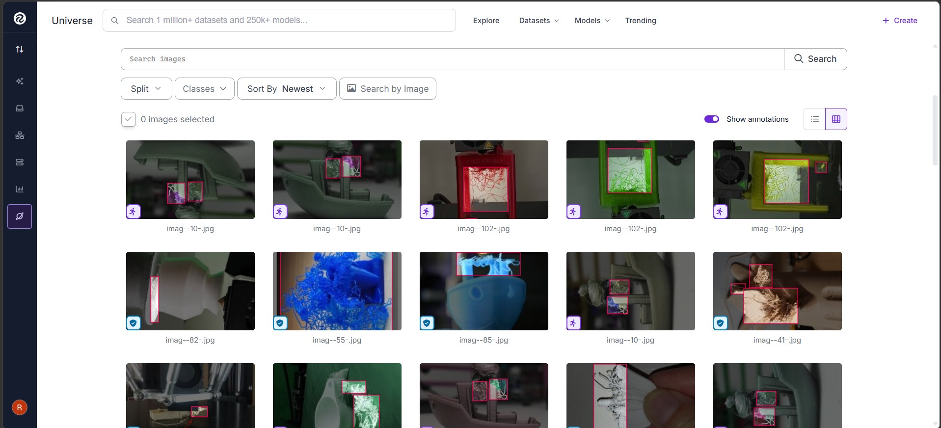
The dataset was obtained from Roboflow and other public sources, where several datasets related to 3D printing defects are available. After evaluating different options, I selected and exported a dataset focused on spaghetti failures to use as the base for training.
However, many of the available datasets had quality problems that had to be fixed:
Repeated labels
Badly named classes
Unnecessary categories
Because several of these categories were visually similar, the model initially produced many false positives. To improve performance, the following classes were removed from the dataset:
zits
stringing
blobs
Only the images related to spaghetti were kept, and the images and labels were
reorganized for training. The final dataset was also converted to grayscale in order to:
Reduce computational complexity and memory use
Improve embedded performance and processing speed
Focus on geometry instead of color
Reduce lighting and color dependency
Cleaning and filtering the Roboflow dataset for spaghetti-only detection.
Vision Model TrainingYOLOv11n
After researching and comparing different object-detection architectures, the vision model was
trained using the YOLOv11n architecture. This version was selected because of its:
Low computational load
Fast inference speed
Compatibility with the Raspberry Pi 5
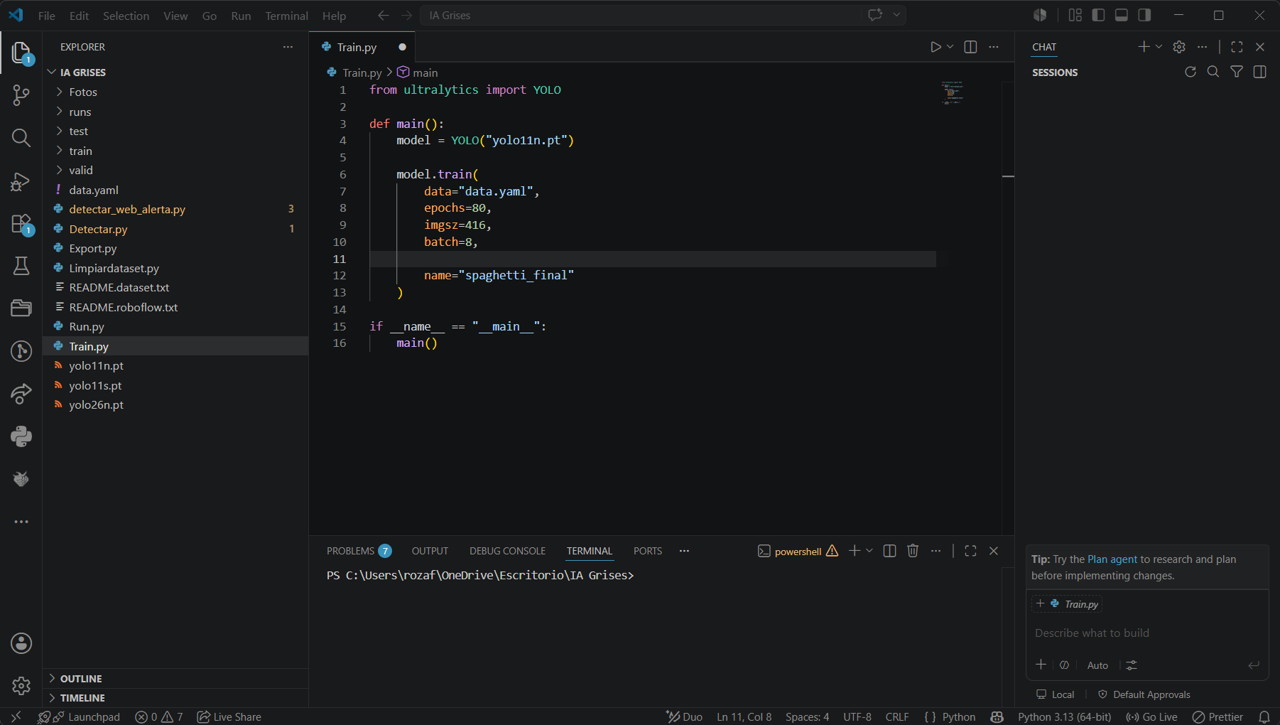
The model was trained with transfer learning, and multiple experiments were performed while
adjusting hyperparameters such as:
Epochs
Image size (imgsz)
Batch size
Confidence threshold
During testing, several augmentations such as mosaic and aggressive transformations generated excessive false positives, so they were reduced or disabled in later experiments. The model performance was evaluated using a confusion matrix, a Precision-Recall curve, and the F1-Score.
Embedded SystemRaspberry Pi 5
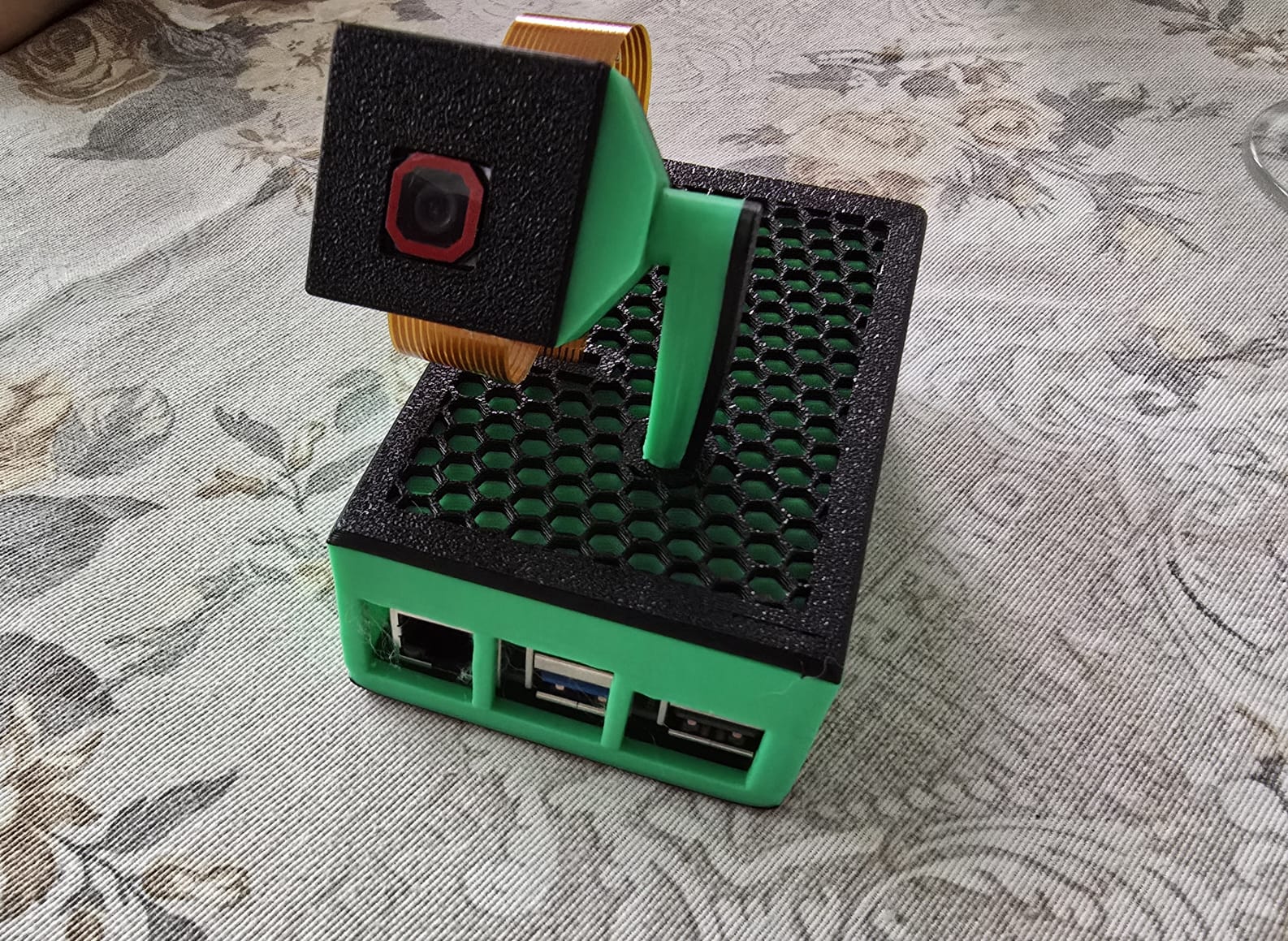
After training, the model was exported and deployed to a Raspberry Pi 5 connected to a camera module through the dedicated camera interface (port J4 / CSI).
The deployment relied on:
Picamera2 — for capturing video from the camera connected to the J4 port
OpenCV — for image processing and grayscale conversion
Ultralytics YOLO — for running the trained vision model
On the Raspberry Pi, the system performs real-time image capture, grayscale conversion, vision
inference, video visualization, notification handling, and web streaming. Running everything
locally eliminates the need for cloud processing and allows the printer to be monitored
continuously without external servers.
Raspberry Pi 5 with the camera module connected to the J4 port, mounted to observe the print bed.
Web Monitoring InterfaceHTTP Streaming
A web-based monitoring interface was developed using Flask and HTTP video streaming over the local network.
This interface allows the user to:
Watch the printer remotely in real time
View the vision detections live
Monitor printer status remotely
Access the system from any device on the network
The interface displays the processed video feed directly from the Raspberry Pi, including detection overlays and status messages generated by the vision system.
This feature transforms the Raspberry Pi into a lightweight standalone monitoring server for additive manufacturing supervision.
Remote AlertsMQTT + NTFY + BLE LED
To improve usability, a remote alert system was integrated into the monitoring platform using
MQTT for event communication and ntfy for push notifications.
When the vision system detects a spaghetti failure continuously for 3 seconds, the Raspberry Pi automatically sends a notification. Requiring 3 continuous seconds of detection before triggering the alert prevents momentary false detections from generating unnecessary notifications.
This system allows users to receive immediate alerts on their smartphones or computers without constantly supervising the printer physically.
A cooldown system was also implemented to prevent notification spam caused by temporary false detections.
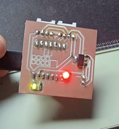
Physical Alert — LED on a XIAO over Bluetooth
On top of the phone/computer notifications, the system also gives a physical warning:
when a failure is detected, the Raspberry Pi lights up an LED. The LED is not wired
directly to the Pi — it is driven by a Seeed Studio XIAO microcontroller that is
connected to the Raspberry Pi over Bluetooth (BLE).
The flow is: the moment the vision model confirms a spaghetti failure, the Raspberry Pi sends a
Bluetooth message to the XIAO, and the XIAO turns the LED on. This gives an immediate, at-a-glance
signal right next to the printer — anyone in the room can see the LED is on and know a failure was
detected, even without looking at a phone or the web monitor. Using Bluetooth means the XIAO with the
LED can be placed anywhere near the printer without running a cable back to the Pi.
The XIAO with the warning LED: the Raspberry Pi sends a Bluetooth (BLE) message on a detected
failure, and the XIAO turns the LED on.
Initial ResultsFirst Training
The first training runs were not good. They produced:
High false positives
Confusion between visually similar classes
The underlying problems were inconsistent labels, too many categories, and minimal visual
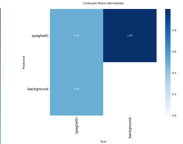
differences between failure types. The normalized confusion matrix from this stage showed the
model failing to separate spaghetti from background reliably.
Initial normalized confusion matrix: the model confused spaghetti with the background.
ResultsModel Improvement
After cleaning and specializing the dataset, the model improved noticeably in:
Precision
Recall
Detection stability
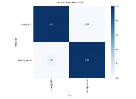
The model began to focus exclusively on disordered filaments and the typical accumulations of a
spaghetti failure, with a significant reduction in false detections. The final normalized
confusion matrix reached 0.94 correct detection for spaghetti and
0.96 for background, a large improvement over the first attempts.
Final normalized confusion matrix: 0.94 for spaghetti and 0.96 for background.
ResultsPerformance on the Pi 5
The final system successfully ran real-time inference directly on the embedded hardware, proving
that YOLOv11n is viable on a Raspberry Pi 5. The grayscale preprocessing helped reduce the
computational load and improve stability while maintaining acceptable detection performance.
The complete system was capable of running, at the same time:
The camera capture
The vision inference
The web page
The alert system
Final ResultSystem in Use
The final system displayed the live, vision-annotated grayscale feed in a browser under the title
"Monitor Inteligente de Impresión 3D", accessible from any device on the local network at the
Raspberry Pi's IP address. While a print is healthy it shows a green "Impresión normal" overlay,
and it switches to a warning when a spaghetti failure is detected.
Web monitor showing the live grayscale feed with the "Impresión normal" detection overlay.
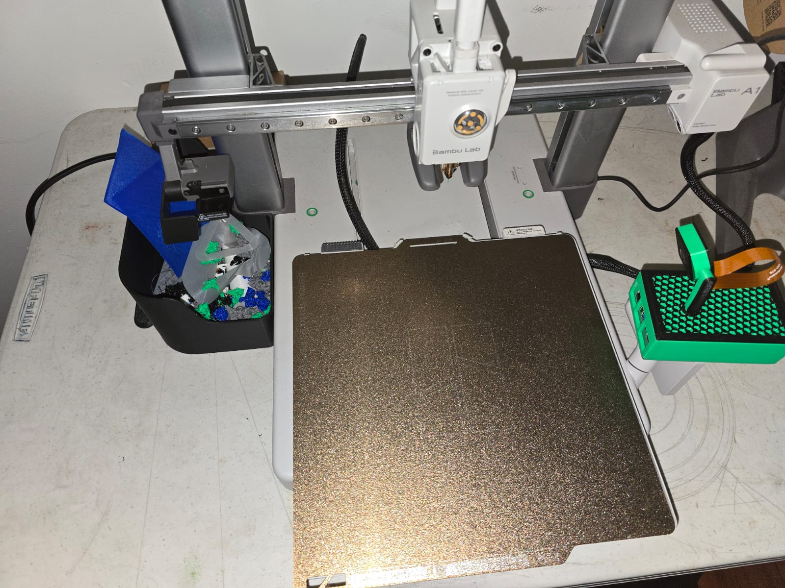
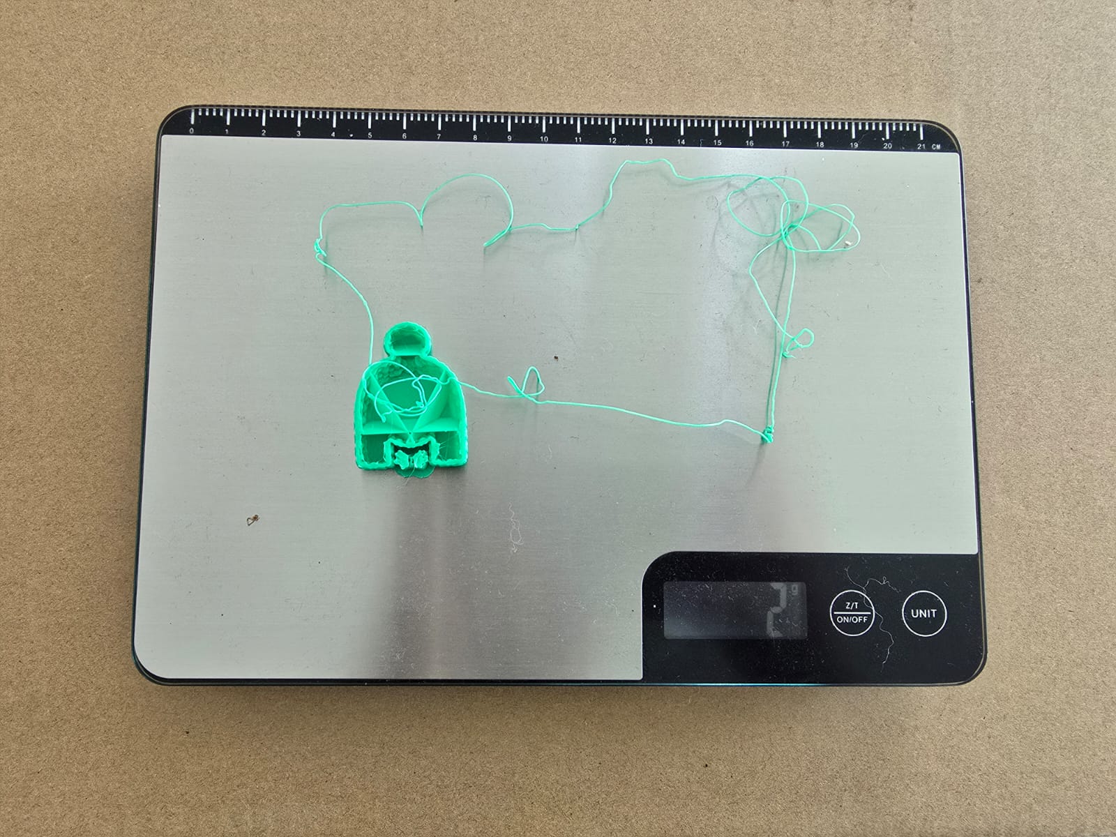
To validate the practical value of the system, a real spaghetti failure was captured and the
wasted material was weighed: an A1-printed model that should have produced a clean ~14 g part
instead generated a tangled mass of filament. This is exactly the kind of waste the system is
designed to catch early.
A failed print versus the intended part, weighed on a scale to show the filament wasted by a detected spaghetti failure.
Technical ConsiderationsEmbedded Vision
Developing this system required balancing detection accuracy with embedded hardware limitations.
Several engineering decisions were necessary, including:
Model selection: choosing YOLOv11n for lightweight inference
Image preprocessing: grayscale conversion to reduce complexity
False positive reduction: simplifying the dataset classes
Embedded optimization: reducing image resolution for real-time execution
Network communication: integrating MQTT and HTTP streaming
Physical alert over BLE: sending the failure event to a XIAO over Bluetooth to drive a warning LED
System stability: preventing repeated false alerts
One of the most interesting aspects of this project was combining computer vision, embedded systems, networking, and manufacturing into a single integrated workflow.
ConclusionsSummary
A functional system for automatic spaghetti-failure detection was achieved using computer vision.
YOLOv11n proved to be a suitable architecture for the Raspberry Pi 5 thanks to its low computational load and inference speed.
Cleaning and specializing the dataset significantly improved the model's performance, reducing false positives and allowing more precise detection.
Grayscale images helped optimize processing without considerably affecting detection capability.
Integrating remote monitoring and automatic alerts increased the practical usefulness of the system, allowing prints to be supervised in real time from any device on the network.
Adding a physical LED warning driven by a XIAO over Bluetooth gave an immediate, at-a-glance signal right next to the printer.
The project demonstrates that computer vision can be applied successfully to 3D printing.
Future WorkNext Steps
Expand the dataset with real images from different printers and lighting conditions.
Improve the model to further reduce false positives and increase detection accuracy.
Integrate automatic printer control to stop the print when a critical failure is detected.
Implement image storage and a historical log of detected events.
Expand the system to detect other 3D printing defects such as poor bed adhesion, warping, under-extrusion and layer shifting.
Develop a more complete web interface for remote monitoring and administration.
DemonstrationSystem in Action
The following video shows the system working in real time: the computer-vision model detects the spaghetti failure, and after 3 continuous seconds of detection it automatically sends the alert.
System Demonstration
Demonstration of the system in action: the vision model detects a spaghetti failure, and after 1 second it sends an alert and turns on the warning LED.
Reflection
This project allowed me to explore how computer vision can be integrated into real manufacturing environments using affordable hardware.
I learned that training a vision model involves much more than simply selecting a model. Dataset quality, class consistency, preprocessing, and real-world testing all strongly influence system performance.
One of the most valuable lessons was understanding the challenges of deploying computer-vision models on embedded hardware, where computational resources are limited and optimization becomes essential.
Overall, this project demonstrated how computer vision can improve automation and monitoring processes in digital fabrication and additive manufacturing.
Assignment RequirementsWhat this page demonstrates
This week is a wildcard: I chose a fabrication process that was not covered in
the other weeks — computer-controlled machine embroidery. This page documents how
my work meets each of the individual requirements and learning outcomes for the week:
Requirement
Where it is covered
Design and produce an artifact with a digital fabrication process not covered in another assignment
For the wildcard week I wanted a process that combines vector design with a
computer-controlled machine, but that was different from the CNC, laser and 3D
printing work from earlier weeks. Machine embroidery fit perfectly: the design is prepared as
vectors on the computer, converted into stitch paths, and then a digital
embroidery machine sews it automatically thread by thread.
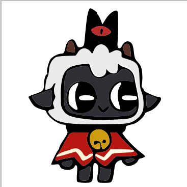
As the subject I chose "The Lamb", the main character of the video game
Cult of the Lamb. It has clearly separated color regions (white wool, dark body, red
cape, yellow bell, red eye), which makes it a good test case for splitting an image into
individually-stitched objects.
Reference art of The Lamb used as the source image.
Design WorkflowInkscape + Ink/Stitch
Why Inkscape and Ink/Stitch?
I used Inkscape with the Ink/Stitch extension because it is a
free, open-source toolchain that goes all the way from a normal image to a machine-ready
embroidery file (.PES for Brother). Ink/Stitch converts each vector object into
stitches, lets me choose the fill type, order the objects, add machine commands, and simulate the
result before sewing.
The overall workflow is raster → vector → stitch → machine. The steps below
follow that path from setting up the document to exporting the embroidery file.
Step-by-step design (Click to view)
Step 1 — Set up the document size
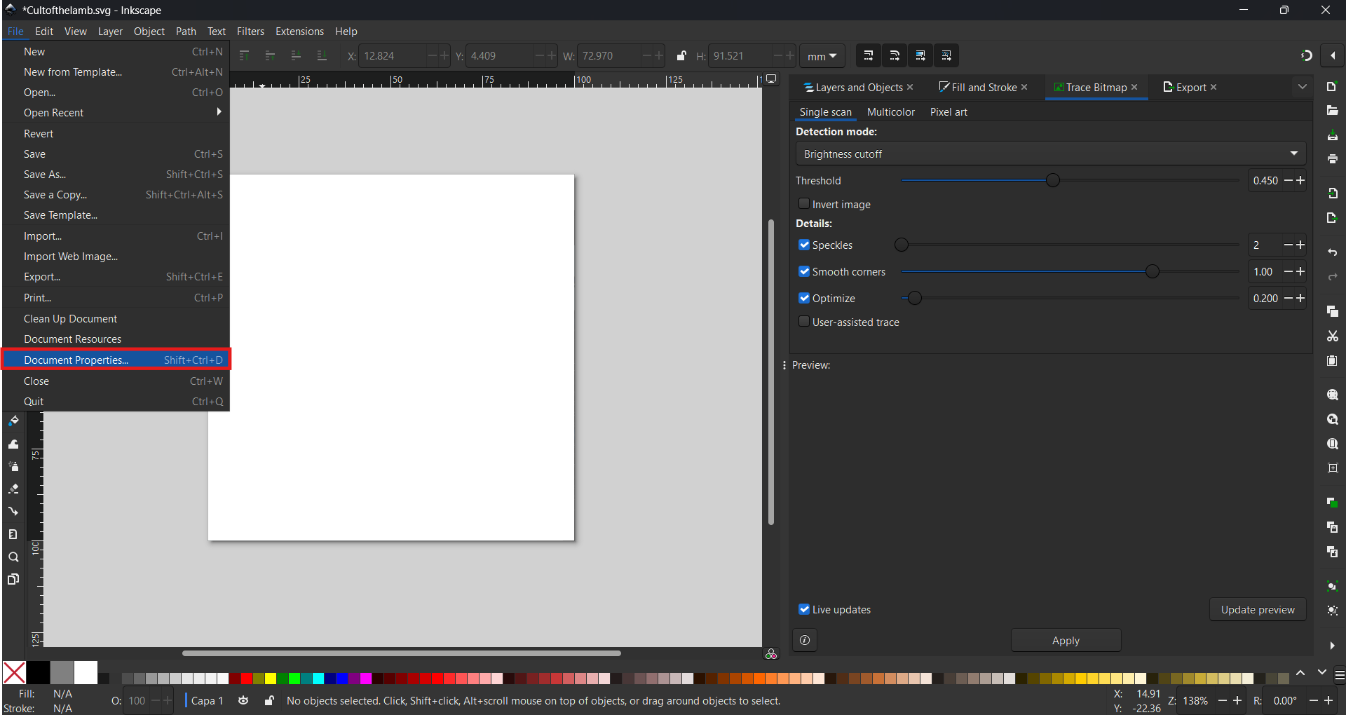
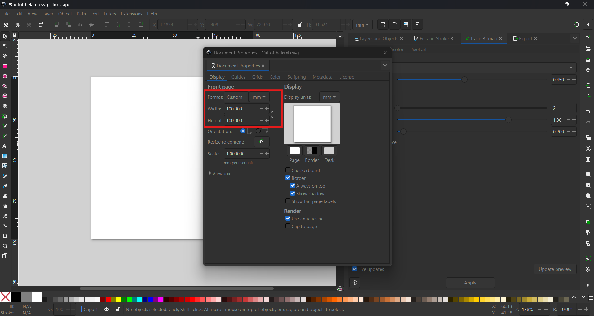
First I opened File → Document Properties and set the front page to a
Custom format of 100 × 100 mm. Working in millimetres from
the start keeps the design at the real size the machine will sew, so the embroidery does not end
up larger than the hoop.
File → Document Properties (Shift+Ctrl+D).Custom page format set to 100 × 100 mm.
Step 2 — Import the reference image
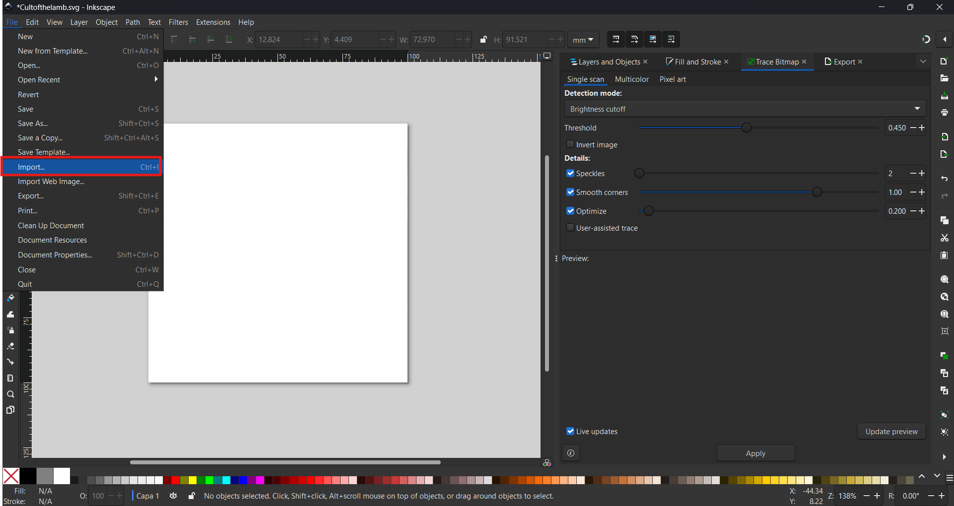
With File → Import I brought the raster PNG of The Lamb into the canvas. This
bitmap is only a reference — it cannot be embroidered directly, because the machine needs
vector paths, not pixels.
File → Import (Ctrl+I) to load the reference image.
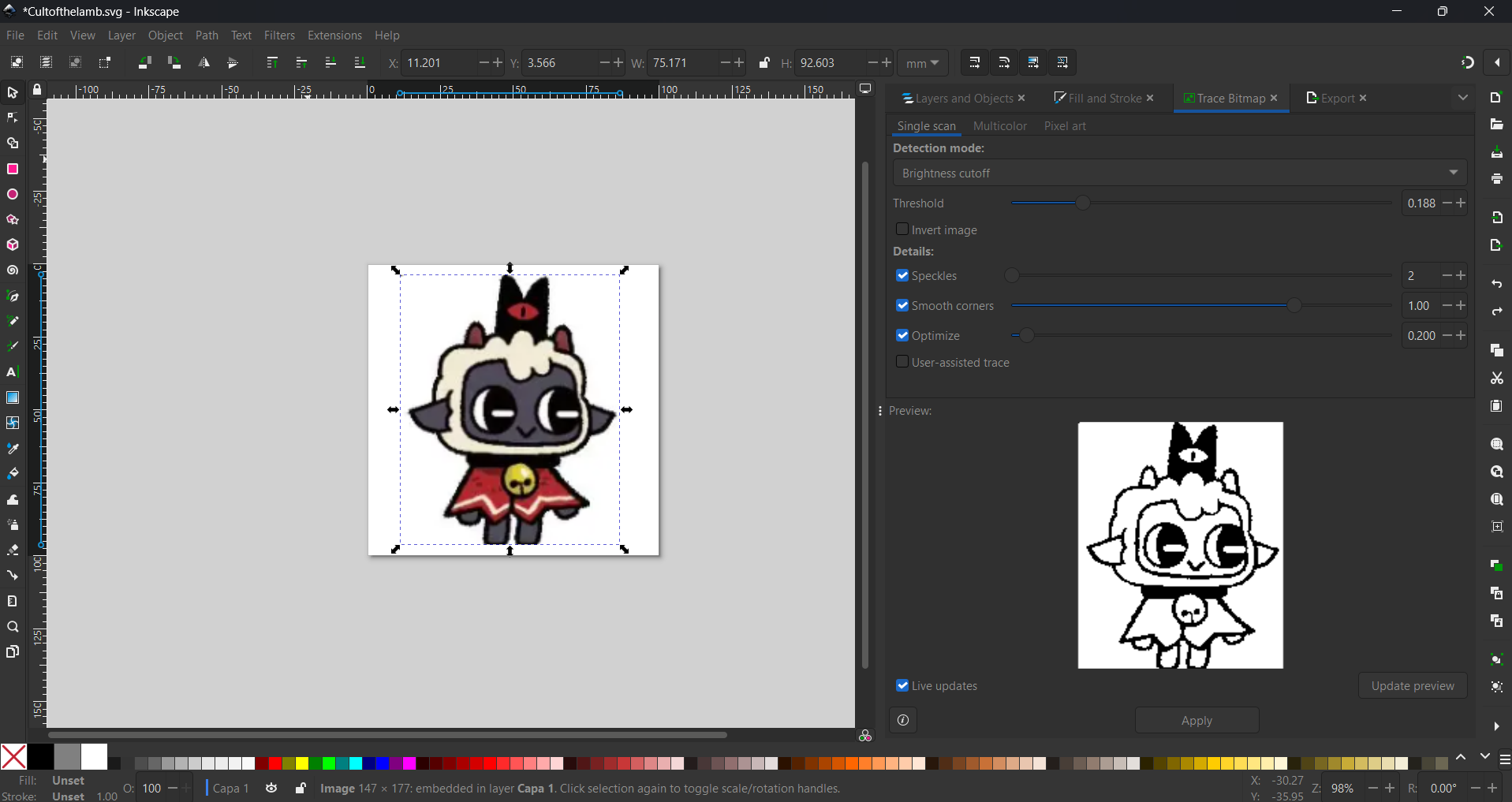
Step 3 — Trace the bitmap into vectors
I opened Path → Trace Bitmap and used Single scan with the
Brightness cutoff detection mode. The Threshold slider
controls how much of the image becomes black; I tuned it (around 0.188–0.450) while watching the
live Preview until the outline of the character was clean. The
Speckles, Smooth corners and Optimize options
remove noise and simplify the resulting path.
Trace Bitmap → Single scan with a live preview of the vectorized outline.
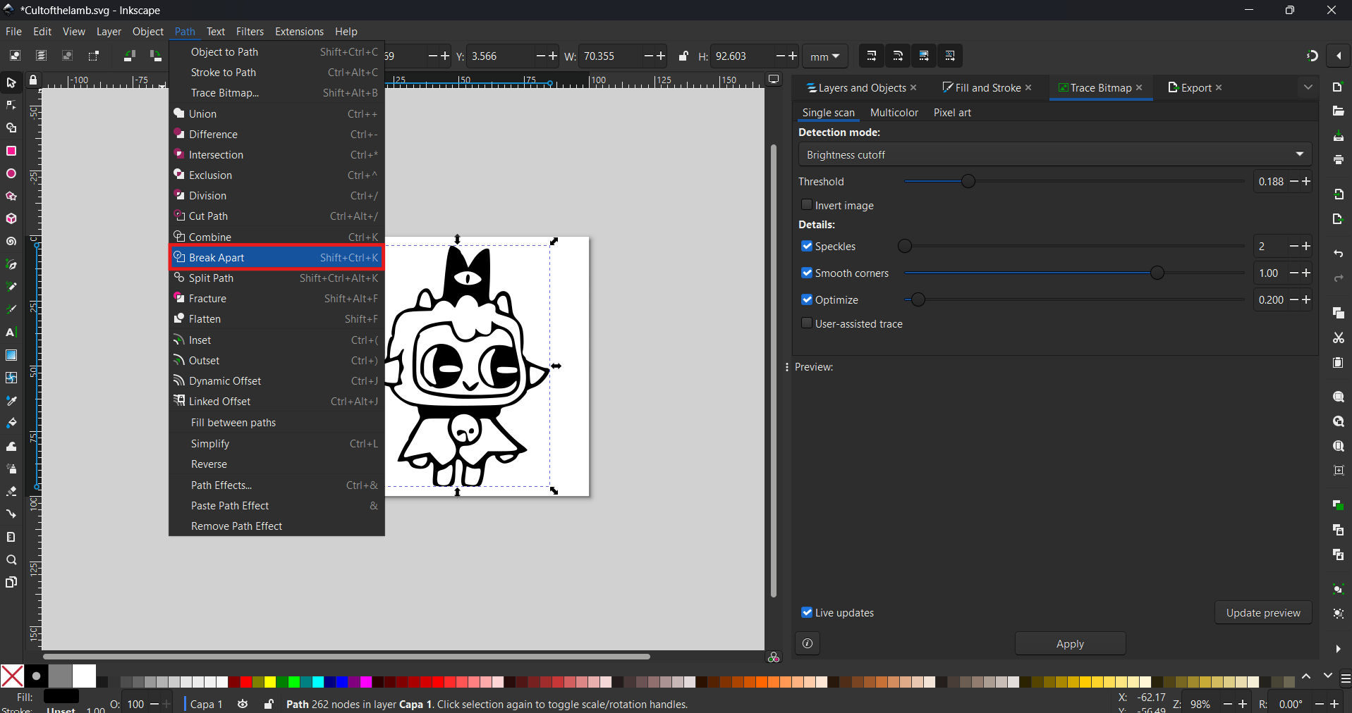
Step 4 — Break the trace into separate objects
The trace comes out as a single compound path. Using Path → Break Apart
(Shift+Ctrl+K) I split it into many independent sub-paths, so each region of the character
becomes its own object that can be colored and stitched separately.
Path → Break Apart to separate the traced compound path.
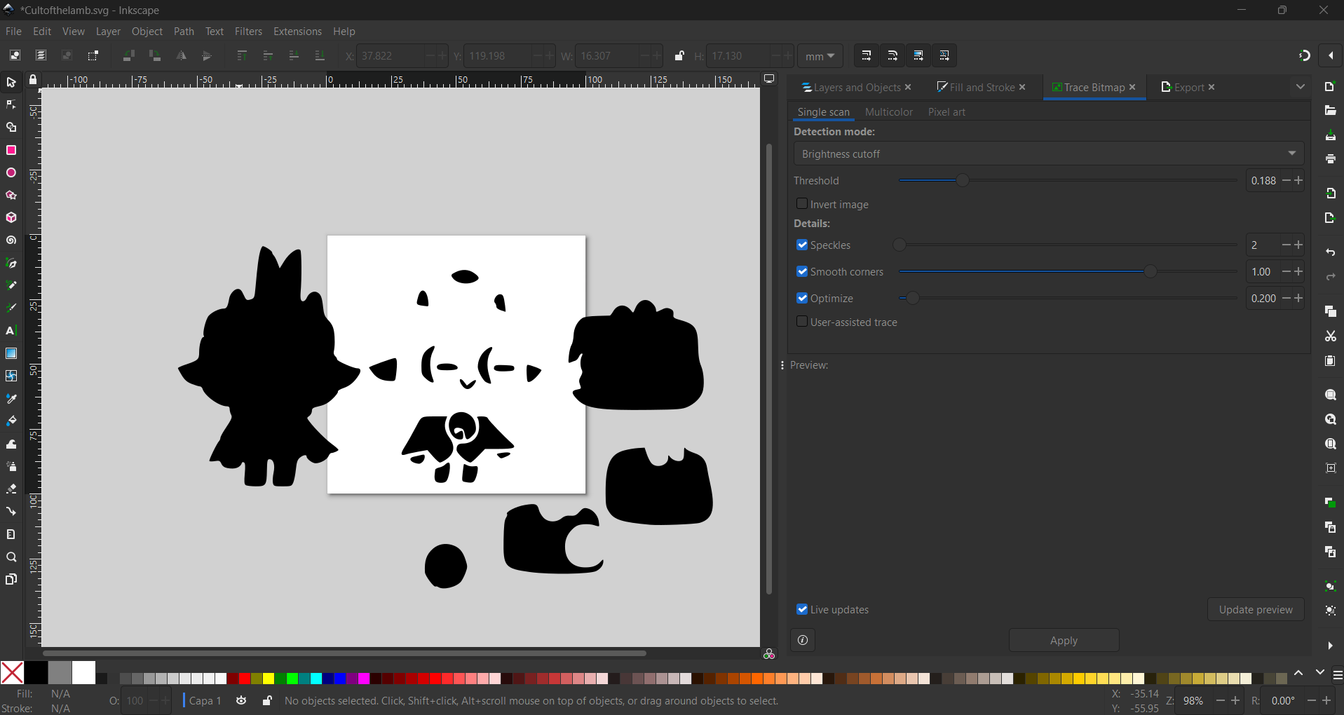
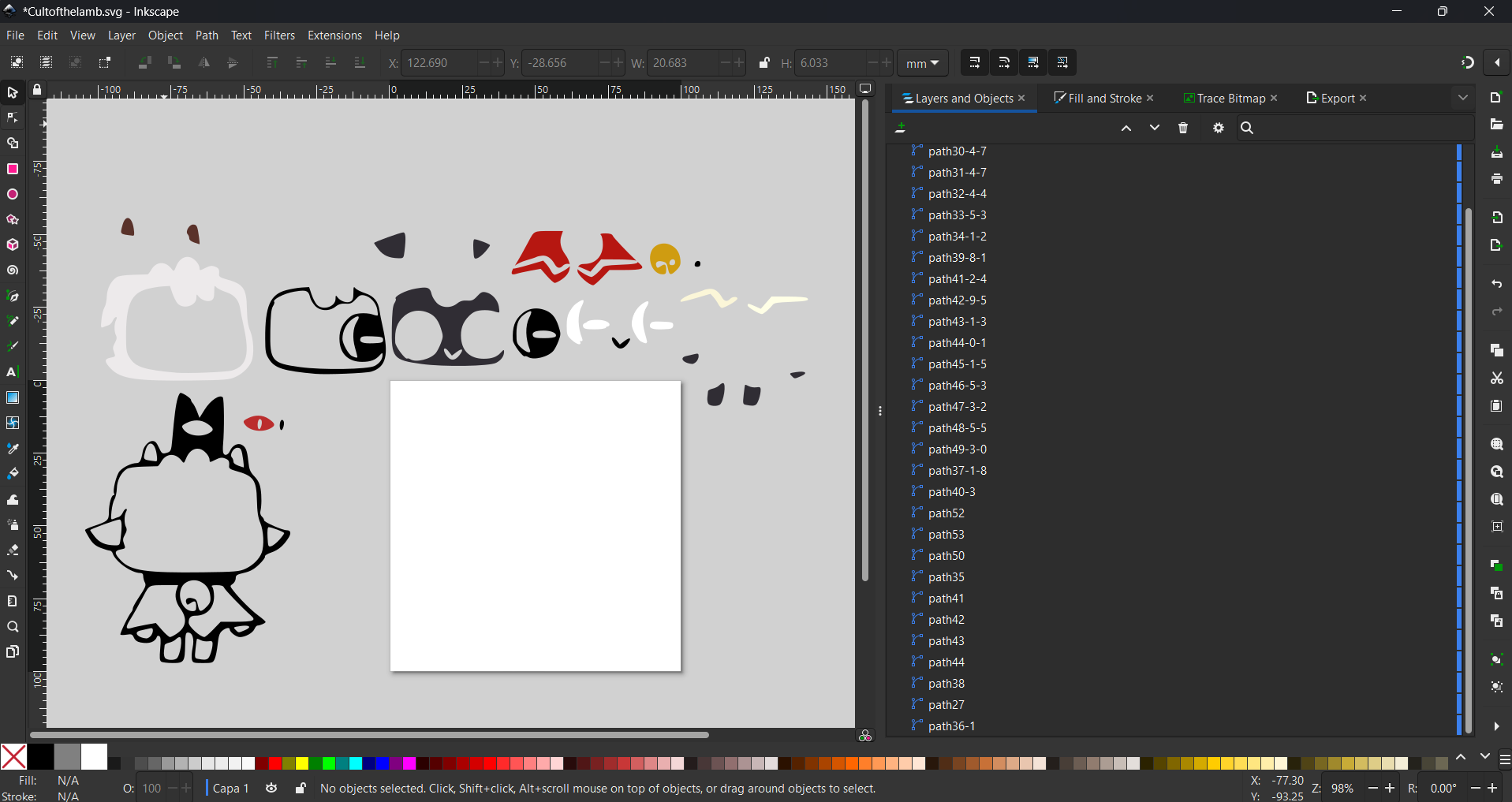
After breaking apart I also used Break Path where I needed to split individual
outlines further, ending up with all the pieces (wool, body, cape, eyes, bell…) laid out as
separate objects.
The character decomposed into individual, separately-editable pieces.
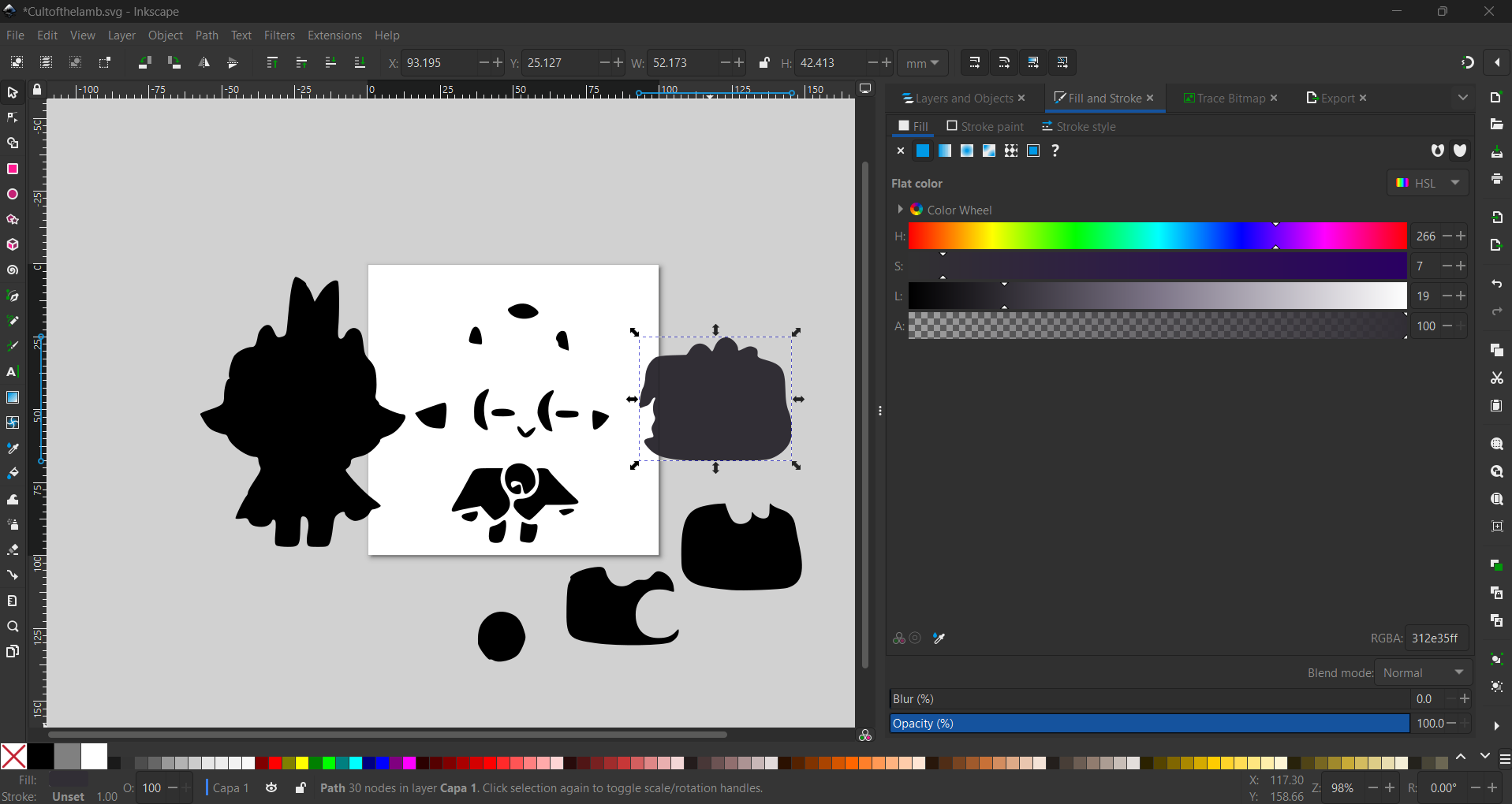
Step 5 — Assign a flat color to each object
Using the Fill and Stroke dialog I gave every object a single
flat color matching the original art (for example the dark body was set to
RGBA 312e35ff). In embroidery, one flat color region equals one thread color, so
keeping the palette clean directly controls how many thread changes the machine will need.
Fill and Stroke → flat color applied to each separated object.
Step 6 — Clean overlaps with Difference
Where two shapes overlapped, the thread would otherwise be stitched twice, wasting thread and
building up bulk. I used Path → Difference to subtract the top shape from the
one below, so each area of fabric is only covered by a single object.
Path → Difference removes the overlapping region between two objects.Result: the underlying shape now has the overlap cut out.
Stitch DesignInk/Stitch Params
Turning shapes into stitches
With the objects cleaned up, the next stage is telling Ink/Stitch how to fill each one.
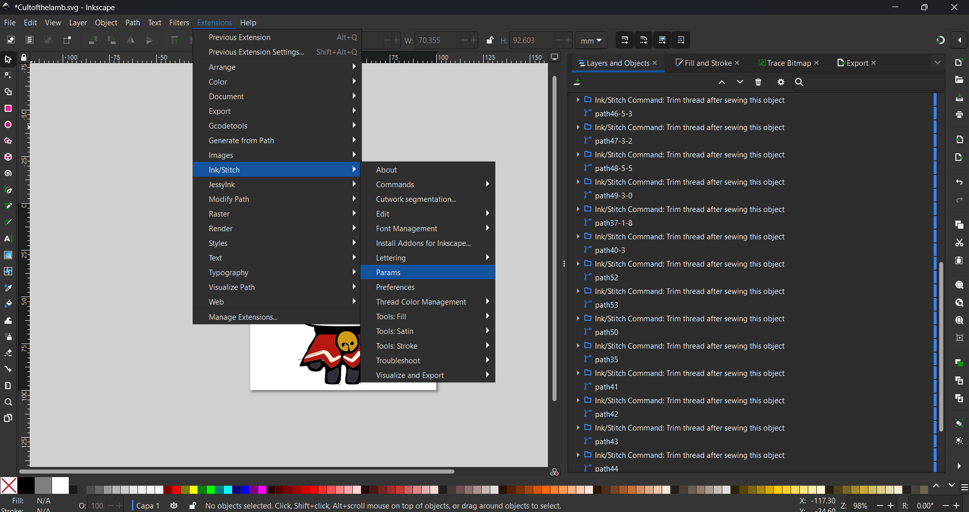
This is done through Extensions → Ink/Stitch → Params, where every object gets a
stitch type and its parameters (angle, density, underlay…). Choosing the right fill for each shape
is the core of "digitizing" an embroidery design.
Extensions → Ink/Stitch → Params to set the stitch type per object.
Fill types I compared (Click to view)
I tested three fill types on the shapes to see how each one covers an area. The direction and
pattern of the stitches change both the look and how the thread behaves on the fabric.
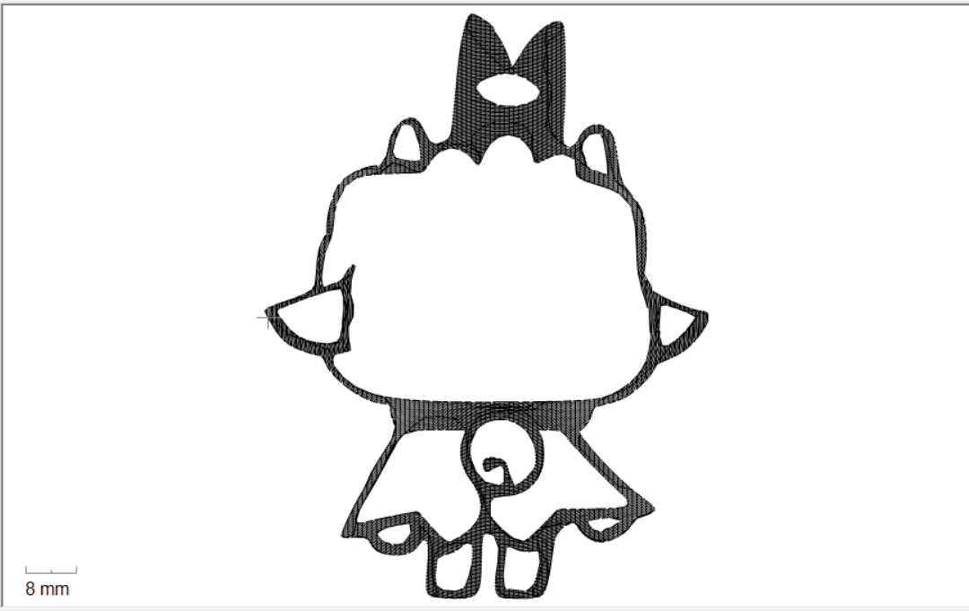
Auto fill
Auto fill lays down parallel rows of stitching and automatically routes the
path across the whole shape, breaking it up and travelling between sections as needed. It is the
general-purpose fill and the one I used for most of the body.
Auto fill: parallel rows automatically routed across the shape.
Circular fill
Circular fill spirals the stitches around a center point instead of running
straight rows. It gives a rounded, concentric texture that suits circular or organic regions.
Circular fill: stitches spiral around a center point.
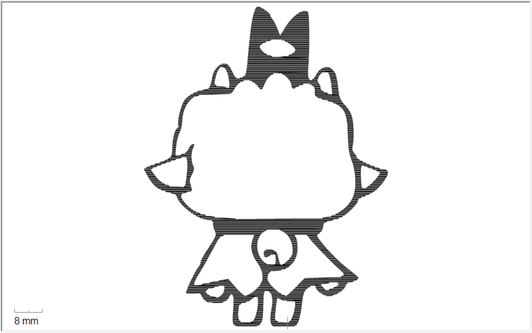
Legacy fill
Legacy fill is the older fill algorithm. It produces straight rows like auto
fill but with simpler, less optimized routing, which can leave more visible travel stitches. I
used it as a comparison to understand why auto fill is usually the better default.
Legacy fill: straight rows with simpler routing.
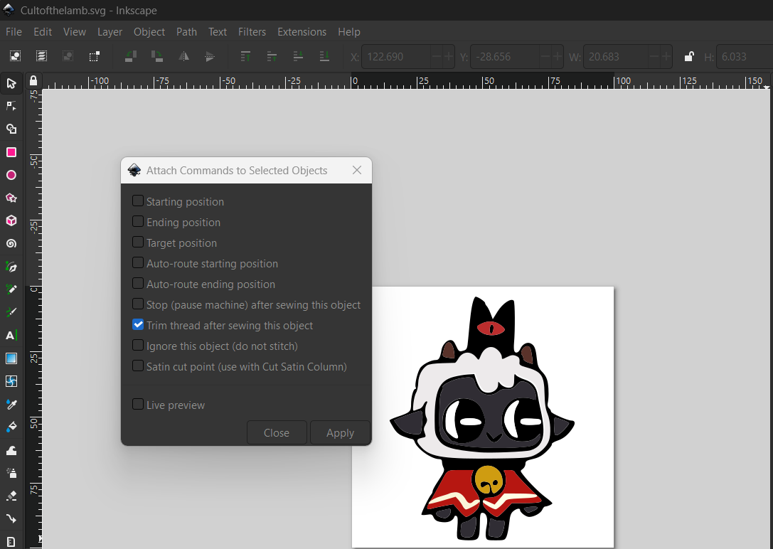
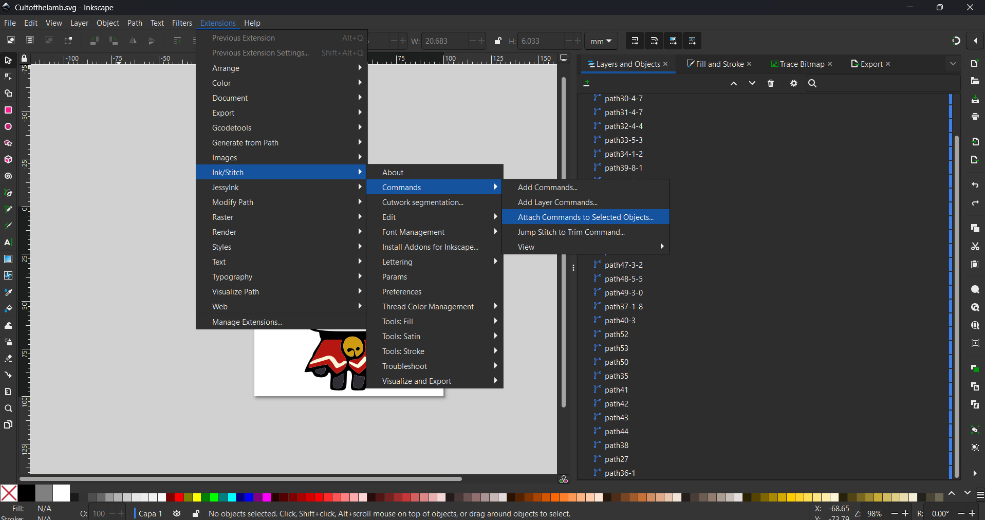
Trim commands between objects
Because the design jumps between separated regions, I attached a Trim thread after sewing
this object command to the objects. This is done with Extensions → Ink/Stitch →
Commands → Attach Commands to Selected Objects and ticking Trim thread after sewing
this object. It tells the machine to cut the thread after each piece instead of leaving long
jump threads across the design.
Each object carries an Ink/Stitch "Trim thread after sewing" command.Attach Commands → "Trim thread after sewing this object" checked.
SimulationInk/Stitch Simulator
Simulating before sewing
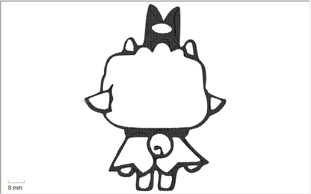
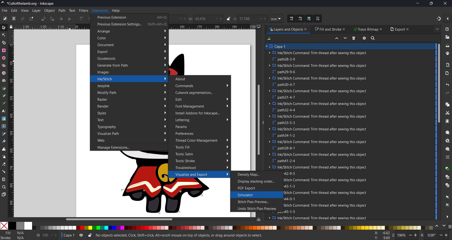
Before touching the machine I ran the Simulator from Extensions →
Ink/Stitch → Visualize and Export → Simulator. It plays back the whole embroidery stitch
by stitch, in the exact order and colors the machine will use, so I could check the stitching
order, the trims and any obvious problems without wasting thread or fabric.
Extensions → Ink/Stitch → Visualize and Export → Simulator.
Simulator playback of the full stitch order for the design.
Embroidery MachineBrother Innov-is NS1850L
Sewing on the Brother Innov-is NS1850L
Once the design was exported as a .PES file, I moved it to the
Brother Innov-is NS1850L embroidery machine. The finished design measures about
92.6 × 70.2 mm, which fits the machine's embroidery hoop. The steps below follow
how I loaded and started the job on the machine.
Machine setup (Click to view)
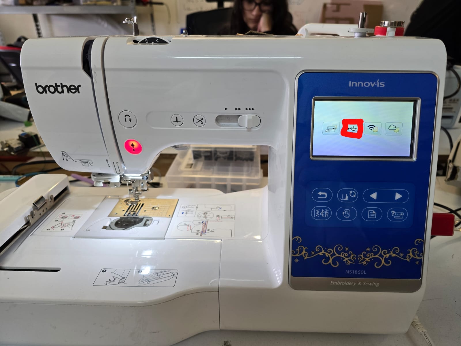
Step 1 — Load the file from USB
I inserted the USB drive with the .PES file and selected the USB
source on the machine's touch screen to browse the embroidery files.
Choosing the USB source on the NS1850L touch screen.
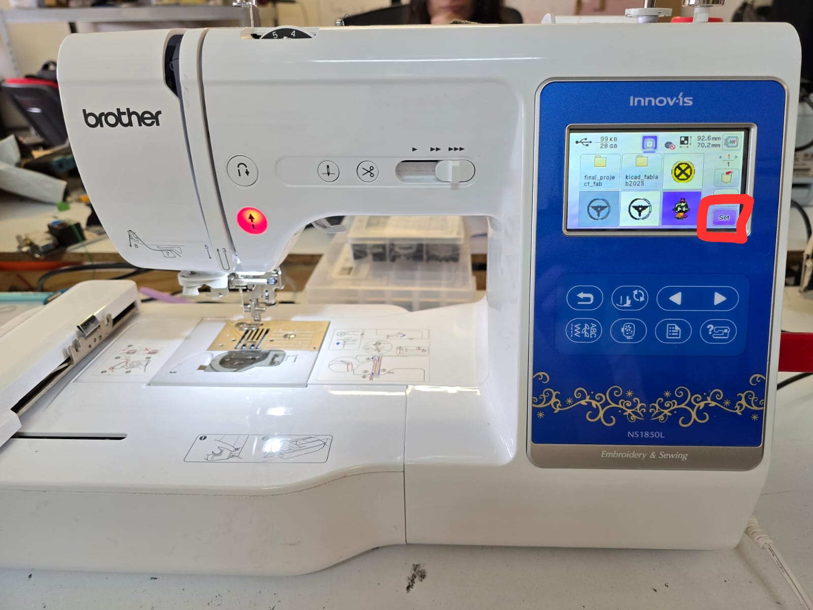
Step 2 — Select the design and press Set
I opened the project folder, selected the Lamb design and pressed Set to load
it into the embroidery workspace. The screen shows the design preview along with its final size
(92.6 × 70.2 mm).
Design selected on the USB browser; Set confirms the choice.
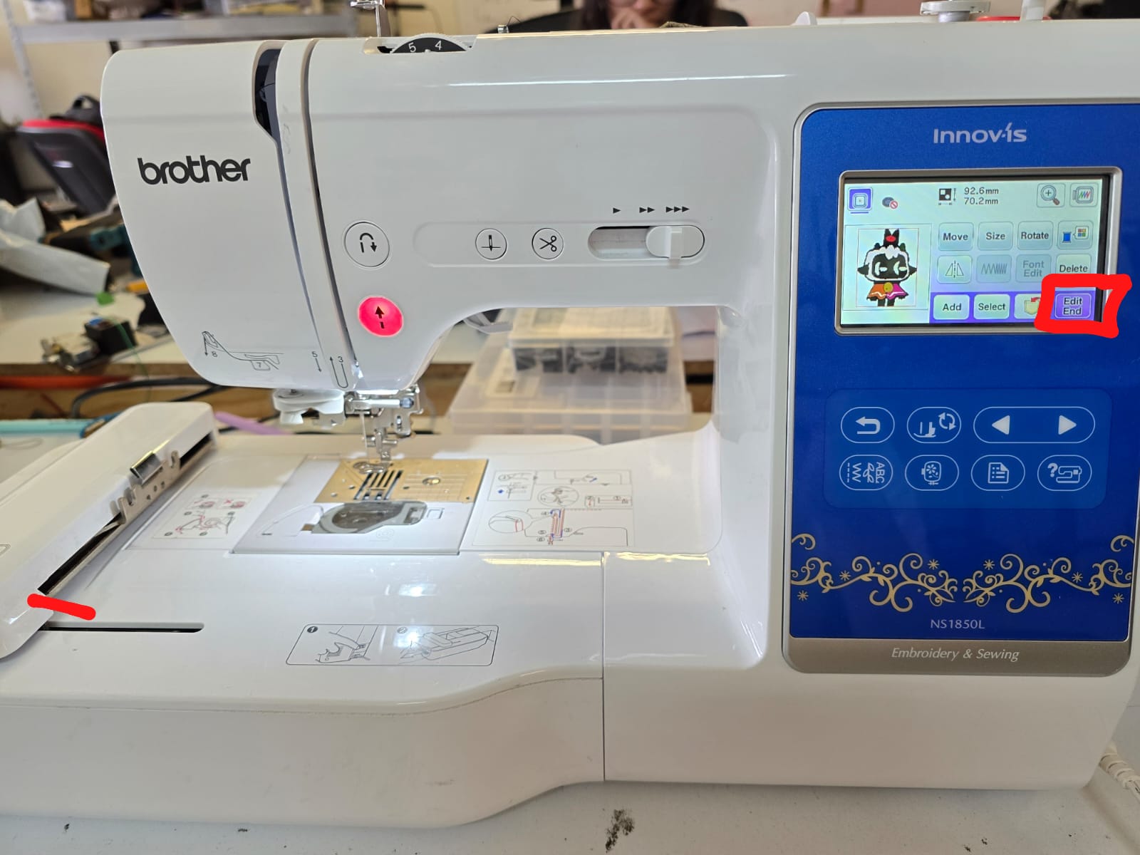
Step 3 — Edit and start embroidering
On the edit screen I could Move, Size and Rotate
the design to position it on the hoop, then pressed Edit End to go to the sewing
screen and start. The machine then sews each color region, pausing for thread changes and
trimming between objects as programmed.
Edit screen: position the design, then Edit End to begin.
Embroidering
The videos below show the machine actually sewing the design and a thread color change between
regions.
The machine stitching a fill region of the design.
Another region being embroidered.
Changing the thread color between two objects.
ResultFinished patch
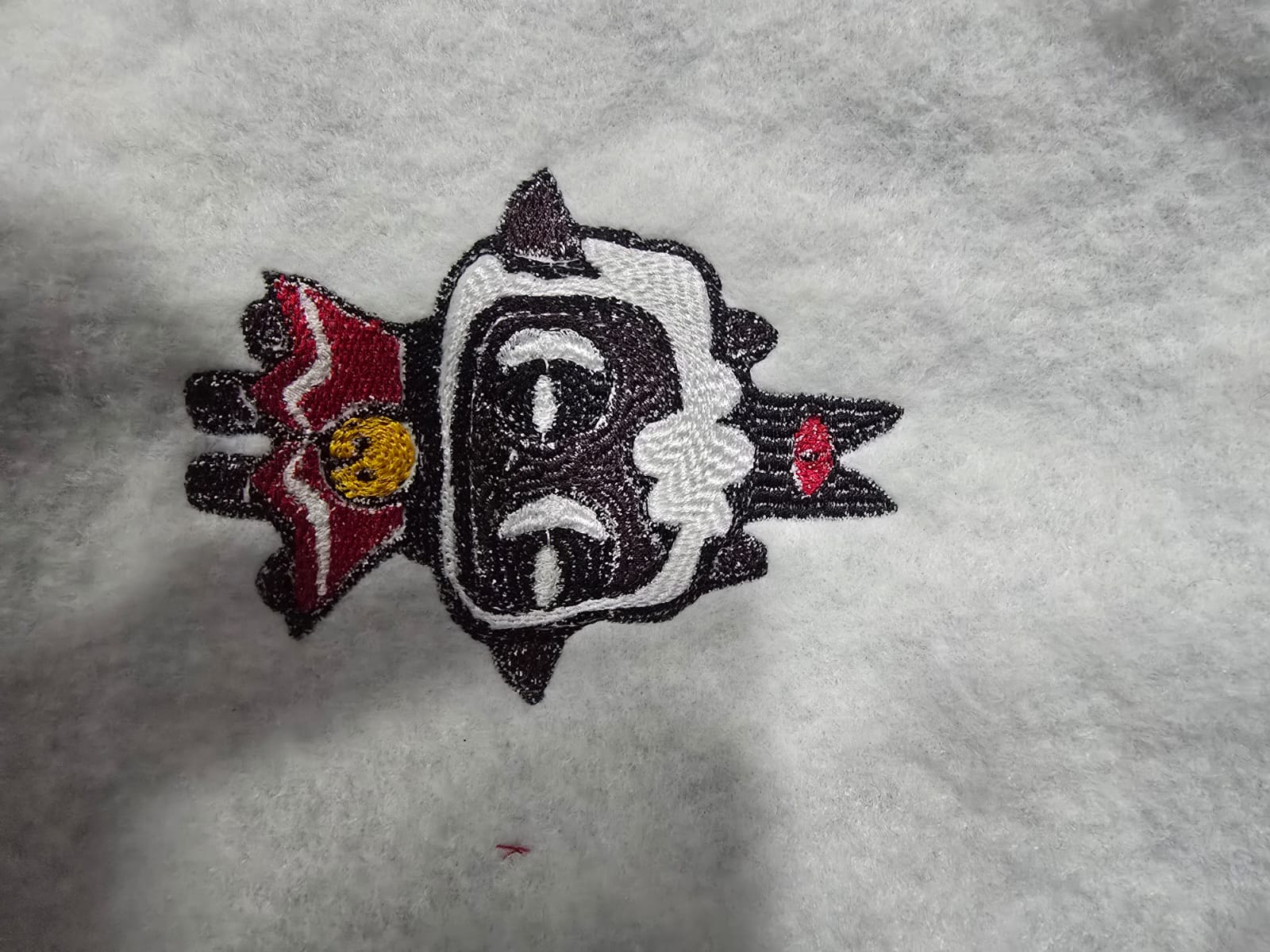
Final embroidered result
The finished embroidery reproduces The Lamb with its separate color regions: the white wool, the
dark body and horns, the red cape, the yellow bell and the red eye. Some fine details shifted
slightly compared to the digital preview — a normal effect of thread density and fabric pull —
which is exactly the kind of design-rule lesson this wildcard week was meant to teach.
The finished machine-embroidered Lamb.The finished path.
Machine EmbroideryAdvantages & Limitations
Advantages and limitations of machine embroidery
Digitizing and sewing this patch made the design rules of embroidery very concrete. Here is what I
learned firsthand.
Advantages
Repeatable and automatic: once the file is digitized, the machine sews the same design consistently every time, with automatic thread trims.
Durable result: the thread patch is tough, washable and looks far more professional than a printed transfer.
Vector-driven: the design starts from the same kind of vector workflow I already use, so it fits naturally with the rest of my Fab Academy toolchain.
Free software path: Inkscape + Ink/Stitch export directly to the machine format at no cost.
Rich texture: different fill types and stitch angles give a tactile, physical quality that flat fabrication can't.
Limitations
Small detail is hard: very thin lines and tiny features (like the eye) don't resolve cleanly — the needle and thread have a minimum feature size well above a laser or printer.
Overlap and density matter: overlapping shapes must be cut with Difference, and too-dense fills pucker the fabric or break the thread.
Stitch order and trims: a bad object order means long jump threads and many manual thread changes; it must be planned deliberately.
Fabric pull / distortion: the thread tension distorts the shapes slightly, so the sewn result never matches the digital preview exactly.
Color = thread change: every color is a manual thread swap, so a busy palette makes the job much slower.
The takeaway is that embroidery rewards simple, bold, well-separated shapes with a
small palette — quite different from the fine detail a laser or 3D printer can hold.
Final Project Impact
This wildcard week broadened the set of fabrication processes I can draw on for personalization and
branding.
Machine embroidery gives me a way to add durable, professional branding or labels to fabric parts.
The raster → vector → stitch workflow reinforces the vector discipline I use across the whole project.
Understanding embroidery design rules (feature size, overlaps, color = thread change) helps me choose the right process for each future artifact.