Integration of the mechanical, electronic, sensing, control and monitoring systems into the final PrintVault Pro prototype.
Project OverviewSystem Integration
During this week all the individual developments completed throughout Fab Academy were integrated into a single functional system. The objective was to combine mechanical design, electronics production, embedded programming, interface development, sensing, and output devices into the final PrintVault Pro prototype.
PrintVault Pro is a controlled environment designed to improve the reliability of 3D printing by maintaining stable environmental conditions. The system continuously monitors temperature and humidity while controlling internal heating and ventilation.
This week represented the transition from isolated subsystems to a complete product capable of operating as a single integrated machine.
System ArchitectureConcept Design
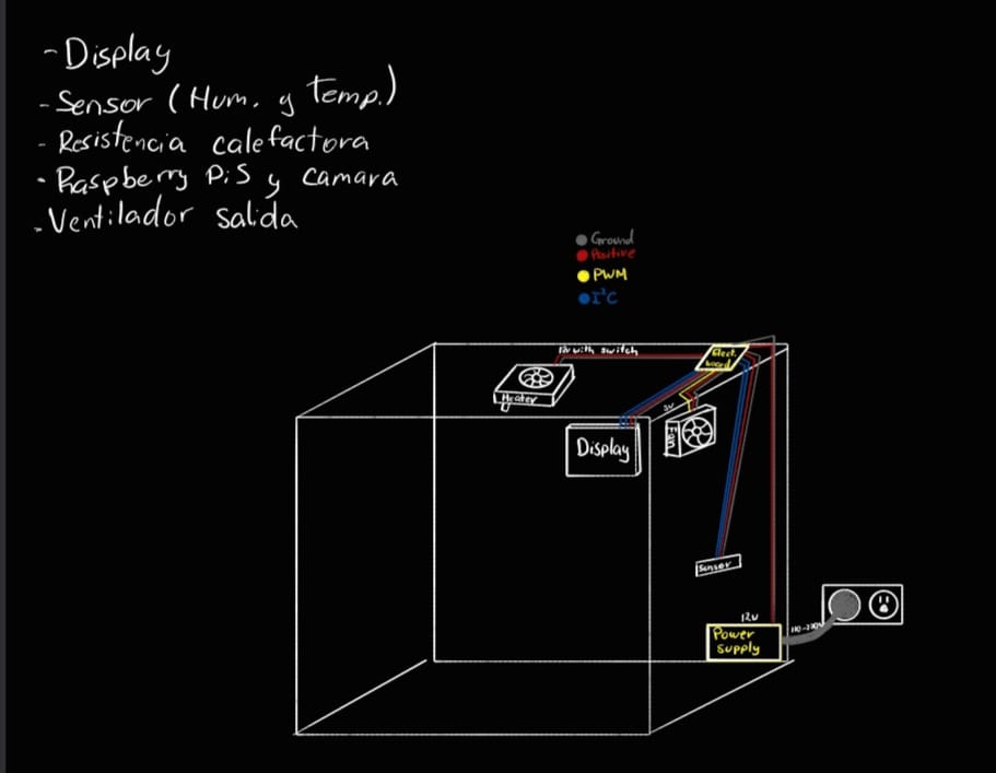
Before beginning assembly, a complete system architecture was developed to define the relationship between all hardware components. The enclosure contains sensing, processing, visualization, heating, ventilation and monitoring systems connected to a central controller board.
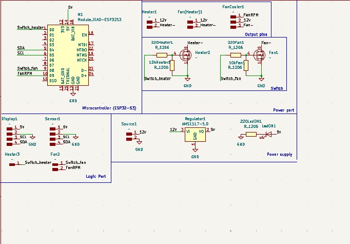
The architecture was designed around a custom PCB developed during the Electronics Design and Electronics Production assignments. This board acts as the central hub that communicates with sensors and output devices.
The final enclosure integrates multiple subsystems that were individually developed throughout the Fab Academy process.
Subsystem
Function
Related Week
Custom PCB
Central electronic controller
Weeks 6 & 8
SHT31 Sensor
Temperature and humidity measurement
Week 9
Cooling Fan
Air extraction and temperature regulation
Weeks 9 & 10
OLED Display
Local system monitoring
Week 11
Heater
Temperature increase inside enclosure
Final Project
Raspberry Pi 5
Image processing and remote monitoring
Final Project
Camera Module
Live visualization of printing process
Final Project
Qt Interface
Remote control dashboard
Week 14
Mechanical IntegrationEnclosure Structure
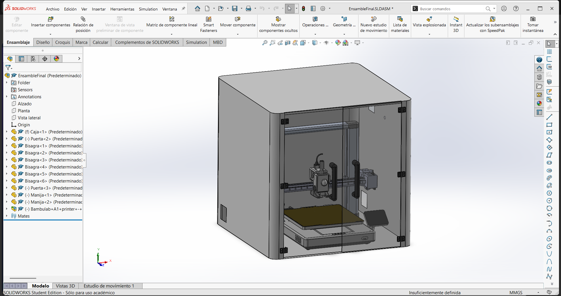
The enclosure structure was designed to provide a thermally controlled environment while maintaining visibility of the printing process.
The body of the enclosure was designed using galvanized steel panels due to their rigidity, durability and resistance to elevated temperatures.
According to the design sketch, the enclosure consists of:
Galvanized steel body panels
Galvanized steel top cover
Galvanized steel bottom panel
Two transparent acrylic doors
Acrylic doors were selected to allow visual inspection of the printer while maintaining thermal isolation.
The enclosure dimensions were established around the size of the 3D printer and future electronic components while maintaining sufficient internal airflow.
The custom PCB serves as the central electronic controller for the entire system. All sensors, displays and actuators are connected directly to this board.
The board integrates:
XIAO ESP32-S3 microcontroller
SHT31 temperature and humidity sensor
OLED display
Fan and heater control outputs (MOSFET drivers)
Power regulation circuitry
User input buttons
This centralized architecture simplifies wiring and reduces the number of independent modules required inside the enclosure.
PCB Housing & WiringIntegration Decisions
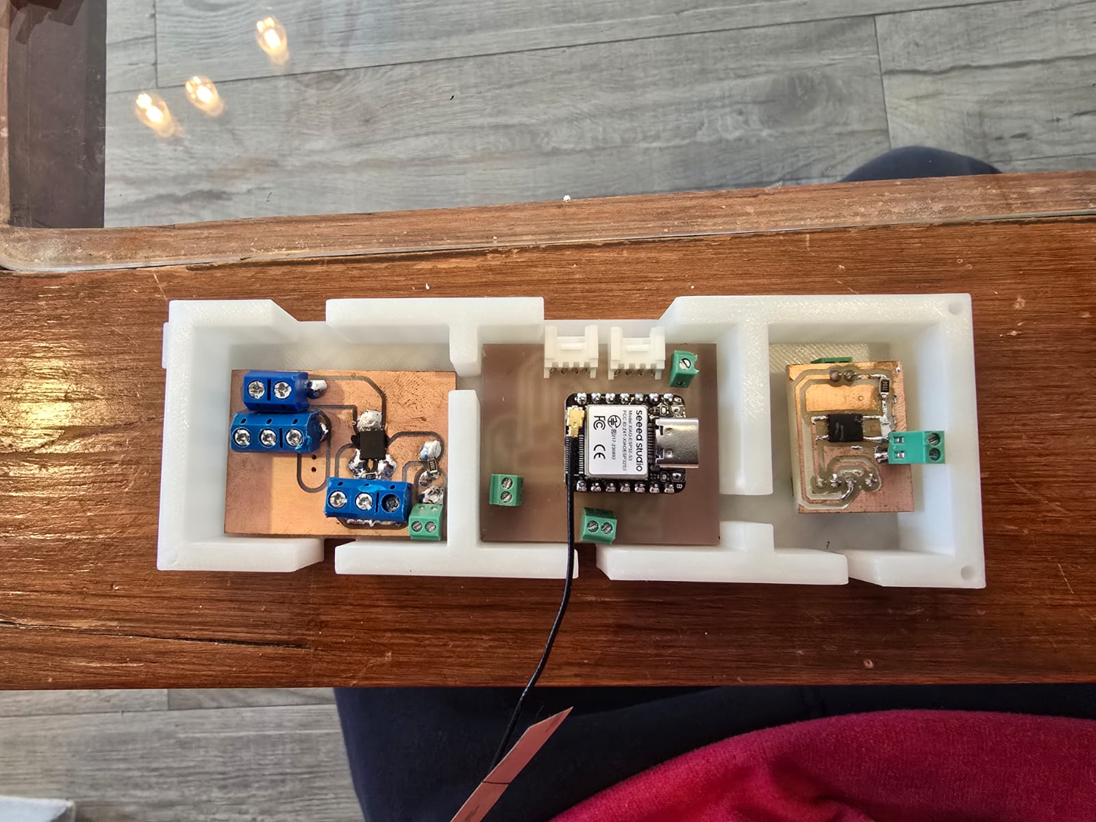
Housing the three PCBs
The electronics of PrintVault Pro are split across three separate PCBs. To keep them
organized and protected, all three boards were mounted together inside a single 3D-printed
box. Grouping them in one enclosure keeps the electronics compartment tidy, protects the
boards from dust and accidental contact, and makes the whole electronics module easy to remove or
service as one unit instead of three loose boards.
Initial wiring idea
My first plan was to place the PCB box on top of the enclosure. On paper this kept
the boards accessible, but when I started routing the connections I realized the
wiring would be spread out and very visible: cables coming from the sensor, the fan,
the heater and the display would all have to travel up to the top of the enclosure, crossing the front
and the sides. The result looked messy and exposed the wiring exactly where the user looks at the
machine.
Final wiring solution
To fix this, I moved the PCB box to the back of the enclosure. Placing the boards
behind the machine means the cabling runs along the rear panel instead of across the front, so
the wiring is hidden from the front view and the machine looks much cleaner. The
connections to each component became shorter and more direct, and the front of the enclosure now shows
only the doors and the print, with no visible cable clutter.
First thought of placing the wiring and PCB box on top of the enclosure, which would have made the wiring visible from the front.
The three PCBs housed in a single 3D-printed box.
Environmental MonitoringInput Devices
Environmental conditions are continuously monitored using an SHT31 digital sensor.
The sensor provides:
Temperature measurements
Relative humidity measurements
Data is transmitted through the I²C communication protocol to the XIAO ESP32-S3 controller.
The measured values are displayed locally on the OLED screen and can also be transmitted to the remote monitoring interface.
Environmental ControlOutput Devices
Two main actuators are responsible for controlling the internal environment:
Heating element
Exhaust fan
The heater increases the internal temperature when necessary, while the fan removes hot air to prevent overheating.
The control logic is based on sensor measurements, using hysteresis control around a per-material setpoint to keep the chamber temperature stable without rapid on/off switching.
Raspberry Pi IntegrationComputer Vision
A Raspberry Pi 5 equipped with a camera module is integrated into the enclosure for real-time monitoring of the printing process.
The Raspberry Pi serves several purposes:
Remote video streaming
Print monitoring
AI-based failure detection
Remote user interaction
The camera is positioned to observe the print area and provide continuous visual feedback through the desktop interface.
User Interface IntegrationQt Dashboard
The monitoring dashboard developed during Week 14 acts as the primary user interface for the enclosure.
Through this application the user can:
Monitor temperature
Monitor humidity
View live camera feed
Control heating
Control ventilation
Activate emergency stop functions
The interface centralizes all system information into a single control panel, improving usability and enabling future remote access.
Power DistributionElectrical System
The entire enclosure is powered through a 12V power supply connected to the AC mains.
This supply distributes energy to:
Electronic controller board
Cooling fan
Heating element
Display system
Additional peripherals
A dedicated power switch was incorporated to provide safe startup and shutdown procedures.
Reflection
System Integration was one of the most important stages of the project because it transformed multiple independent developments into a complete and functional product.
Throughout Fab Academy, each assignment focused on a specific technology or fabrication process. This week demonstrated how all those skills can be combined into a unified engineering system.
PrintVault Pro now integrates mechanical design, electronics, embedded programming, sensing, computer vision and user interface development into a single platform capable of monitoring and controlling the 3D printing environment.
Deciding how to house and wire the three PCBs also taught me that integration is not only about making things work electrically, but about how the components are physically arranged: moving the PCB box to the back of the enclosure was a small decision that made a big difference in how clean and professional the final machine looks.