As part of this week, our group worked together on the 3D printing and scanning group assignment, testing our printers' design rules and limits — clearances, overhangs, tolerances, and minimum feature sizes — and documenting our shared findings before our individual projects. You can read the complete group assignment, including the test results and our shared documentation, here:
Group AssignmentGroup Assignment
Assignment Requirements
What this page demonstrates
This page documents how my work meets each of the individual requirements and learning outcomes for this week:
| Requirement | Where it is covered |
|---|---|
| Design, document and 3D print a small object (few cm³, limited by printer time) that could not be easily made subtractively | The print-in-place hinge — see Why it can't be made subtractively |
| 3D scan an object (and optionally print it) | Photogrammetry scan of my 3D printer with Polycam — see 3D Scanning |
| Identify the advantages and limitations of 3D printing | See Advantages & limitations |
| Apply design methods and production processes that show understanding of 3D printing | Parametric design + slicing workflow — see Hinge design and 3D printing |
| Demonstrate how scanning technology can digitize objects | See 3D Scanning |
Assignment Strategy
Additive Manufacturing
This week focused on combining mechanical design and spatial analysis. Instead of printing a decorative object, I designed a functional print-in-place hinge — a small part (a few cm³, well within the printer-time limit) that is printed as a single body but comes off the bed already articulated. This object was chosen specifically because it cannot be easily made with subtractive manufacturing, which is the core requirement of the week.
Additionally, I performed a 3D scan of my 3D printer using Polycam in order to digitize a real object and obtain real-world dimensional constraints, ensuring mechanical compatibility in my final system.
Design Justification
Why additive, not subtractive
Why this object can't be made subtractively
The week explicitly asks for an object that could not be made easily by subtractive methods (milling, turning, drilling — i.e. removing material from a solid block). The print-in-place hinge satisfies this for one fundamental reason: it comes out of the printer as two interlocked parts that already move relative to each other, with a sealed clearance gap trapped between them.
- Trapped internal clearance. The 0.3–0.5 mm gap that lets the knuckles rotate is fully enclosed by the two halves of the hinge. A cutting tool — an end mill, a drill, a lathe tool — must physically reach the material it removes. There is no tool path that can reach into a gap that is already surrounded on all sides by the finished part.
- Pre-assembled moving parts. Subtractive manufacturing produces one solid piece at a time; you would have to machine the two halves separately and then assemble them. The print-in-place approach produces both halves already assembled and moving in a single operation, with no fasteners, pins or post-assembly.
- Material is added, not removed. FDM builds the part layer by layer and simply does not deposit material in the clearance gap, so the two halves are never fused. There is no equivalent "negative space mid-solid" operation in milling or turning.
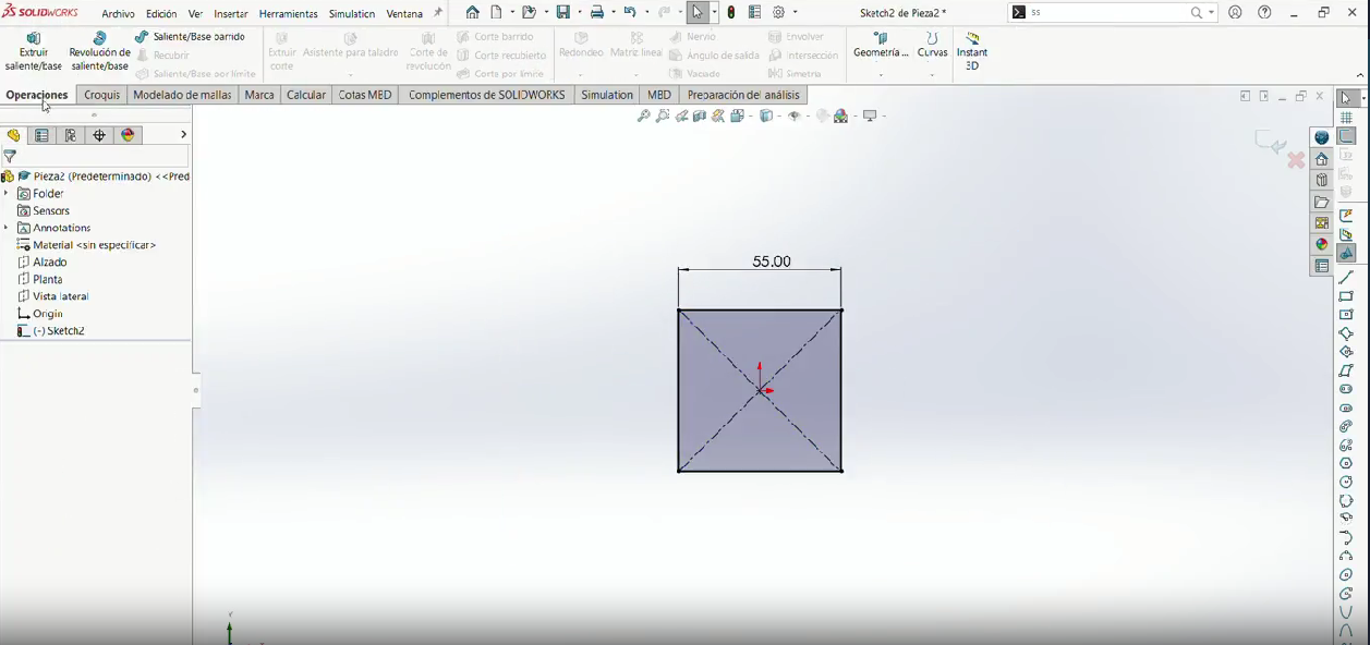
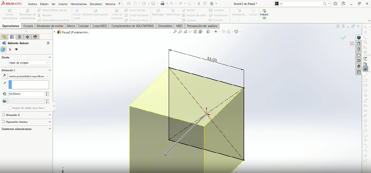
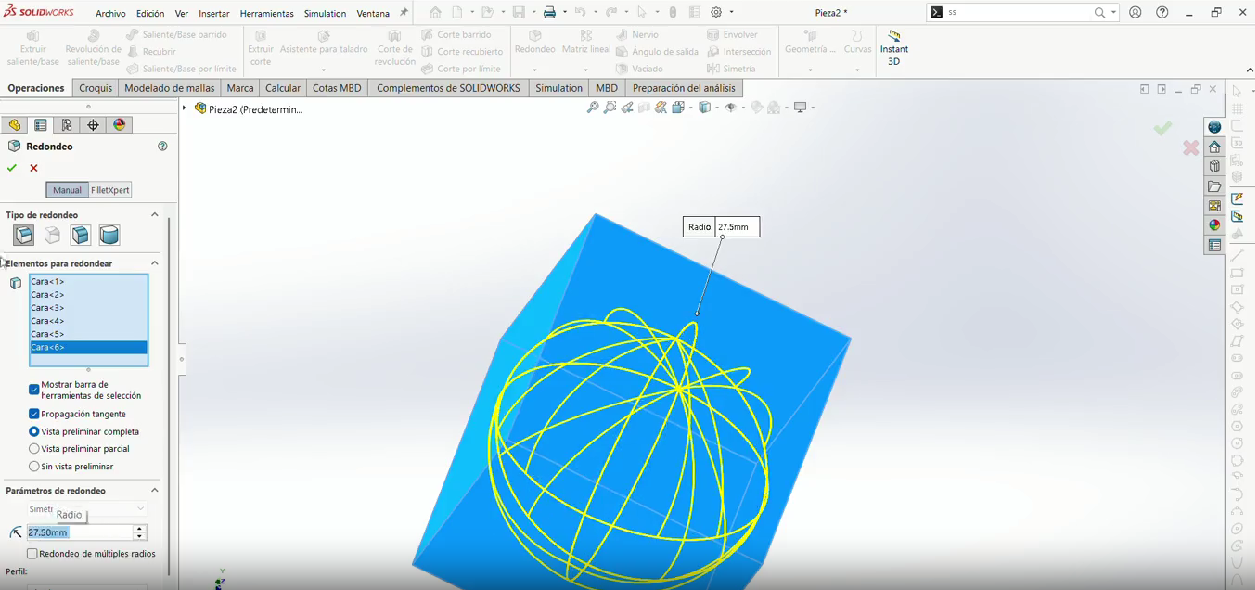
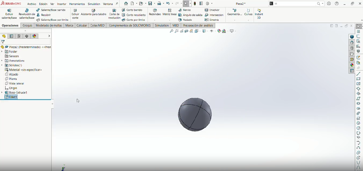
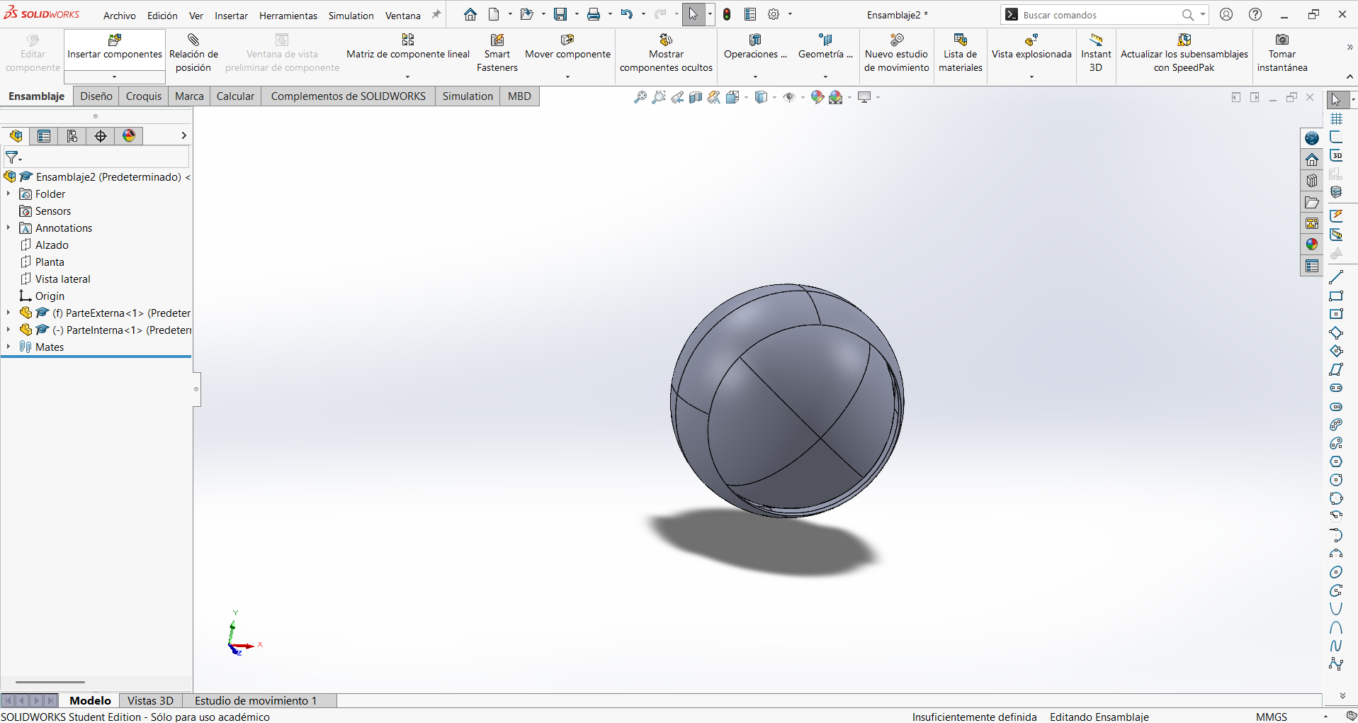
In short: a hinge can of course be machined as separate parts and bolted together, but a single-piece, ready-to-move hinge with an internal trapped gap is only practical with additive manufacturing. That is exactly the property the assignment is asking us to demonstrate. The two extra models below (a captive ball inside a ring, and a print-in-place bearing) show the same principle in different geometries.
Hinge Design
SolidWorks
Why SolidWorks?
I chose SolidWorks because I am certified in this software and it allows advanced parametric modeling. This was critical for:
- Precise tolerance definition
- Clearance control between rotating parts
- Iterative adjustment without redesign
- Mechanical accuracy before printing
Print-in-Place Strategy
The hinge was designed as a single printed component with internal clearances to allow rotation without post-assembly.
Clearance used: 0.3 – 0.5 mm, selected based on:
- Nozzle diameter (0.4 mm)
- Printer dimensional accuracy
- PLA shrinkage behavior
Designed models
I designed three print-in-place models that all rely on trapped internal clearances. Pick a model, then use the second row of buttons to see its parts:
Models (Click to View)
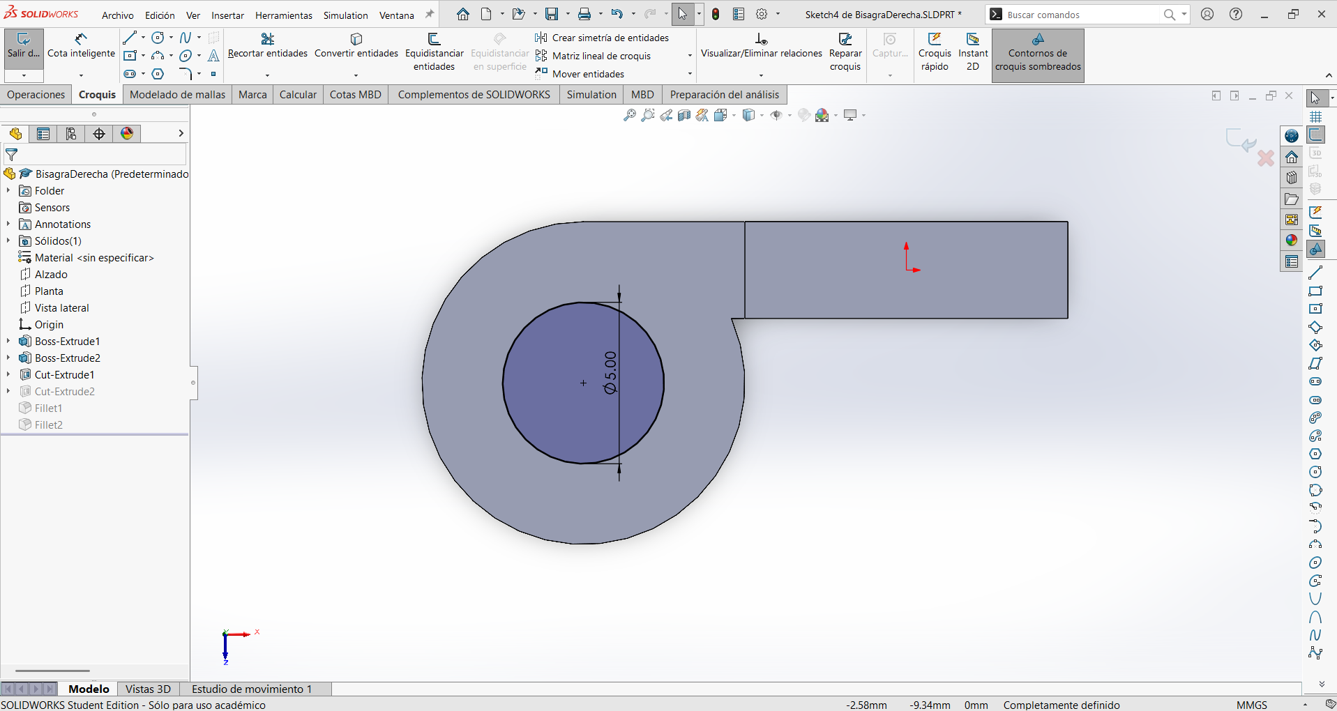
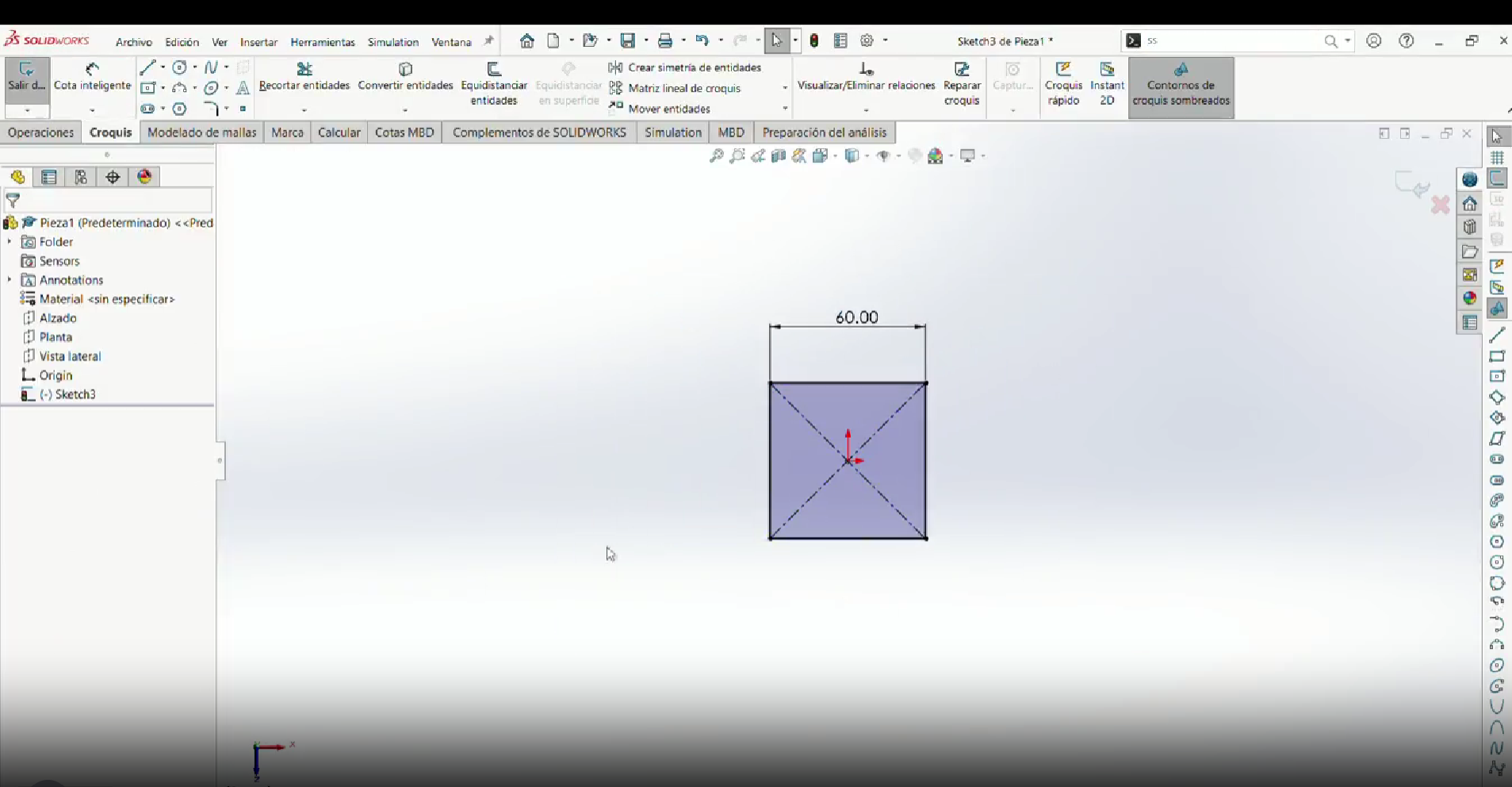
Step 1
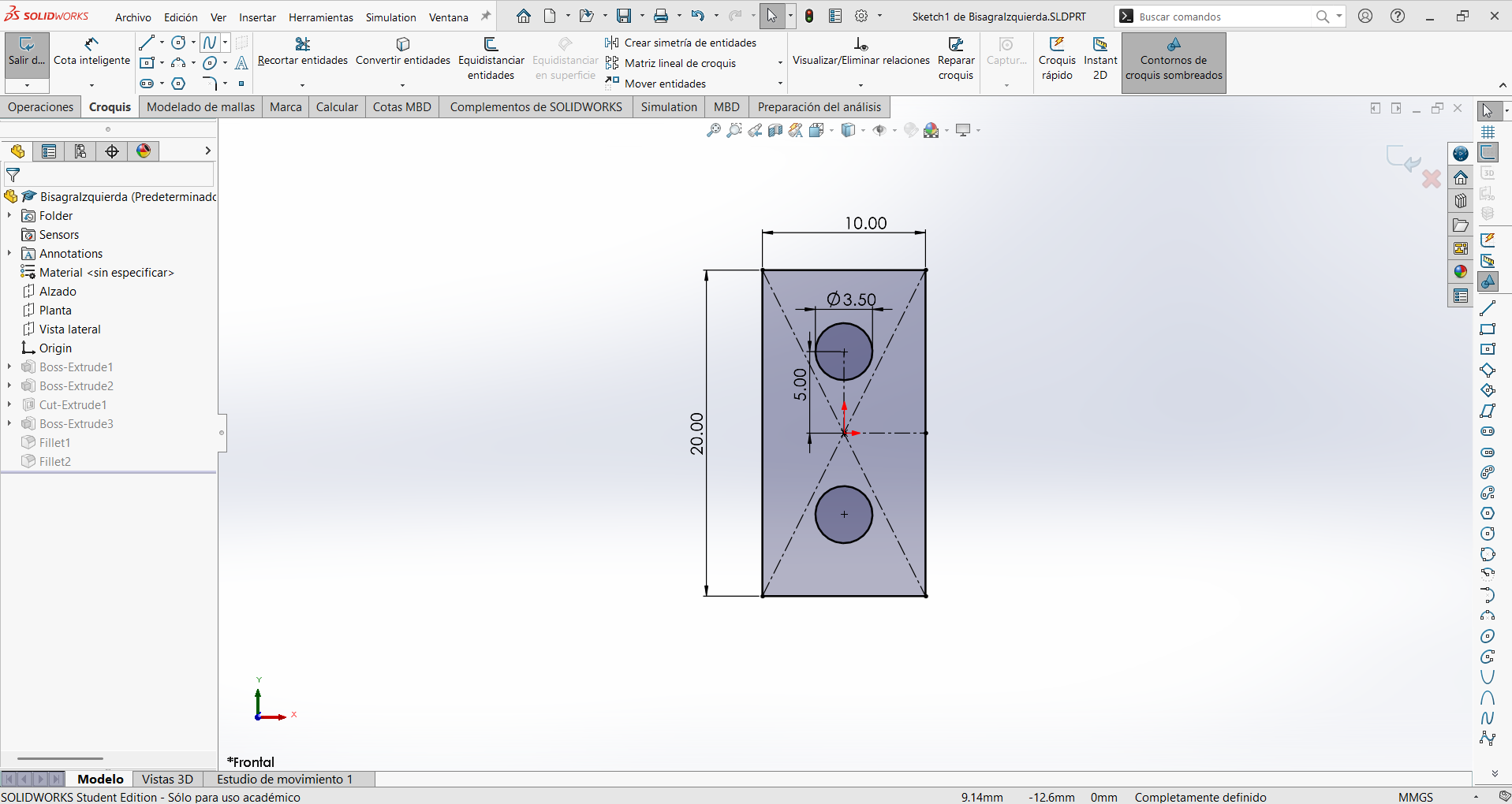
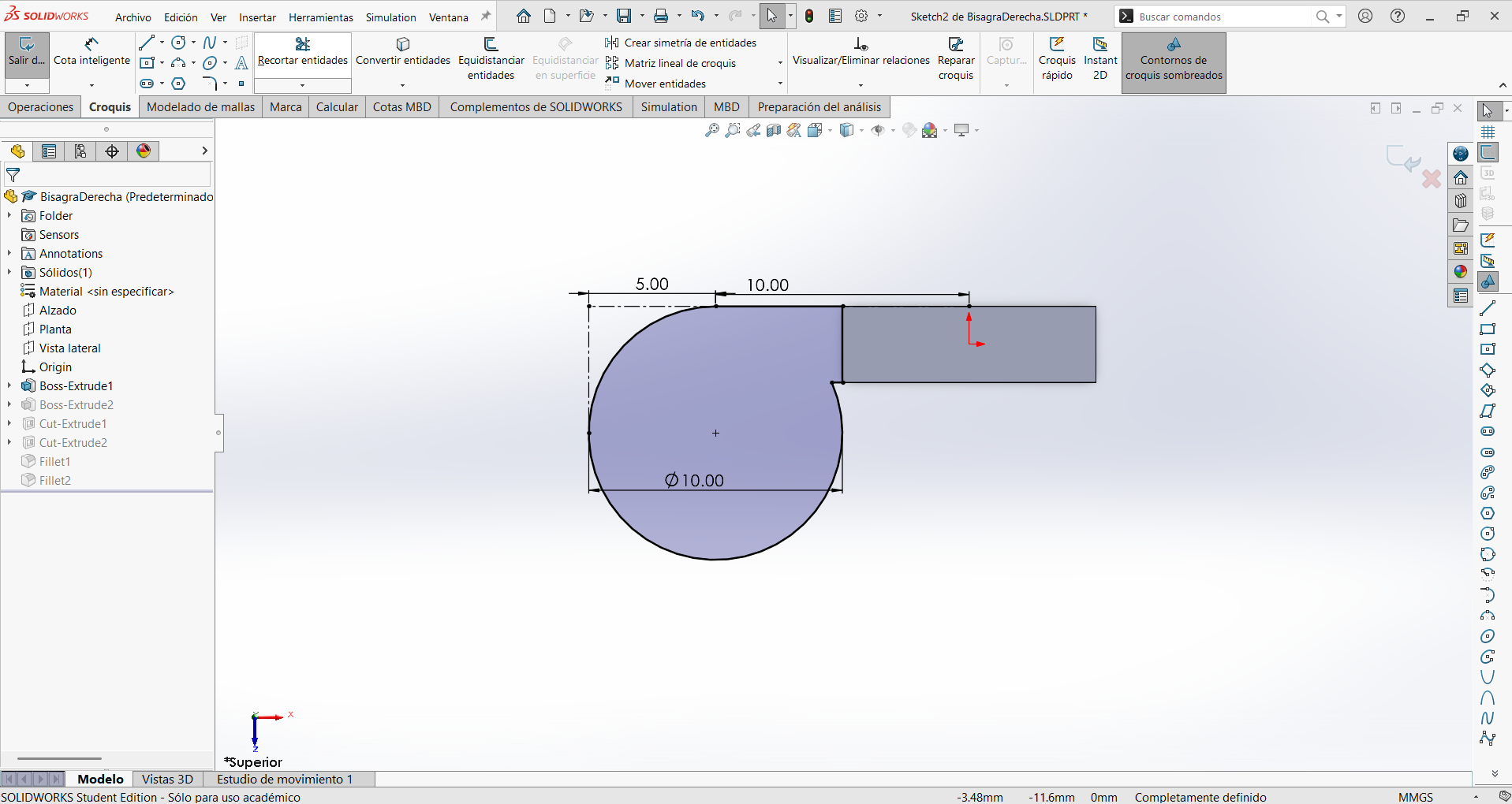
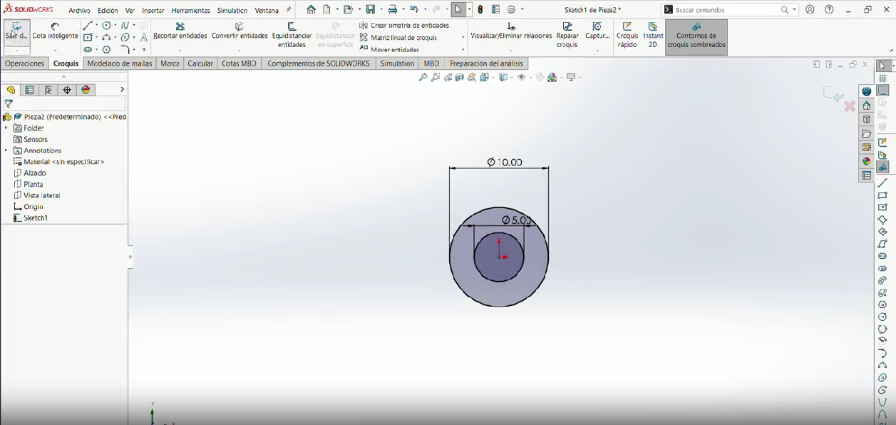
Make a 10.00 mm wide × 20.00 mm tall rectangle. On that sketch I also drew the two mounting holes as 3.5 mm circles, spaced 5.00 mm apart vertically from the center.
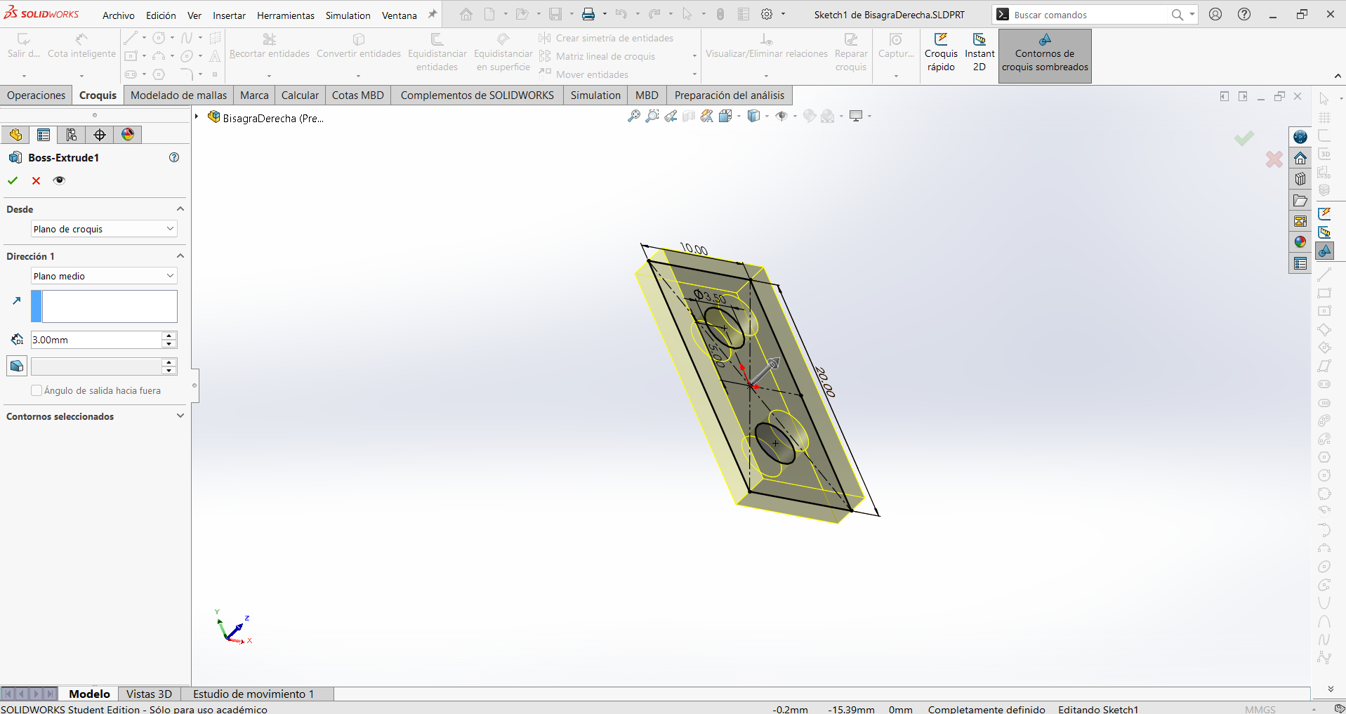
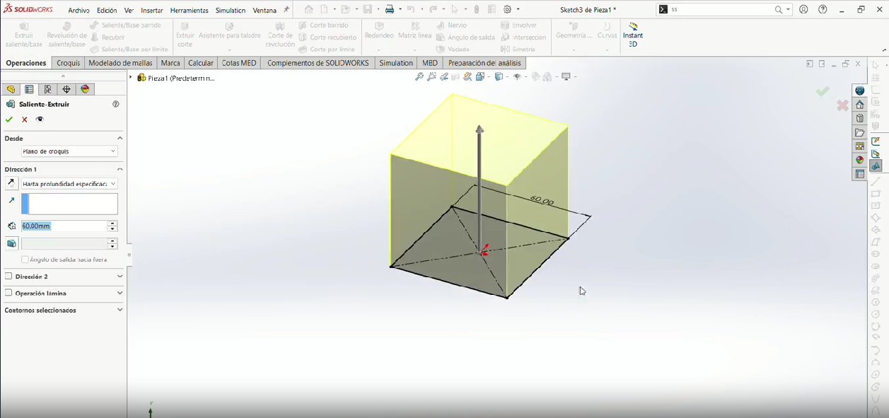
Step 2
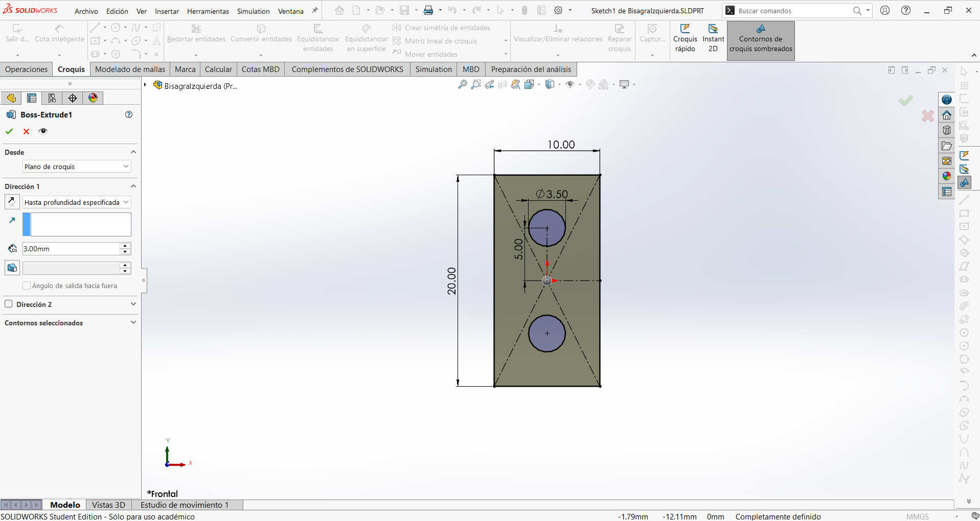
Extrude (3mm) the rectangle and it will have two holes.
Step 3
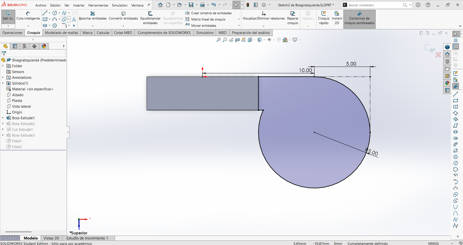
Make a rectangular tab 10.00 mm long that connects to the plate, ending in a R5.00 mm circle that will become the cylindrical barrel of the hinge. The 5.00 mm and 10.00 mm dimensions position the barrel relative to the edge of the plate.
Step 4
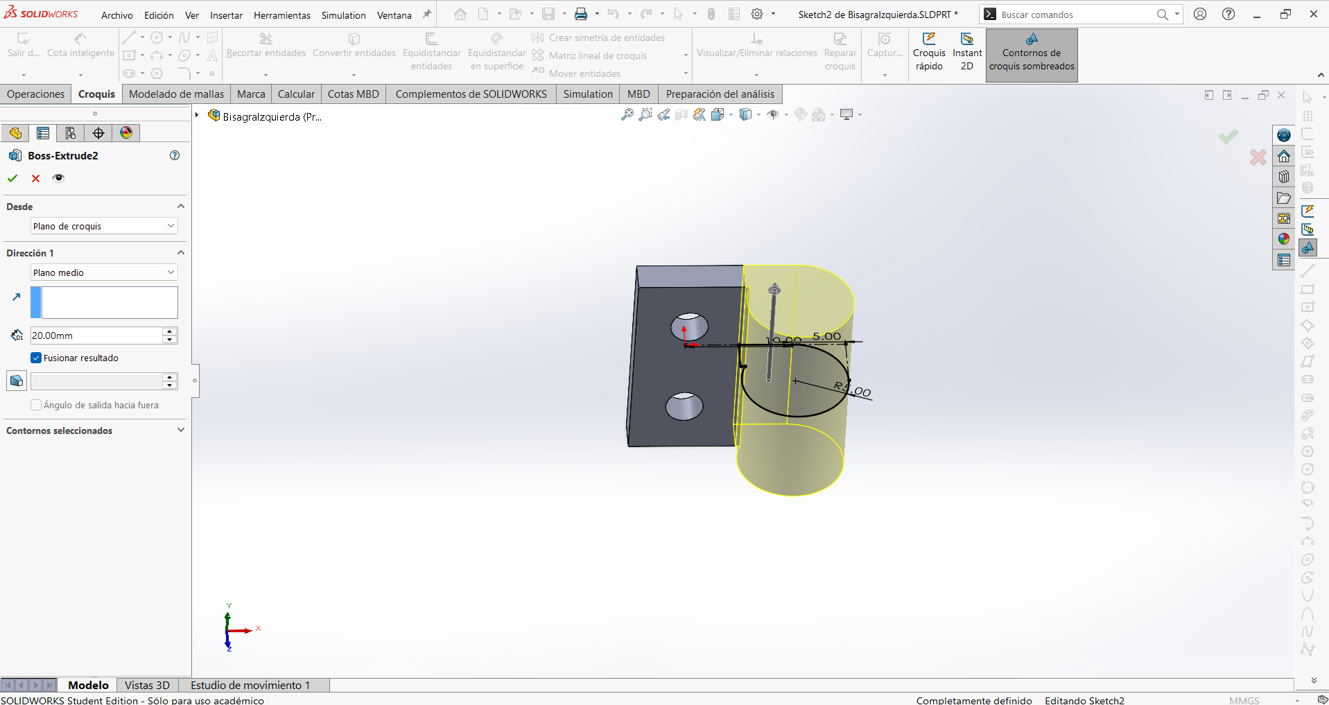
Then extrude the tab so it will be the same tall as the first extrude.
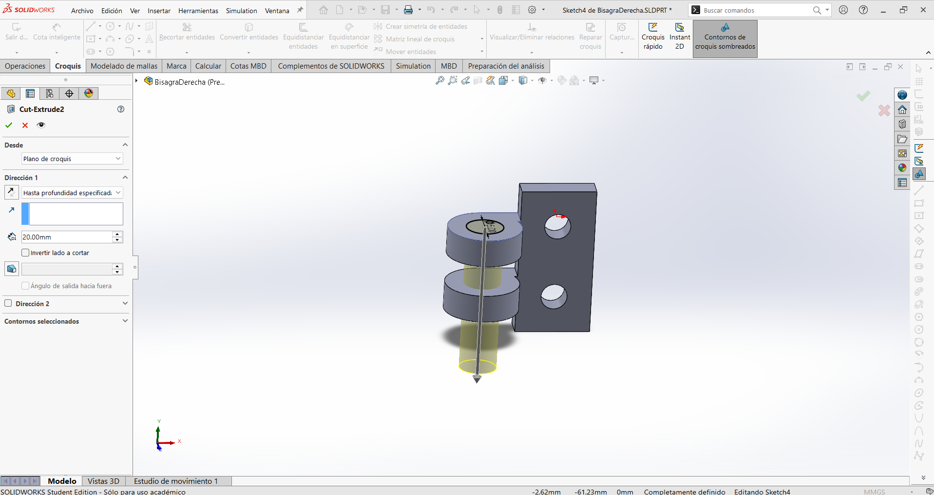
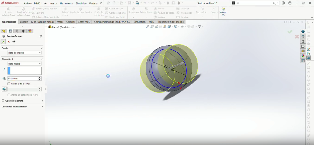
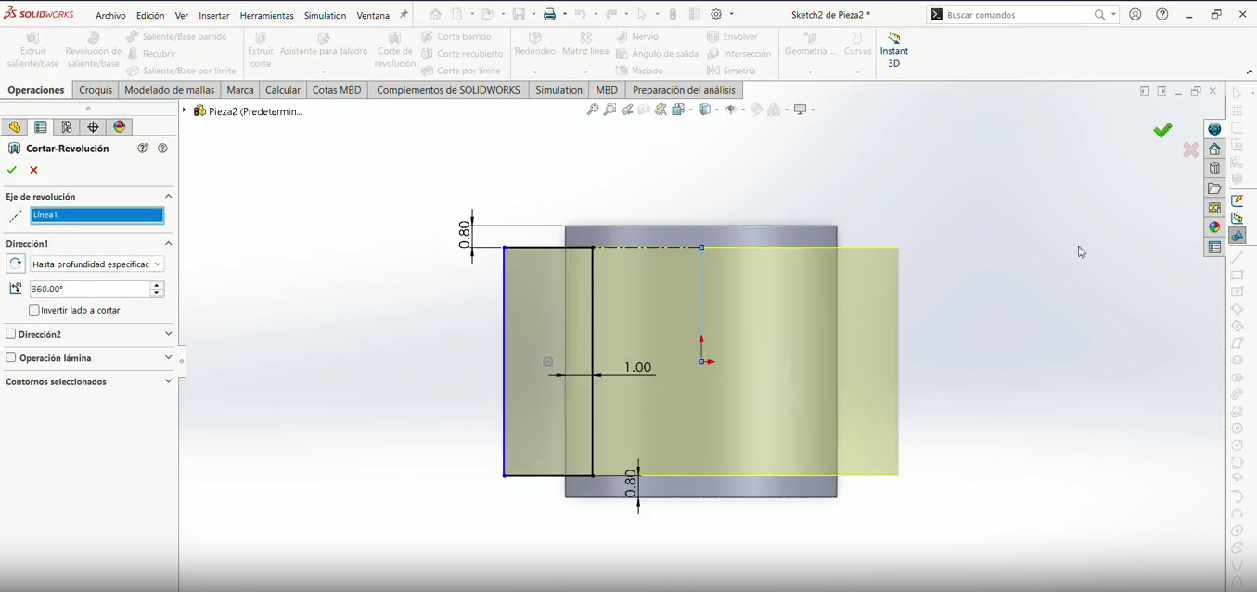
Step 5
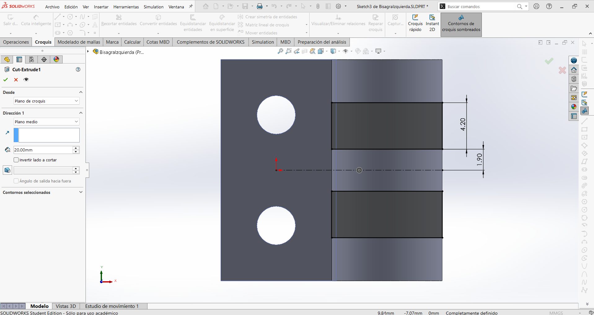
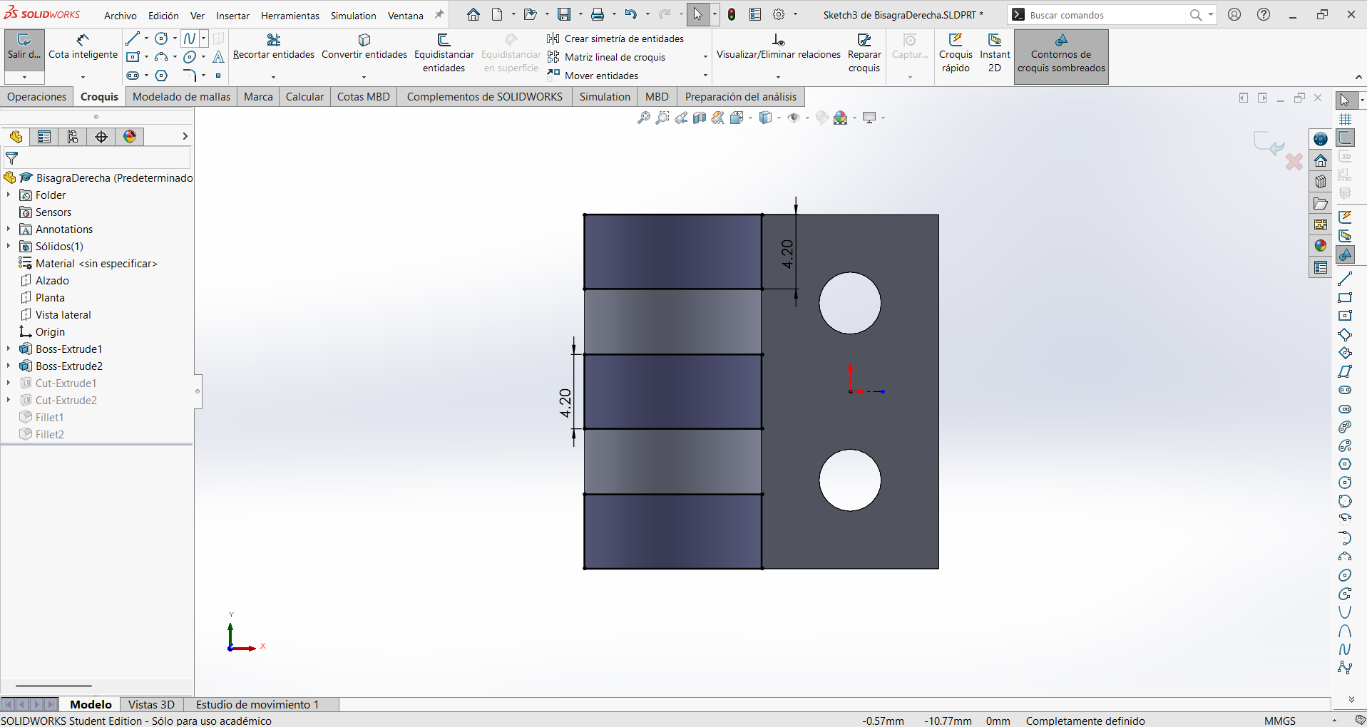
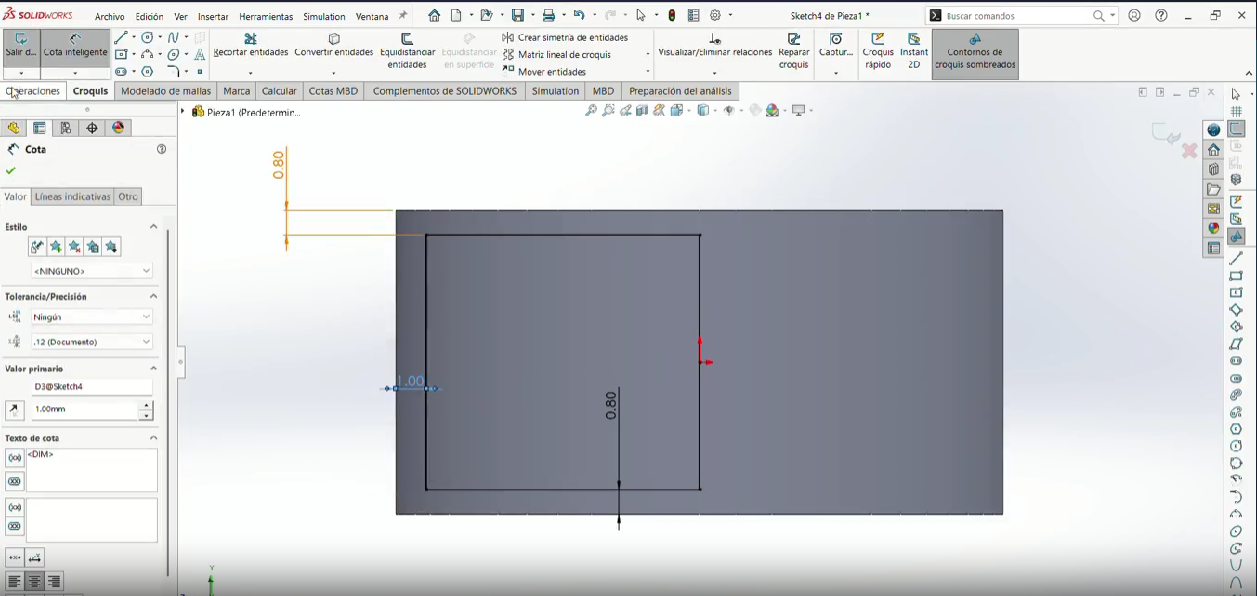
Make two rectangles with the width of the cylinder extrude at the previous step and a tall of 4.2 mm separated by 1.9 mm vertically from the center.
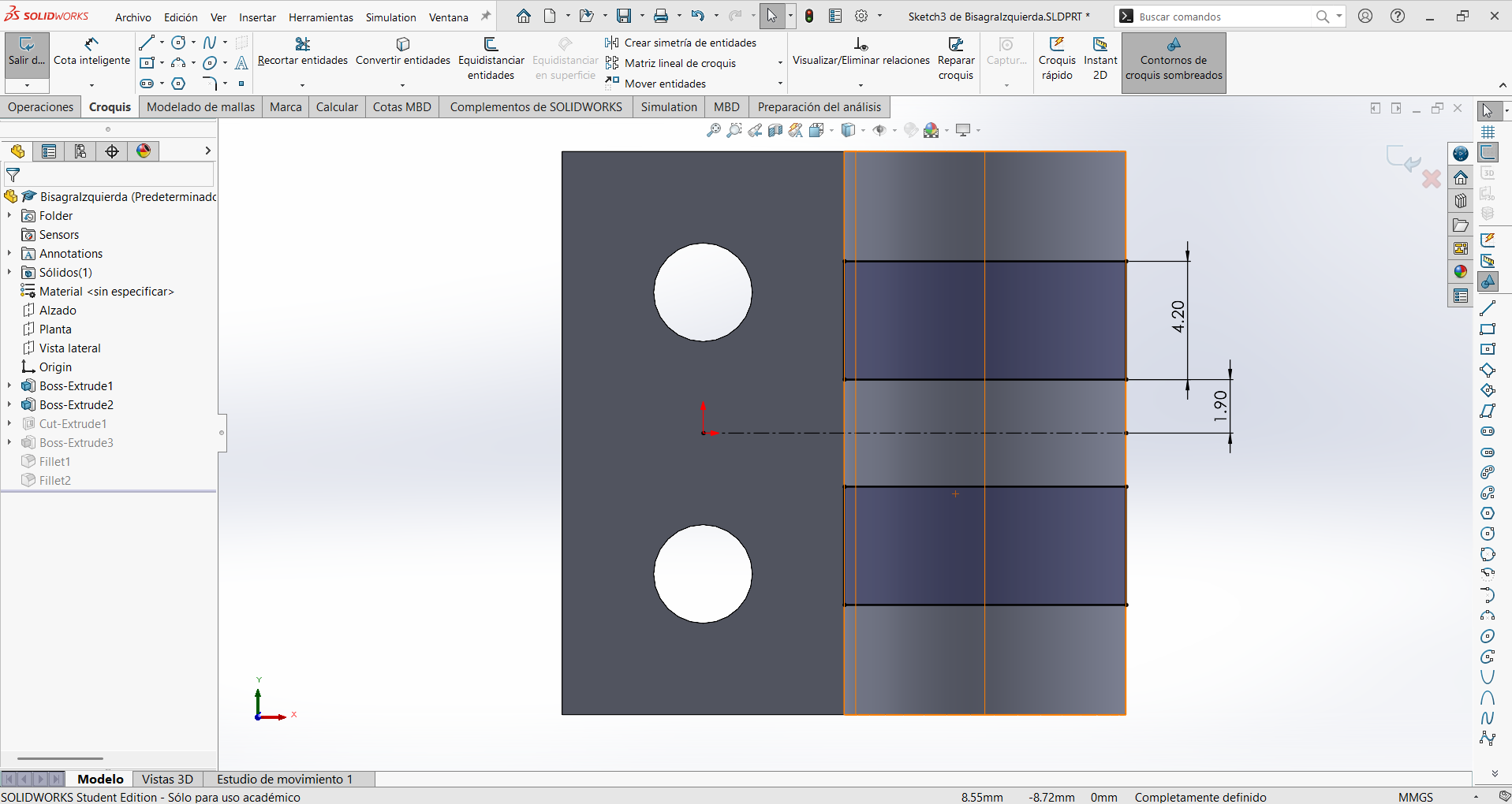
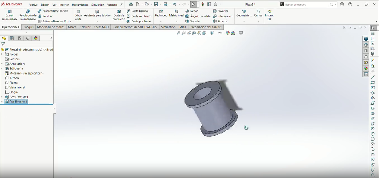
Step 6
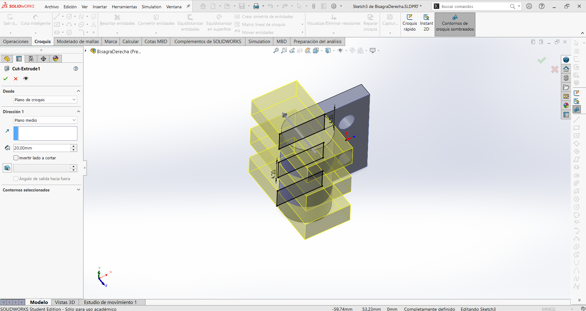
Cut the two rectangles, so it crosses the piece.
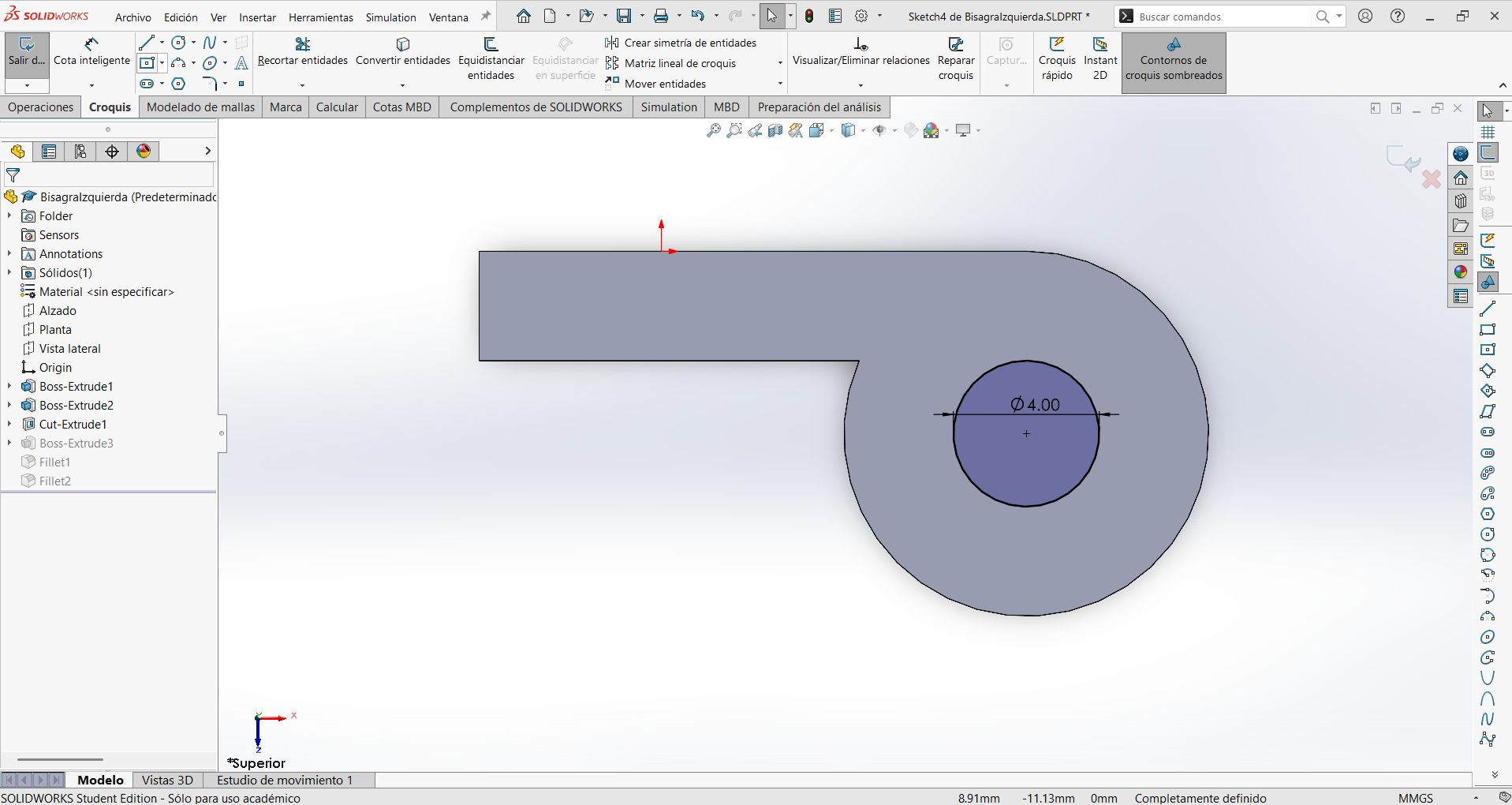
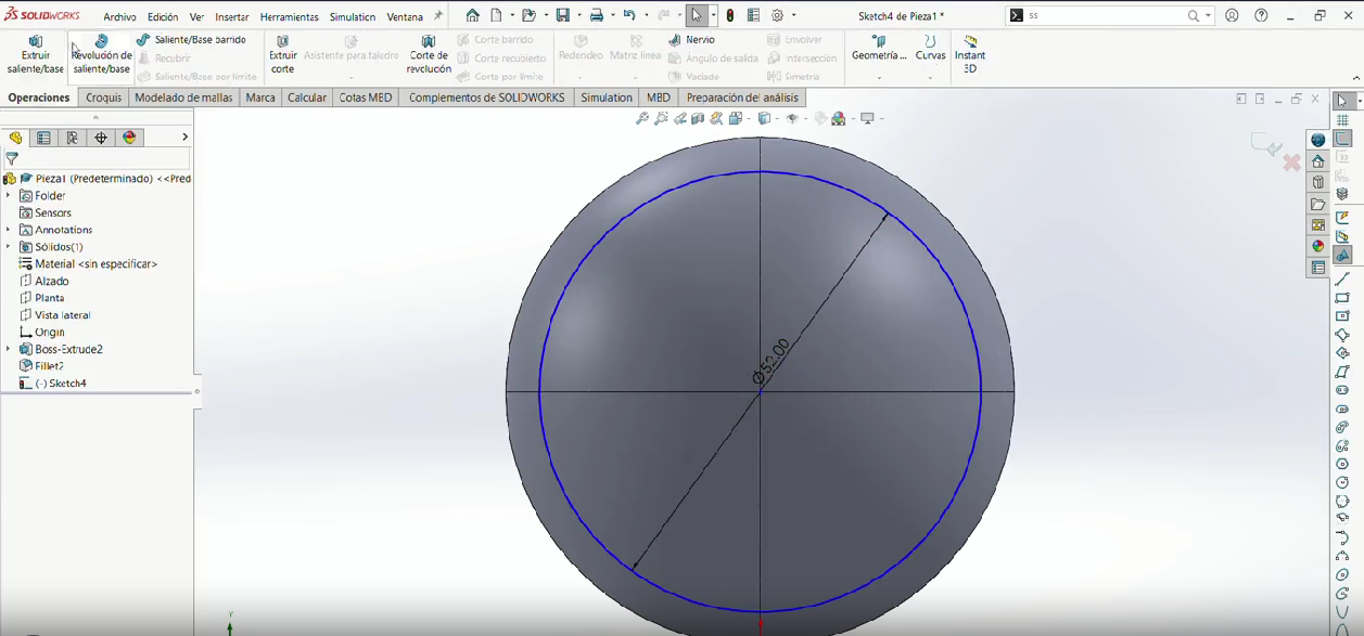
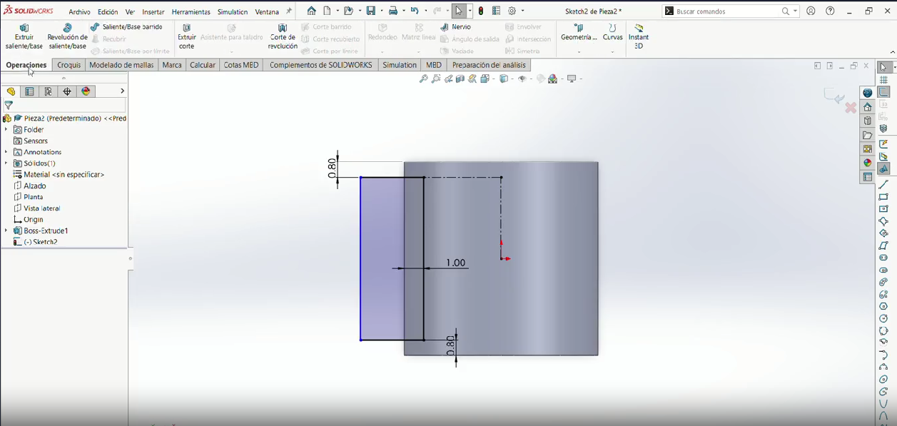
Step 7
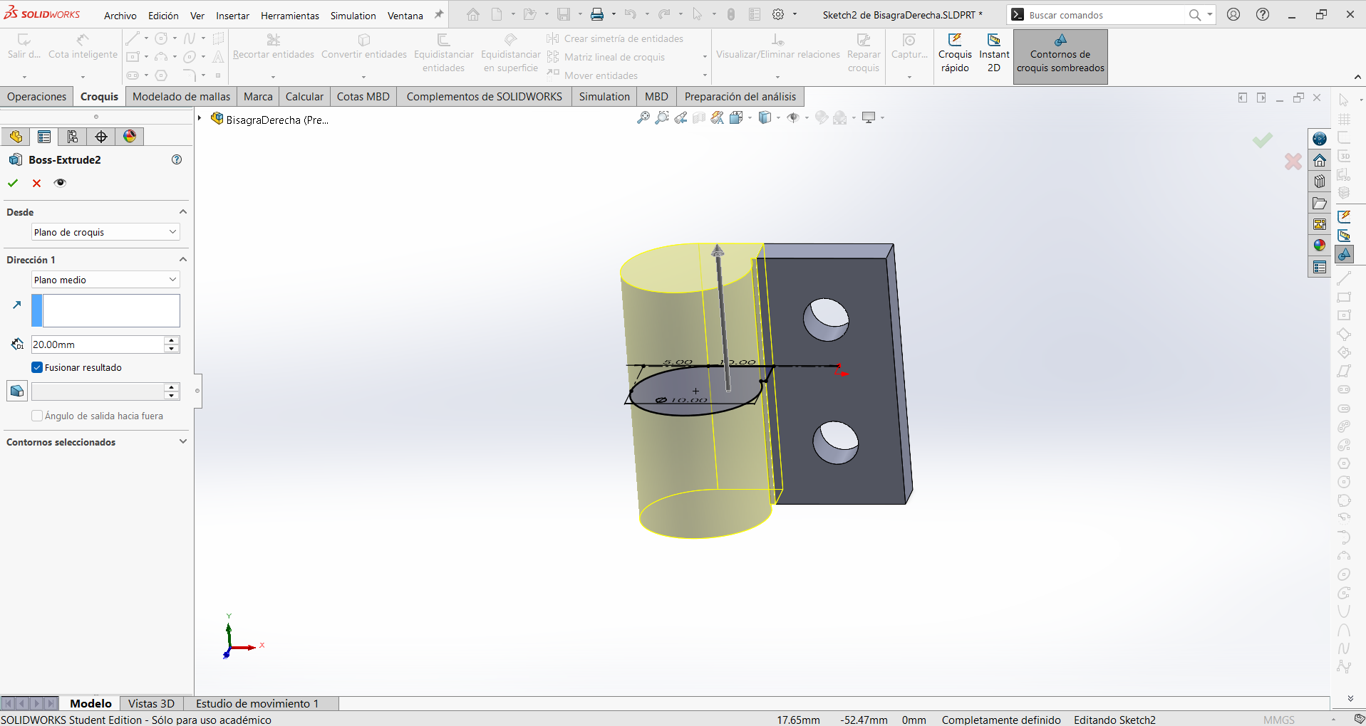
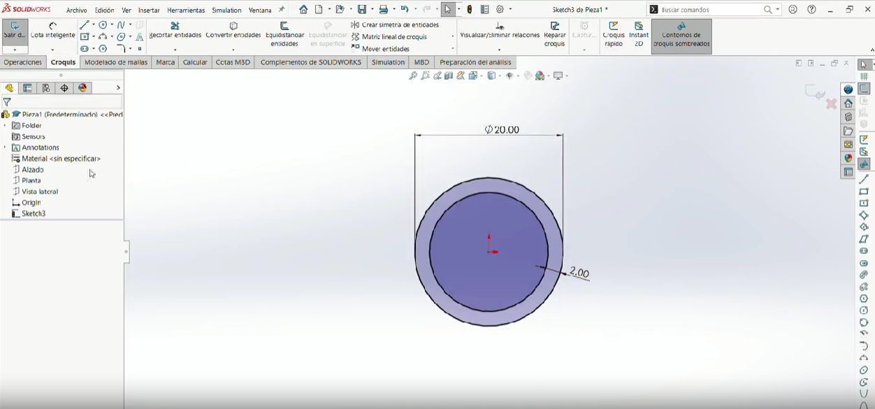
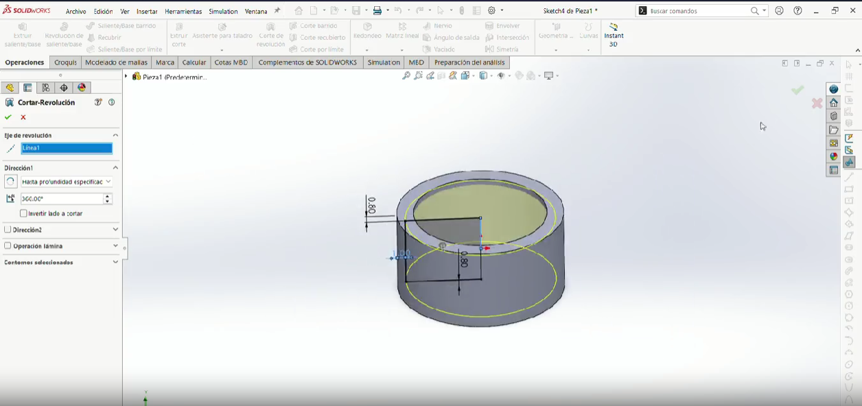
Then the top of the piece make a conectric circle to the cylinder of 4 mm.
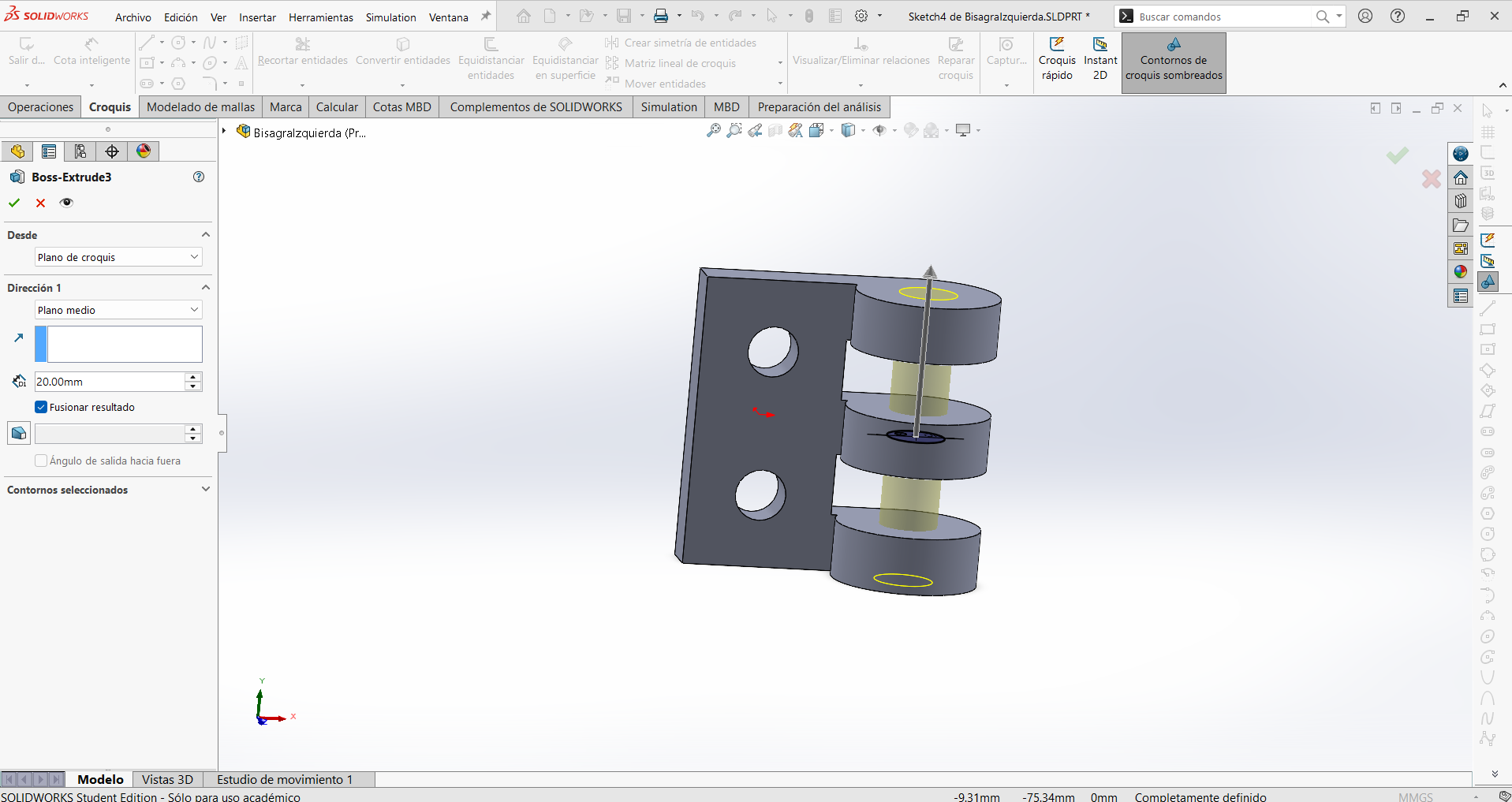
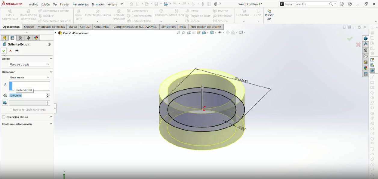
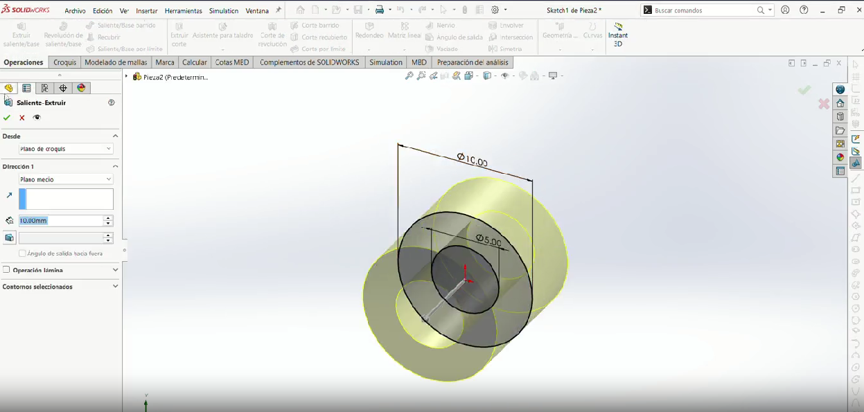
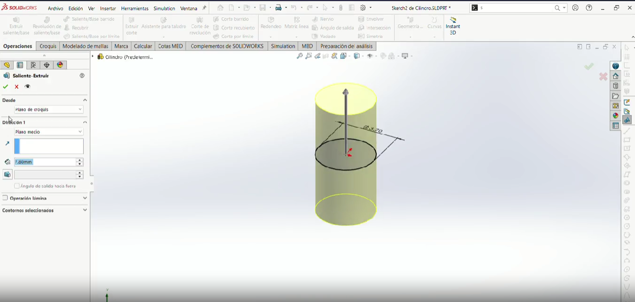
Step 8
Extrude it so it forms a smaller cylinder of 20 mm.
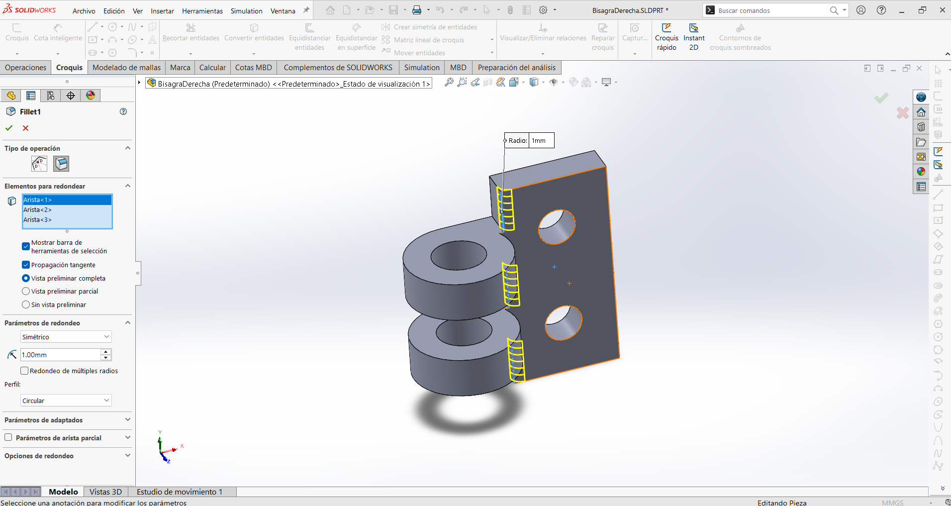
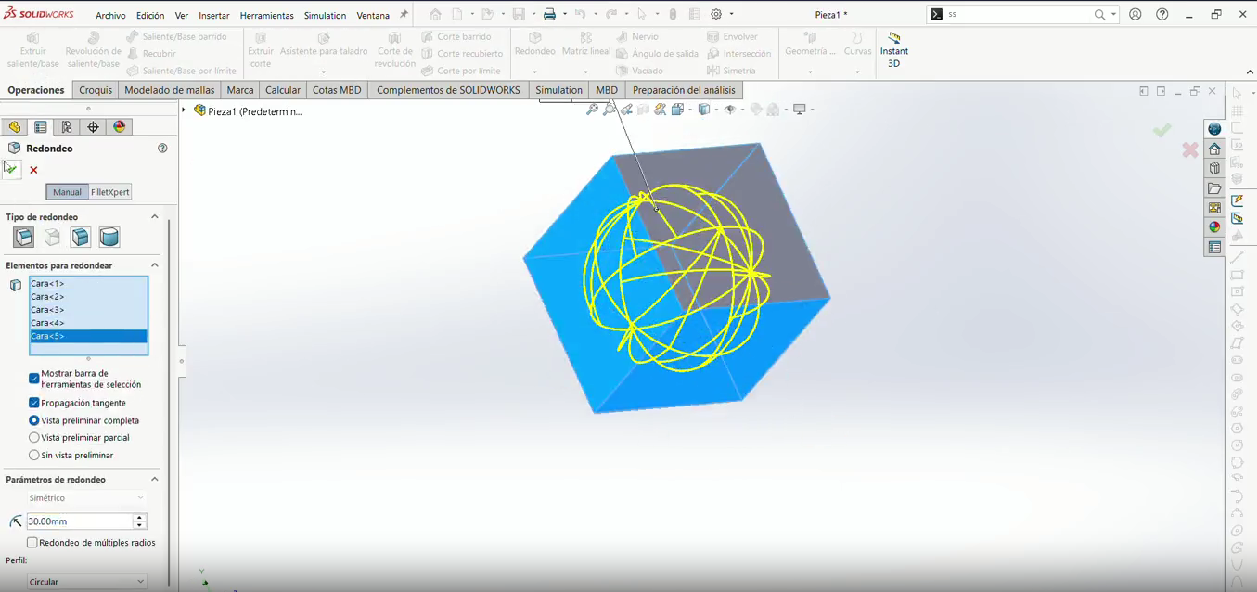
Step 9
Make a fillet (1mm) in the internal corners that looks at the cylinder.
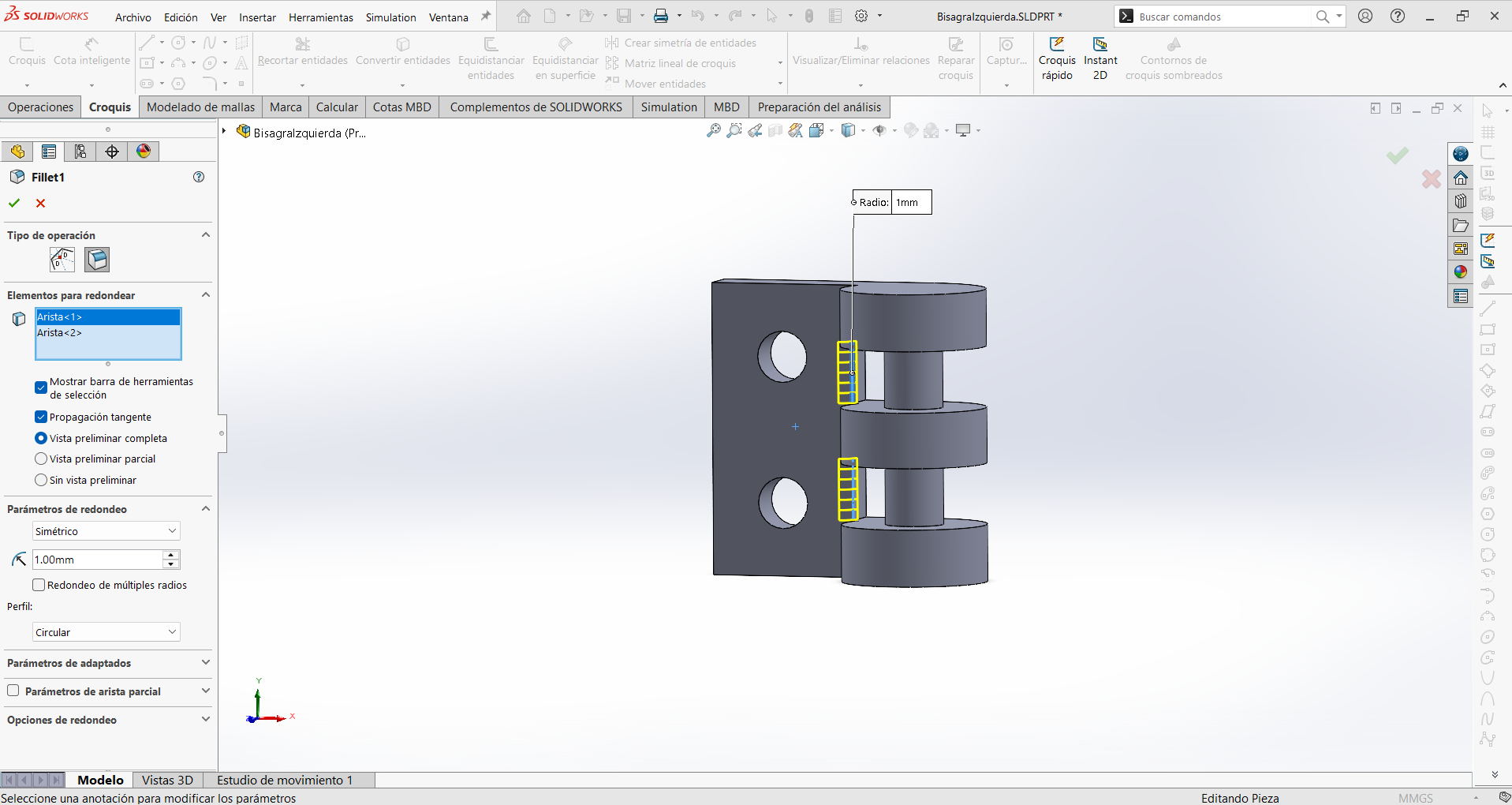
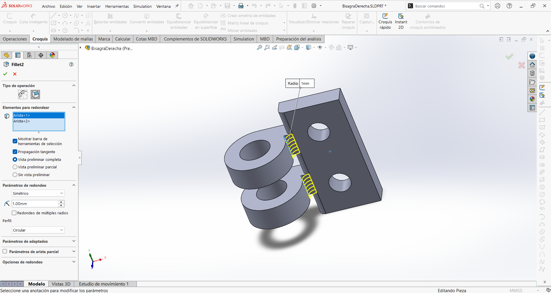
Step 10
Then make another fillet (1mm) in the internal corners that connect the cylinder and the rectangle.

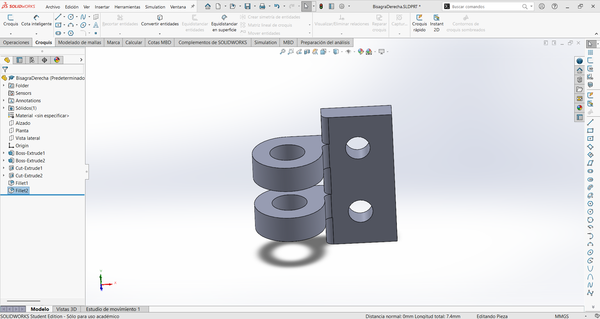
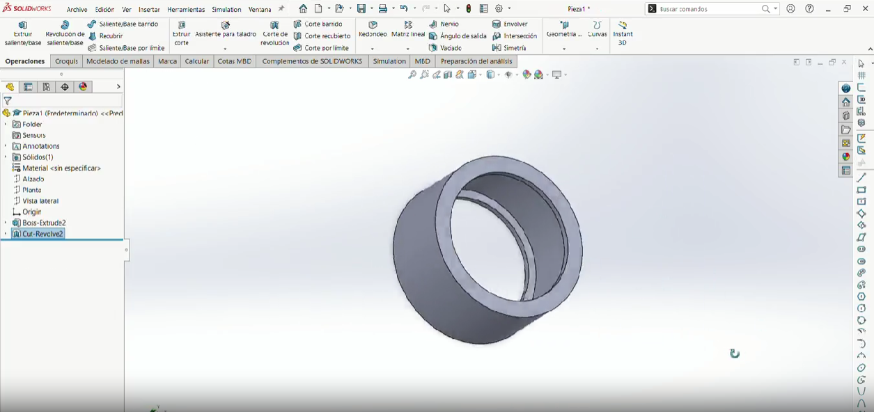
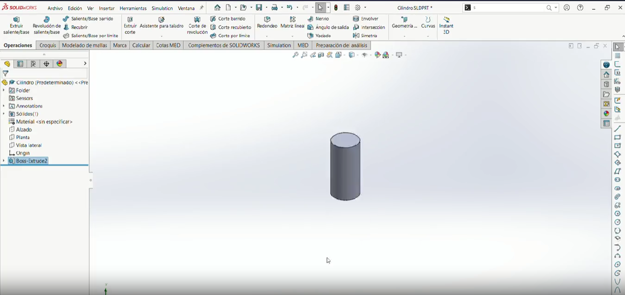
Final Result
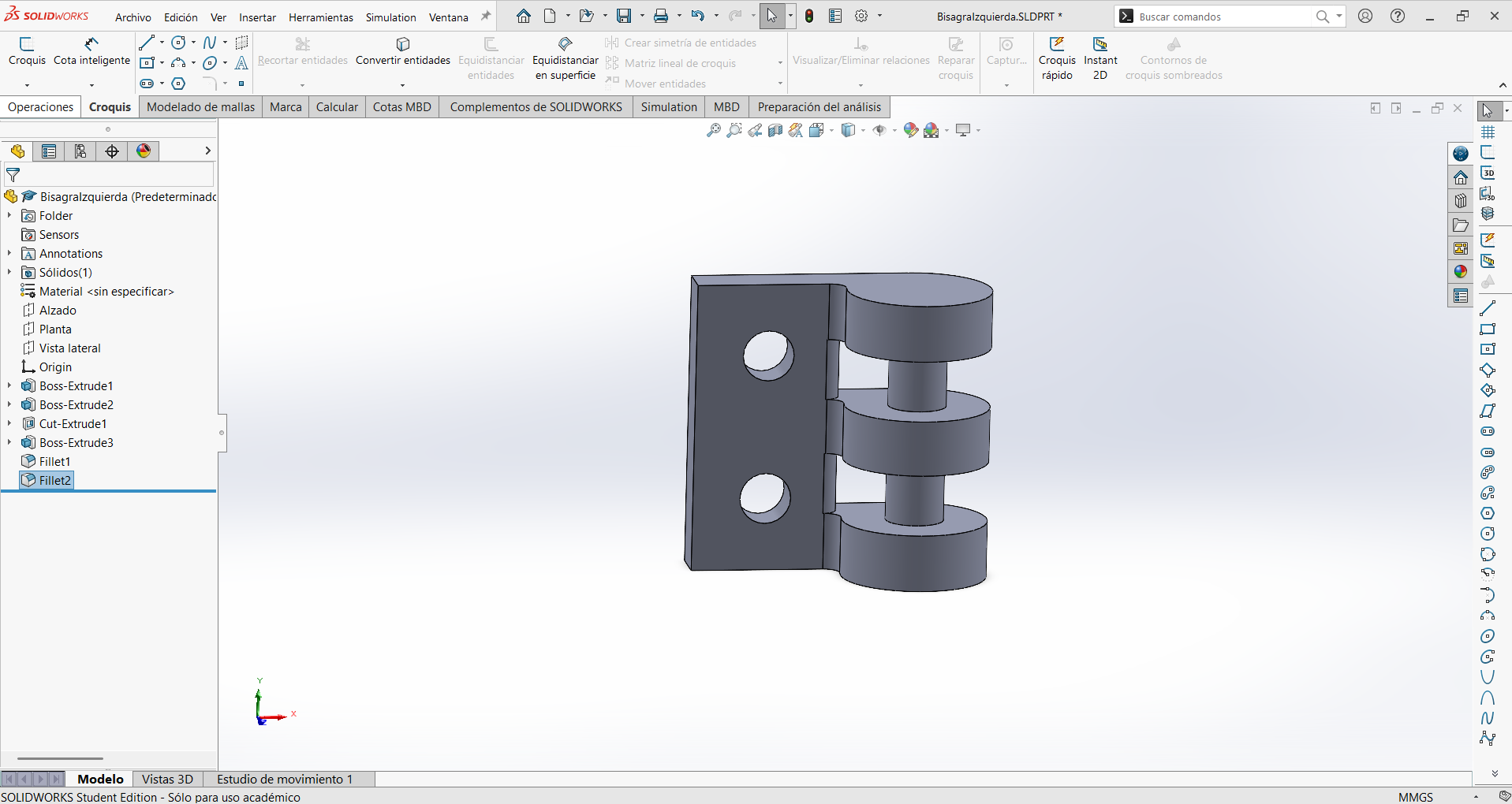
Click to download
Download .SLDPRT Download .STL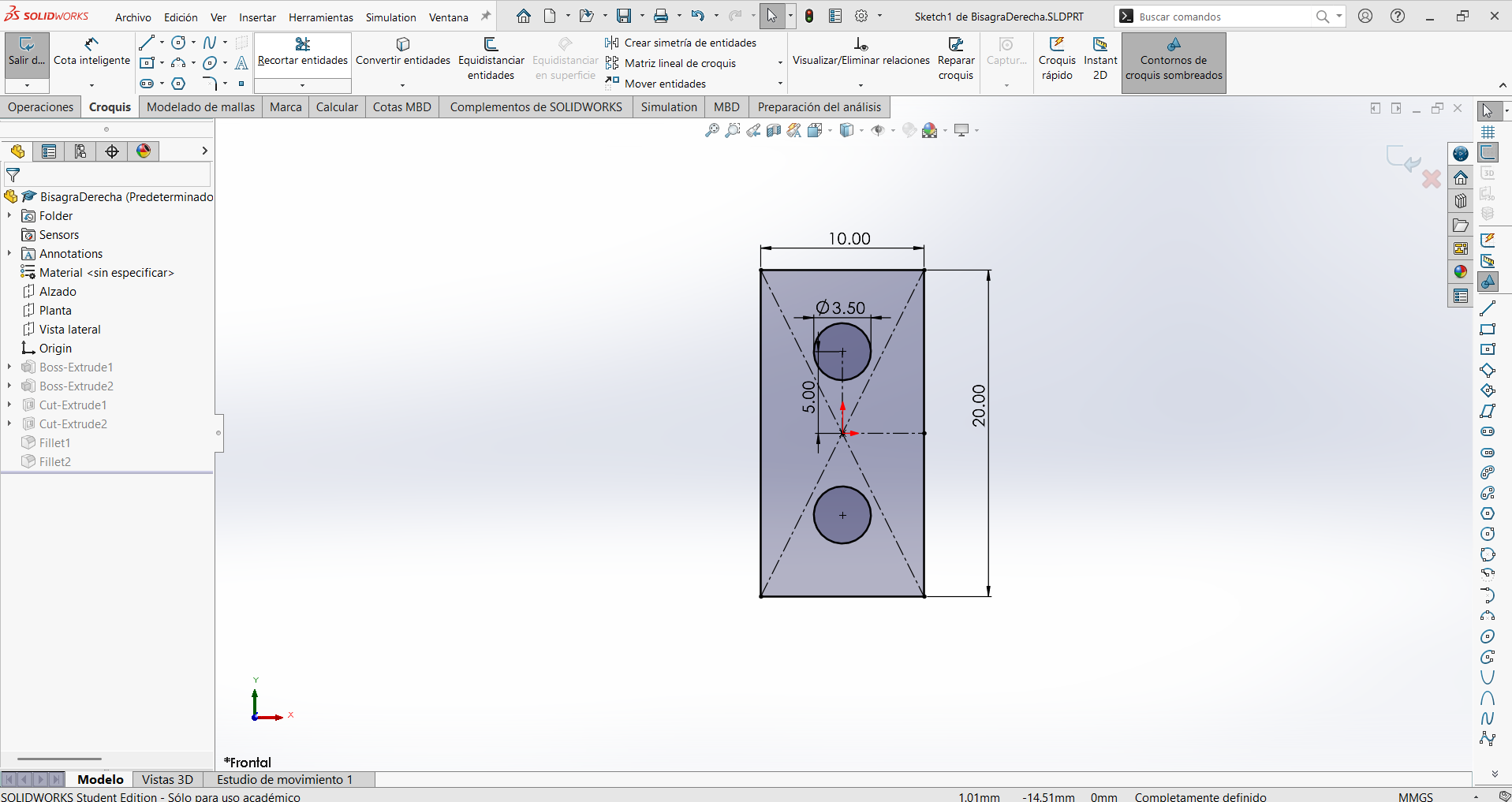
3D Printing
Bambu Studio
I used Bambu Studio for slicing because it provides:
- Accurate layer preview simulation
- Reliable printer profiles
- Precise control of mechanical parameters
Bambu Studio Workflow
Below is the step-by-step slicing workflow I followed in Bambu Studio, from importing the model to sending the print job to the printer.
Step-by-Step Slicing Workflow (Click to view)
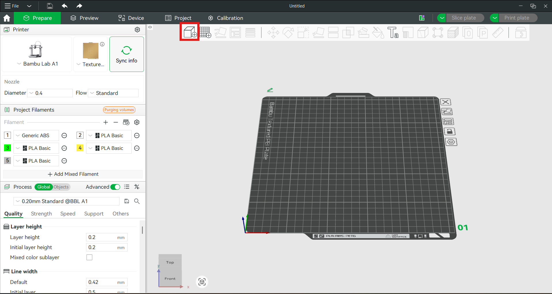
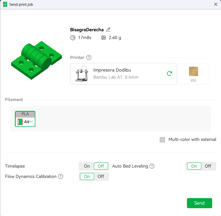
Step 1 — Import the model
Starting from an empty Untitled project, I used the Add / Import button in the top toolbar (highlighted in red) to load the hinge model. Before slicing, the left panel lets you confirm the key setup: the printer profile (Bambu Lab A1), the build plate (Textured PEI Plate), the 0.4 mm nozzle, the project filaments, and the process profile (0.20 mm Standard @BBL A1).
---------------------------------------------------------------------------------------------------------------------------------------------------
Timelapse
The timelapse video below shows the hinge printing in real time, with the first layer adhering to the PEI plate and the subsequent layers building up the geometry. The print-in-place design allows the hinge to be fully functional straight off the bed. In this case, it generate a little bit of stringing, but the hinge still works perfectly.
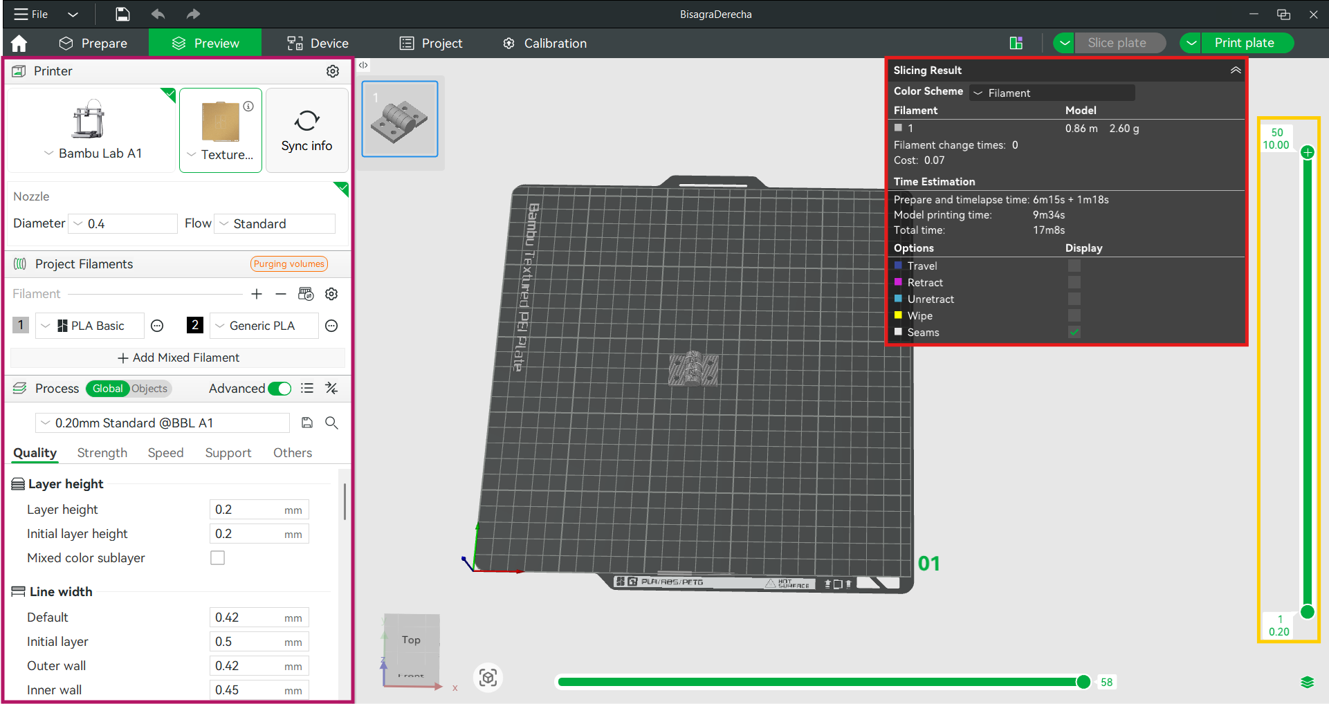
Results
The printed result of each model is shown below. Use the buttons to switch between the hinge, the ball in ring, and the bearing.
As expected, the hinge printed successfully with functional rotation and no post-processing required. The parametric design allowed for quick adjustments in case of fit issues.
3D Printing
Advantages & Limitations
Advantages and limitations of 3D printing
Designing and printing this hinge made the strengths and weaknesses of additive manufacturing very concrete. Below is what I learned firsthand, framed against the alternative subtractive processes.
Advantages
- Trapped and internal geometry: as shown with this hinge, FDM can produce enclosed cavities, internal clearances and pre-assembled moving parts that a cutting tool simply cannot reach.
- Complexity is "free": a complex shape costs the same to print as a simple one of the same volume — there is no extra tooling, fixturing or tool-change cost as there would be in machining.
- No fixturing or tooling: the part is built directly from the model with no jigs, clamps or custom tools.
- Fast, cheap iteration: when the fit was off, I just changed one parametric clearance value and reprinted — no re-tooling.
- Print-in-place assemblies: multiple moving parts come out of one job already working, with no fasteners.
- Low material waste: material is added where needed instead of carving away a whole block.
Limitations
- Anisotropy: printed parts are weaker between layers (in Z) than along them, so layer orientation matters for a load-bearing hinge.
- Dimensional accuracy & tolerances: clearances below the nozzle diameter (0.4 mm) are unreliable; I had to tune 0.3–0.5 mm gaps empirically, and shrinkage shifts real dimensions.
- Overhangs & support: steep overhangs need support material, which costs time and leaves marks; I avoided this with the print-in-place orientation.
- Surface finish: visible layer lines, rougher than a machined surface.
- Speed for volume: for many identical simple parts, subtractive or molding methods are faster; FDM shines for one-offs and complexity.
- Material range: limited to printable thermoplastics, with properties below many machined metals.
The takeaway is that 3D printing is not "better" than machining in general — it is better for a specific class of problems: complex, internal, pre-assembled or one-off geometry, which is exactly what this hinge represents.
3D Scanning
Polycam
Polycam
Digitizing a real object
The second requirement of the week is to use scanning technology to digitize a real object. I scanned my own 3D printer: a relatively large, geometrically complex object with frames, rods and openings, which makes it a good test of what photogrammetry can capture. The goal was to turn a physical machine into a usable digital 3D model.
Step-by-step scanning workflow
Below is the full step-by-step process I followed to scan the printer with Polycam, from installing the app to exporting the model into CAD.
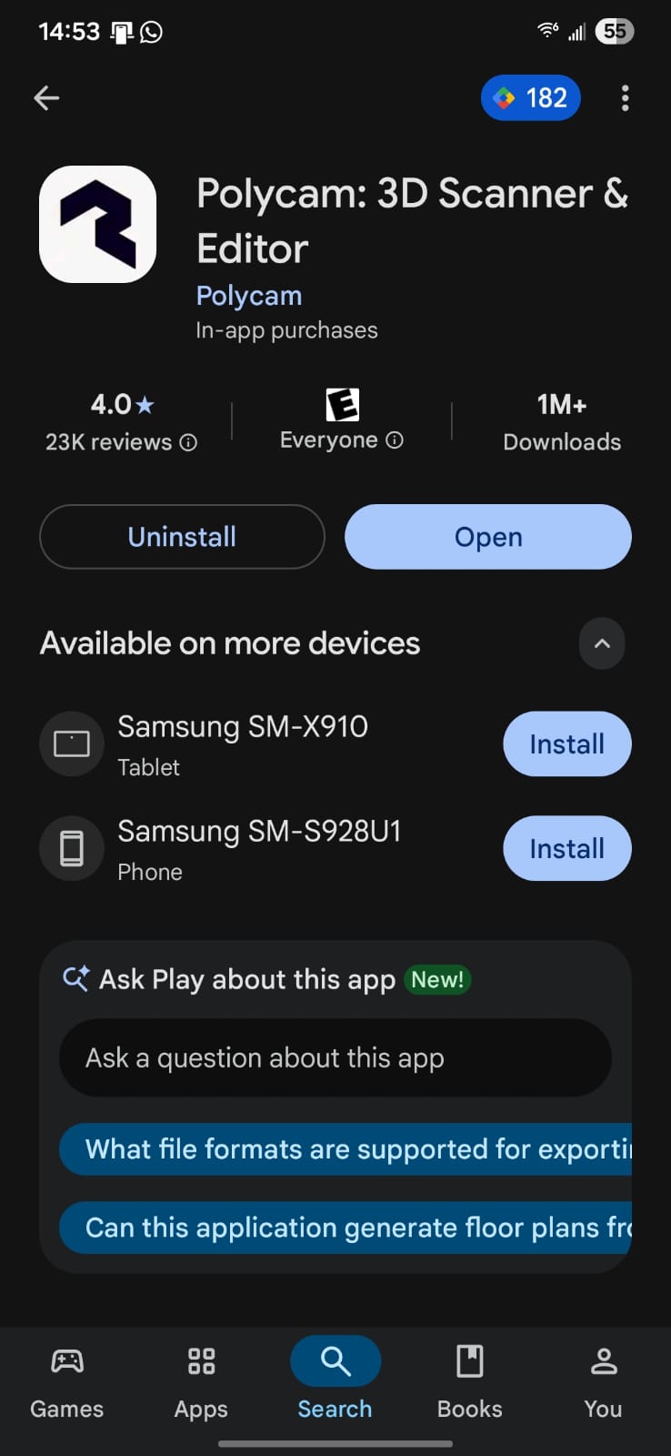
Step 1 — Download the app
I installed Polycam on my phone from the app store. Polycam is free to start and supports photogrammetry, which is the mode I used (it builds a 3D model from a set of photos, so it works with a normal phone camera without needing a LiDAR sensor).
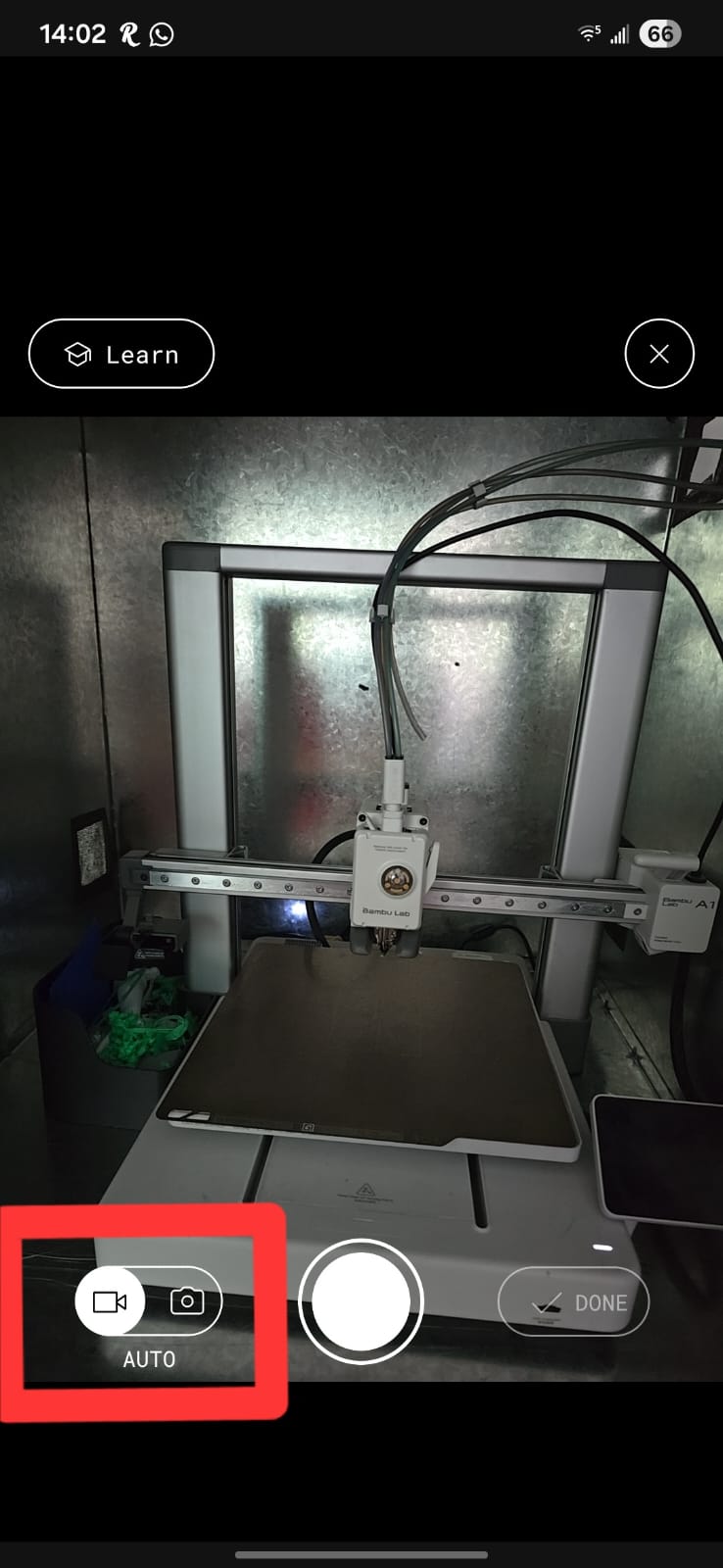
Step 2 — Choose Auto mode
Inside the app I selected the Auto capture mode, which reconstructs the object from still images that takes will you are moving around the object. This mode is the best choice for an object like a printer that has fine detail and I want to measure later.
Step 3 — Capture photos around the object
I walked slowly around the printer taking overlapping photos from every angle and height — 100 images in total. The key is good overlap between consecutive photos and even, diffuse lighting, so the software can find common feature points between images.
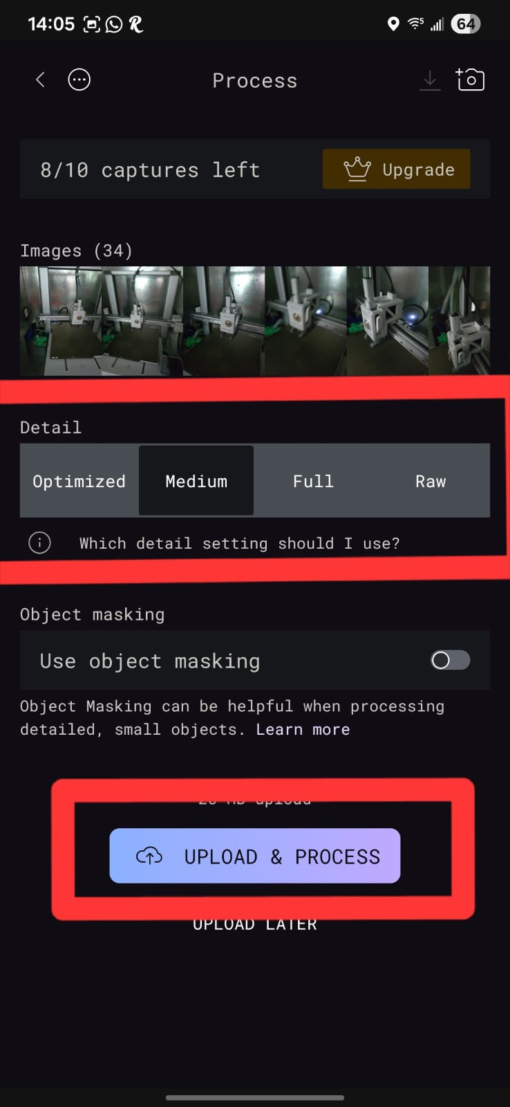
Step 4 — Process the scan
After capturing, I let Polycam process the images in the cloud. The whole capture-and-process took about 15 minutes. Polycam finds the common feature points, triangulates them into a 3D point cloud, and builds a textured mesh.
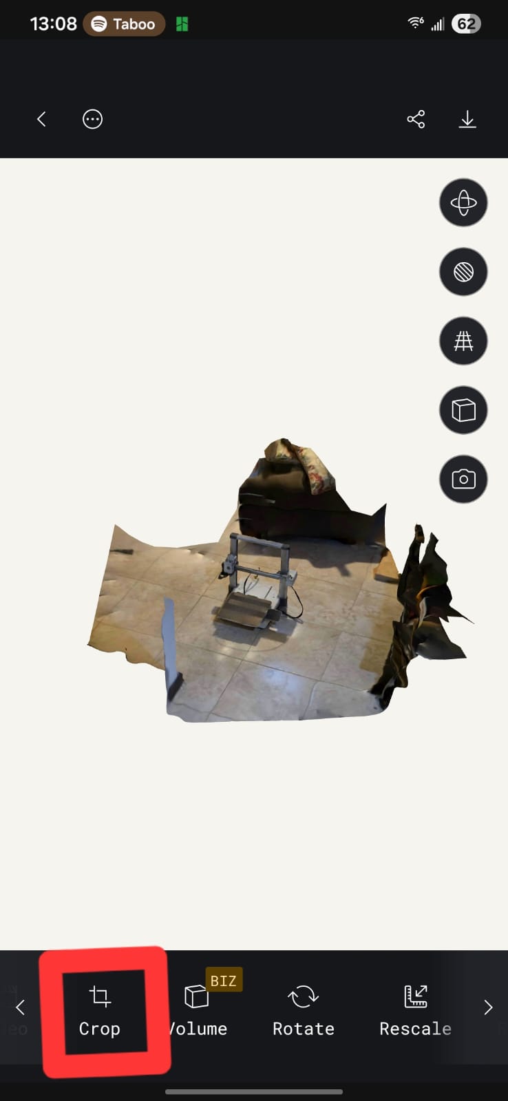
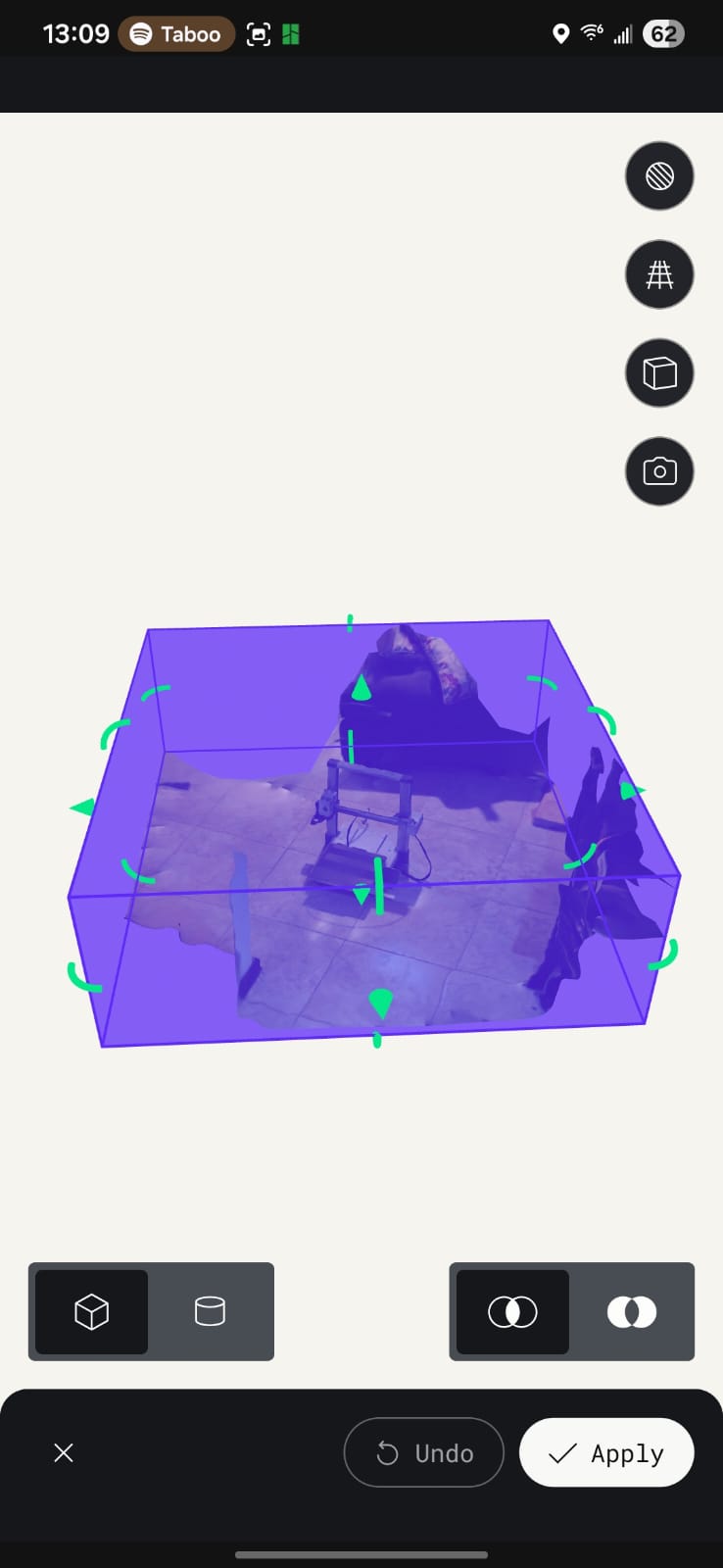
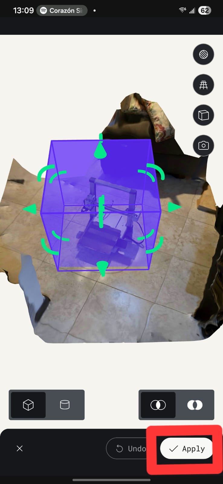
Step 5 — Crop the 3D model
After processing, I cropped the 3D model to focus on the printer's main body, removing any unnecessary background or extraneous geometry.
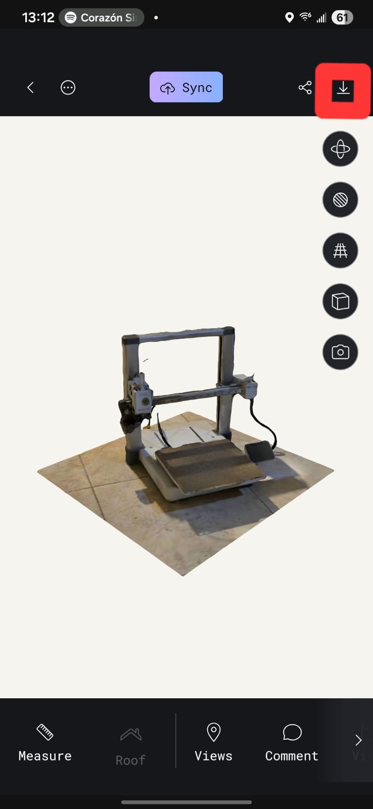
Step 6 — Review and export
Finally I reviewed the result (texture, mesh and clay views below) and exported it as OBJ/STL so I could import it into CAD and use it as a dimensional reference for the enclosure design.
How photogrammetry digitizes an object
In short: Polycam takes the set of overlapping photos, finds common feature points that appear in several images, and uses the parallax between viewpoints to triangulate each point's position in 3D space. From that point cloud it builds a surface mesh and projects the original photos back onto it as a texture. The result is a digital twin of the physical printer that I can measure and import into CAD — exactly the "physical → digital" direction that complements the "digital → physical" direction of 3D printing.
Video 1-Texture
Texture mapping of the 3D scan showing the detailed surface information captured by Polycam. This texture provides visual context for spatial analysis and integration planning.
The scan does not replace caliper measurements but provides spatial validation and integration support.
Final Project Impact
This week directly supports the mechanical architecture of my final project.
- The hinge validates dynamic articulation.
- The scan ensures dimensional compatibility.
- The workflow reduces mechanical uncertainty.
By combining parametric modeling, controlled additive manufacturing, and spatial scanning, I ensured that my final system is dimensionally accurate and mechanically reliable.