As part of this week, our group worked together on the embedded programming group assignment, comparing different microcontroller architectures and their toolchains — datasheets, programming workflows, performance, and power consumption — and documenting our shared findings before our individual projects. You can read the complete group assignment, including our comparisons and shared documentation, here:
Group AssignmentGroup Assignment
Project Overview
Control of a servo motor using a list of angles received via UART and navigated with buttons.
- Project: Servo Angle List Control
- Author: Rodrigo Zárate
- Platform: Raspberry Pi Pico 2
- Communication: UART 115200 bps
- Control: PWM ~50 Hz
Datasheet Raspberry Pi Pico 2
General Information
| Microcontroller | RP2040 (designed by Raspberry Pi) |
| CPU | Dual-core ARM Cortex-M0+ |
| Clock Speed | Up to 150 MHz |
| Architecture | 32-bit |
| SRAM | 264 KB on-chip RAM |
| Flash Memory | External QSPI flash (typically 2 MB on Pico board) |
GPIO & Peripherals
| GPIO Pins | 26 multi-function GPIO (digital I/O) |
| ADC | 12-bit ADC (up to 4 external analog inputs) |
| PWM | 16 PWM channels (8 slices) |
| UART | 2 × UART controllers |
| SPI | 2 × SPI controllers |
| I²C | 2 × I²C controllers |
| PIO | 2 × Programmable I/O blocks (custom hardware interfaces) |
| Timers | Hardware timers and watchdog |
Electrical Characteristics
| Operating Voltage (Logic) | 3.3V |
| Input Voltage (VSYS) | 1.8V – 5.5V |
| GPIO Logic Level | 3.3V (Not 5V tolerant!) |
| ADC Reference | 3.3V default (external reference possible) |
Special Features
- Dual-core processing for multitasking applications.
- Programmable I/O (PIO) for custom communication protocols.
- Flexible clock system with PLL configuration.
- USB 1.1 device and host support.
- Low power sleep modes.
The RP2040 is optimized for embedded systems projects requiring precise timing, multiple communication interfaces, and flexible PWM control.
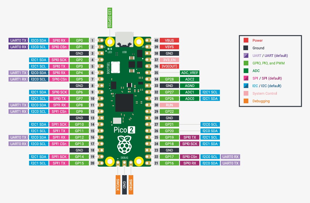
Pinout Legend (Color Key)
This table explains what each color category means in the Pico 2 pinout diagram.
| Category | Color | Description | Typical Use |
|---|---|---|---|
| Power | Red | Voltage supply pins that power the board and external devices (e.g., VBUS, VSYS, 3V3). | Powering sensors, modules, and the Pico itself. |
| Ground | Black | 0V reference. Required as a common reference for power and signals. | Shared GND between Pico and external circuits. |
| UART (default) | Purple | Serial communication pins (TX/RX). “Default” indicates common recommended assignments. | Serial console, debugging, GPS/Bluetooth modules. |
| GPIO / PIO / PWM | Green | General-purpose digital pins. Can read inputs, drive outputs, generate PWM, and run PIO functions. | Buttons, LEDs, relays, servo PWM, motor control PWM. |
| ADC | Dark Green | Analog-to-digital input pins for reading varying voltages (only certain GPIOs support ADC). | Potentiometers, analog sensors, voltage measurement. |
| SPI (default) | Pink | High-speed serial bus (SCK/MOSI/MISO/CS). “Default” indicates common pin mapping. | SD cards, fast displays, high-speed sensors. |
| I2C (default) | Blue | Two-wire bus (SDA/SCL). Multiple devices can share the same bus. | OLEDs, IMUs, temperature sensors, RTC modules. |
| System Control | Light Pink | Pins related to internal board control (reset, regulator enable, analog reference, etc.). | RUN reset, 3V3_EN, ADC_VREF (advanced use). |
| Debugging | Orange | Programming and debug interface pins (SWD). Used with external debug probes. | SWDIO/SWCLK for debugging and low-level development. |
Tip: Most beginner projects use Power, Ground, and GPIO/PWM. UART/I2C/SPI are used when communicating with other devices.
Important: Servo must be powered with 5–6V and share GND with Pico.
Connections
| Device | GPIO | Function |
|---|---|---|
| Servo Signal | GP15 | PWM 50 Hz |
| Mode Button | GP16 | Change mode |
| Next Button | GP17 | Next angle |
| Previous Button | GP18 | Previous angle |
| UART TX | GP0 | Serial TX |
| UART RX | GP1 | Serial RX |
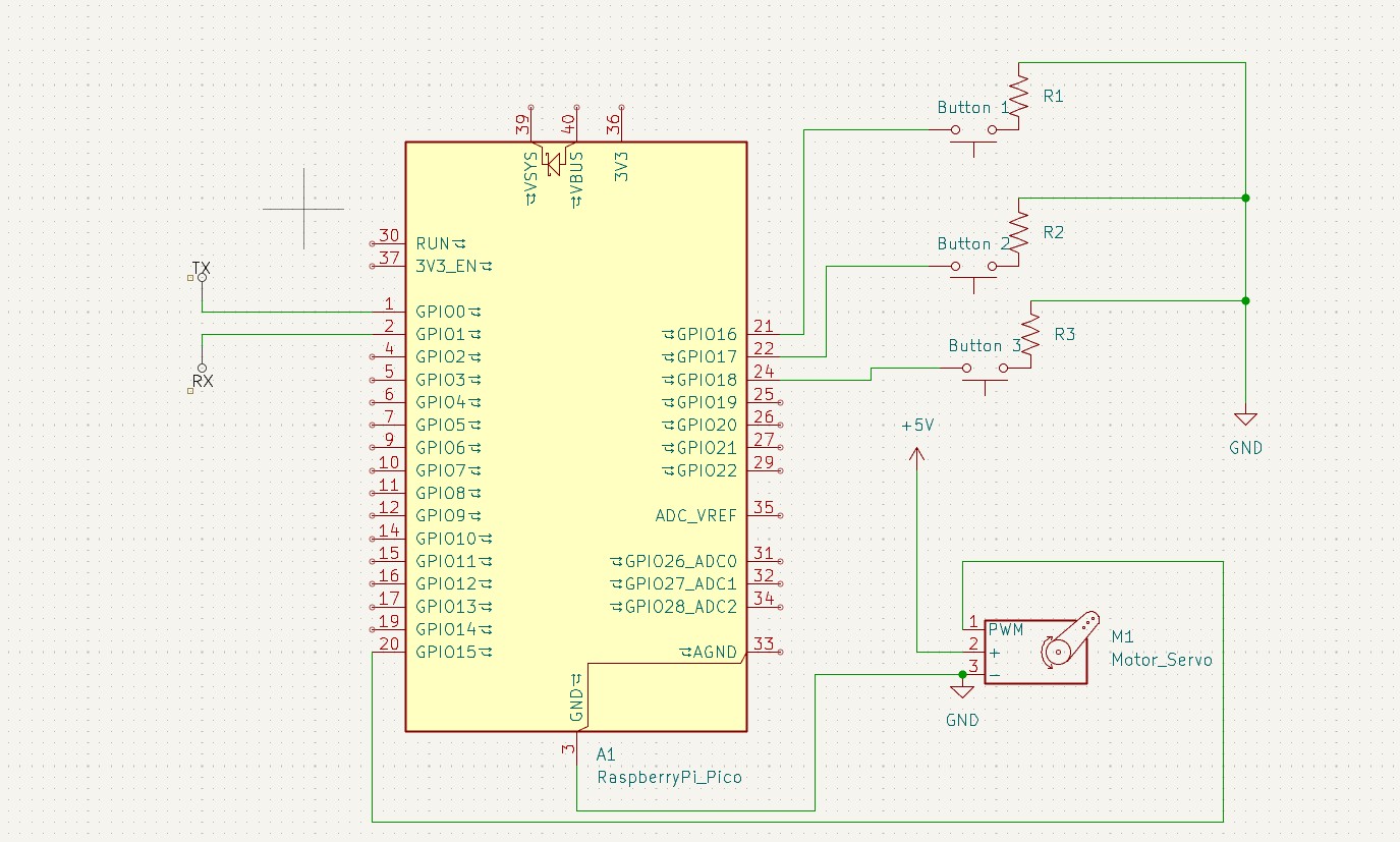
Important: Servo must be powered with 5–6V and share GND with Pico.
Source Code
#include "pico/stdlib.h"
#include "hardware/uart.h"
#include
#include
#include "hardware/pwm.h"
#define UART_ID uart0
#define BAUD_RATE 115200
#define TX_PIN 0
#define RX_PIN 1
#define btn_mode 16
#define btn_next 17
#define btn_prev 18
#define PWM_PIN 0
#define SERVO_PIN 15
using namespace std;
#define list 10

volatile int programa = 0;

uint16_t angle_to_pwm(float angle) {
    float pulse_ms = 1.0f + (angle / 180.0f);   // 1.0 → 2.0 ms
    float duty = (pulse_ms / 20.0f) * 39062.0f; // 20 ms periodo total
    return (uint16_t)duty;
}

// --- Rutina de interrupción ---
static void button_isr(uint gpio, uint32_t events) {
    if (gpio == btn_mode && (events & GPIO_IRQ_EDGE_FALL)) {
        programa++;
        if (programa > 2) {
            programa = 0;
        }
        if (programa == 0) {
            printf("Modo de Escritura Activado\n");
        } else if (programa == 1) {
            printf("Modo de Lectura Activado\n");
        } else if (programa == 2) {
            printf("Modo de Navegacion Activado\n");
        }
        sleep_ms(500);
    }
}

int main() {
    int pos = 0;
    stdio_init_all();
    uart_init(UART_ID, BAUD_RATE);
    uart_set_format(UART_ID, 8, 1, UART_PARITY_NONE);
    gpio_set_function(SERVO_PIN, GPIO_FUNC_PWM);
    uint slice = pwm_gpio_to_slice_num(SERVO_PIN);
    pwm_set_clkdiv(slice, 64.0f);
    pwm_set_wrap(slice, 39062);
    pwm_set_enabled(slice, true);

    int next1 = 0;
    int prev1 = 0;

    // Botones con pull-up interna
    gpio_init(btn_mode);
    gpio_set_dir(btn_mode, GPIO_IN);
    gpio_pull_up(btn_mode);

    gpio_init(btn_next);
    gpio_set_dir(btn_next, GPIO_IN);
    gpio_pull_up(btn_next);

    gpio_init(btn_prev);
    gpio_set_dir(btn_prev, GPIO_IN);
    gpio_pull_up(btn_prev);

    // Interrupción botón modo
    gpio_set_irq_enabled_with_callback(btn_mode, GPIO_IRQ_EDGE_FALL, true, &button_isr);

    string p1 = "";
    int lista[list] = {720, 720, 720, 720, 720, 720, 720, 720, 720, 720};
    int i = -1;

    while (true) {
        int pos = 0;

        if (programa == 0) {
            int ch = getchar_timeout_us(0);
            if (ch != PICO_ERROR_TIMEOUT) {

                if (ch == ',') {
                    if (p1 == "Escribir" || p1 == "write" || p1 == "WRITE" || p1 == "escribir" || p1 == "Write" || p1 == "ESCRIBIR") {
                        p1 = "";
                        int contador = 0;
                        for (int k = 0; k < list; k++) {
                            if (lista[k] != 720) {
                                contador++;
                            }
                        }
                        if (contador == list) {
                            printf("Lista llena, no se pueden agregar mas elementos.\n");
                            p1 = "";
                            continue;
                        } else {
                            i++;
                            while (ch != ';' && ch != '\n') {
                                ch = getchar_timeout_us(0);
                                if (ch != PICO_ERROR_TIMEOUT) {
                                    if (ch == ',') {
                                        printf("Eco: %s\n", p1.c_str());
                                        if (stoi(p1) > 180 || stoi(p1) < 0) {
                                            printf("Valor fuera de rango (0-180). Intente de nuevo.\n");
                                            i--;
                                        } else {
                                            lista[i] = stoi(p1);
                                            i++;
                                            p1 = "";
                                        }
                                    } else if (ch == ';' || ch == '\n') {
                                        if (stoi(p1) > 180 || stoi(p1) < 0) {
                                            printf("Valor fuera de rango (0-180). Intente de nuevo.\n");
                                            i--;
                                        } else {
                                            lista[i] = stoi(p1);
                                            p1 = "";
                                        }
                                    } else {
                                        p1 += (char)ch;
                                    }

                                    printf("Lista: ");
                                    for (int k = 0; k <= i; ++k) {
                                        printf("%d", lista[k]);
                                        if (k + 1 <= i) printf(", ");
                                    }
                                    printf("\n");
                                }
                            }
                        }
                    }
                }

                if (ch == ';' || ch == '\n') {
                    if (p1 == "Borrar" || p1 == "delete" || p1 == "DELETE" || p1 == "borrar" || p1 == "BORRAR") {
                        for (int k = 0; k < list; k++) lista[k] = 720;
                        i = -1;
                        printf("Ok, Lista borrada\n");
                    }
                    p1 = "";
                } else {
                    p1 += (char)ch;
                }
            }
        } else if (programa == 1) {
            while (programa == 1) {
                int contador = 0;
                for (int k = 0; k < list; k++) {
                    if (lista[k] != 720) contador++;
                }
                if (contador == 0) {
                    printf("La lista esta vacia. Cambie al modo de escritura.\n");
                    sleep_ms(1500);
                } else {
                    int j = 0;
                    while (programa == 1 && j < contador) {
                        printf("posicion: %d , valor: %d\n", j, lista[j]);
                        pwm_set_gpio_level(SERVO_PIN, angle_to_pwm(lista[j]));
                        printf("Angulo: %.1f°\n", lista[j]);
                        sleep_ms(1500);
                        j++;
                    }
                }
            }
        } else if (programa == 2) {
            while (programa == 2) {
                static int i = 0;
                const int LISTA_LEN = 10;

                if (lista[pos] == 720) pos--;
                int contador = 0;
                for (int k = 0; k < list; k++) if (lista[k] != 720) contador++;

                if (next1 == 0 && gpio_get(btn_next) == 1) {
                    if (contador == 0 && gpio_get(btn_next) == 1) {
                        printf("Lista Vacia, no se puede avanzar.\n");
                        sleep_ms(100);
                    } else {
                        pos++;
                        printf("siguiente \n");
                        if (lista[pos] == 720) {
                            printf("Valor no valido, regresando a %d\n", pos - 1);
                            pos--;
                        }
                        if (pos == list) pos = 0;
                        printf("posicion: %d , valor: %d\n", pos, lista[pos]);
                        pwm_set_gpio_level(SERVO_PIN, angle_to_pwm(lista[pos]));
                        printf("Angulo: %.1f°\n", lista[pos]);
                        sleep_ms(200);
                    }
                }
                next1 = gpio_get(btn_next);

                if (prev1 == 0 && gpio_get(btn_prev) == 1) {
                    if (contador == 0 && gpio_get(btn_prev) == 1) {
                        printf("Lista Vacia, no se puede avanzar.\n");
                        sleep_ms(100);
                    } else {
                        pos--;
                        printf("anterior \n");
                        if (pos == -1) {
                            printf("Valor no valido, regresando a %d\n", pos + 1);
                            pos++;
                        }
                        if (pos == list) pos = 0;
                        printf("posicion: %d , valor: %d\n", pos, lista[pos]);
                        pwm_set_gpio_level(SERVO_PIN, angle_to_pwm(lista[pos]));
                        printf("Angulo: %.1f°\n", lista[pos]);
                        sleep_ms(200);
                    }
                }
                prev1 = gpio_get(btn_prev);
            }
        }
    }
    return 0;
}
Detailed Code Explanation
Internal architecture and operation logic of the Servo Angle List system.
1. System Architecture
The program implements a small state machine controlled by an interrupt-driven button.
The global variable programa defines the active mode:
- 0 → Write Mode
- 1 → Read Mode
- 2 → Navigation Mode
The system continuously runs inside the main while(true) loop,
executing different behaviors depending on the current mode.
2. PWM Configuration (Servo Control)
Standard hobby servos operate at approximately 50 Hz (20 ms period).
pwm_set_clkdiv(slice, 64.0f);
pwm_set_wrap(slice, 39062);
These values generate a 20 ms PWM period. The servo position is determined by varying the pulse width between:
- 1.0 ms → 0°
- 1.5 ms → 90°
- 2.0 ms → 180°
Angle Conversion Function
uint16_t angle_to_pwm(float angle)
Converts an angle (0–180°) into the corresponding PWM duty cycle.
Internally:
pulse_ms = 1.0 + (angle / 180)
duty = (pulse_ms / 20 ms) × 39062
This ensures a linear mapping between angle and servo position.
3. Mode Switching via Interrupt
The mode button (GPIO 16) is configured with:
gpio_set_irq_enabled_with_callback(...)
When a falling edge is detected (button pressed),
the interrupt routine button_isr() executes.
- Increments
programa - Cycles 0 → 1 → 2 → 0
- Prints active mode to console
The 500 ms delay inside the ISR acts as a basic debounce, although best practice would move debounce logic outside the interrupt.
4. Write Mode (programa == 0)
In this mode, the system listens to UART input using:
getchar_timeout_us(0)
This allows non-blocking serial reading.
Supported Commands
- Escribir,90,120,45; → Stores angles
- Borrar; → Clears list
The list can store up to 10 values.
The value 720 represents an empty slot.
Validation
- Values must be between 0 and 180
- If invalid → error message is printed
- List overflow is prevented
After each insertion, the updated list is printed to the console.
5. Read Mode (programa == 1)
In this mode, the servo automatically plays back all stored angles.
- Counts valid elements in list
- Iterates sequentially
- Moves servo every 1.5 seconds
pwm_set_gpio_level(SERVO_PIN, angle_to_pwm(lista[j]));
If the list is empty, the system prints a warning message.
6. Navigation Mode (programa == 2)
In this mode, the servo position is manually controlled using:
- Next Button (GPIO 17)
- Previous Button (GPIO 18)
Logic
- Detects button edge transitions
- Updates index position
- Wraps around list boundaries
- Skips invalid entries (value 720)
This allows interactive browsing through stored angles.
7. UART Communication
Configured at:
115200 bps
8 data bits
No parity
1 stop bit (8N1)
Even though UART0 is initialized on GPIO 0 and 1, stdio is available via USB CDC, allowing direct use of the serial monitor without external TX/RX wiring.
8. Memory Management Strategy
The list is implemented as:
int lista[10]
Using a fixed-size array simplifies memory usage, avoids dynamic allocation, and ensures deterministic behavior — important in embedded systems.
9. System Behavior Summary
| Mode | Function | Interaction |
|---|---|---|
| Write | Stores angles via UART | Serial console |
| Read | Automatic playback | Autonomous |
| Navigation | Manual control | Physical buttons |
10. Key Embedded Concepts Demonstrated
- Interrupt-driven state switching
- Non-blocking UART parsing
- Edge detection with GPIO
- Software validation of input data
- Deterministic memory allocation
- PWM timing for servo control