CAD Tools Comparison

In Week 2, I documented the workflow and results of 2D vectorization and 3D modeling using different tools, focusing on speed, control, and usability.

2D Bitmap → Vector

Inkscape vs Affinity Designer

I used the same raster image (bitmap) and converted it into a vector file using two different tools. The goal was to compare automatic vectorization (Inkscape) versus manual tracing (Affinity Designer).

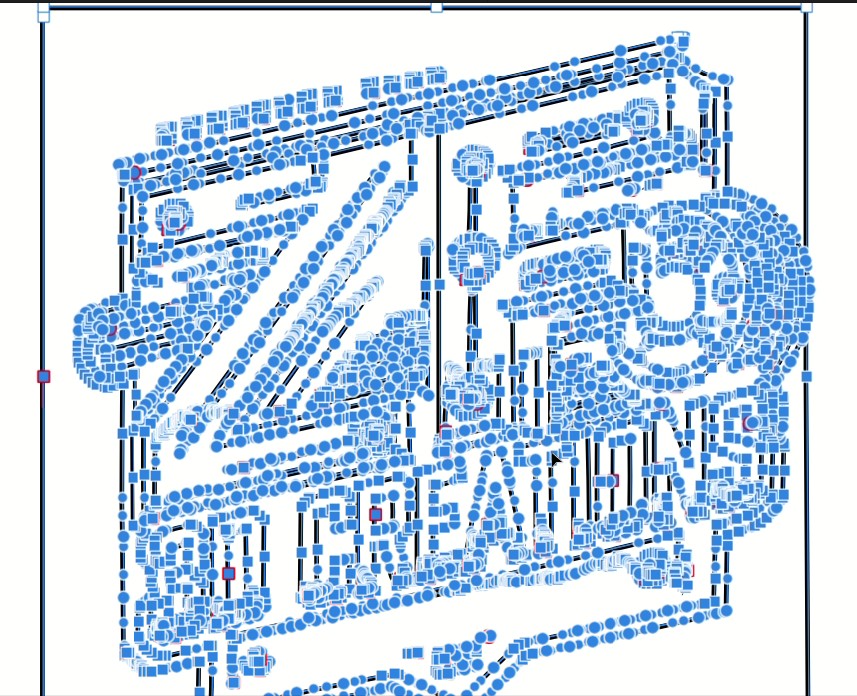
Inkscape (Automatic workflow)

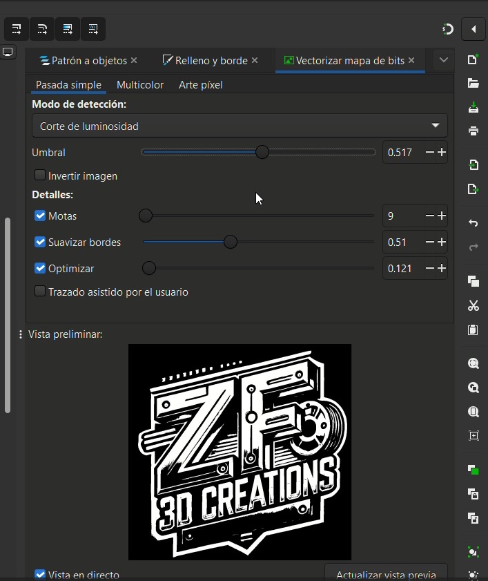
In Inkscape, the process is mostly automated using Path → Trace Bitmap. The software analyzes the bitmap and generates vector paths based on a threshold (brightness cutoff).

Step-by-step
  1. Select the image on the canvas.
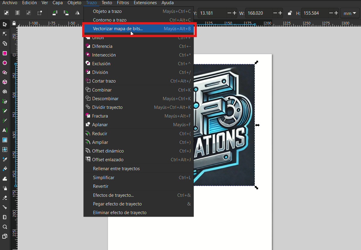
  2. Go to Path → Trace Bitmap.
  3. Use Brightness cutoff and adjust the threshold until the preview looks clean.
  4. Click Apply to generate the vector.
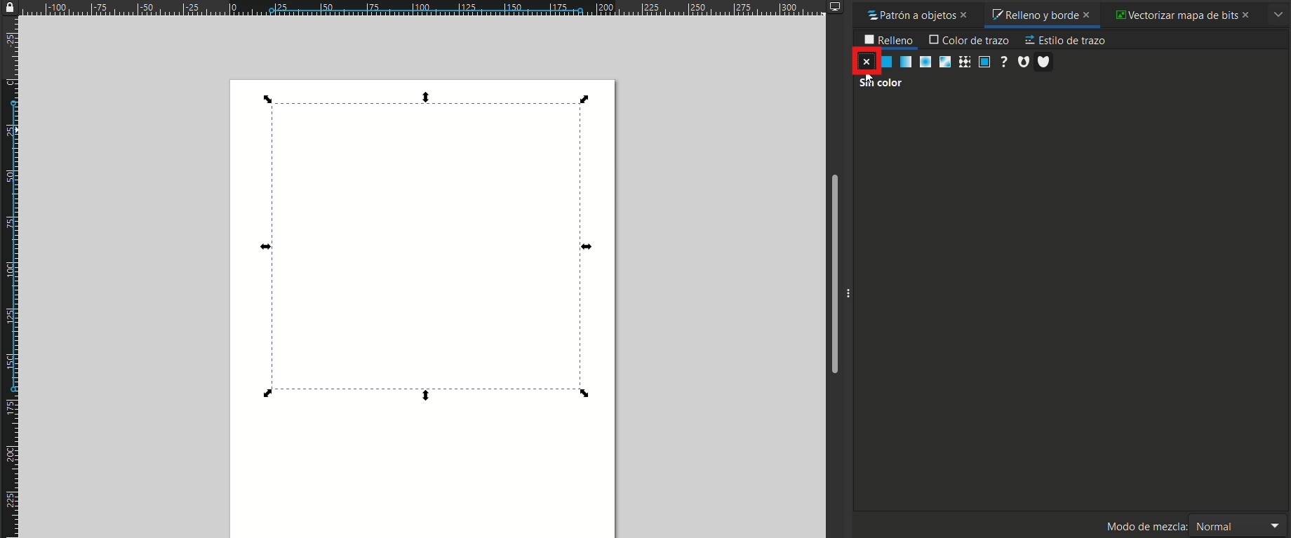
  5. Remove fill / set stroke if needed to verify the outline.
Inkscape menu Path → Trace Bitmap
Inkscape: Path → Trace Bitmap (Vectorize Bitmap).
Trace Bitmap panel showing threshold settings
Trace Bitmap panel: brightness cutoff + threshold tuning (live preview).
Vector result after applying Trace Bitmap
Result: vector generated automatically on top of the original bitmap.
Fill and Stroke panel to remove fill and set stroke
Fill & Stroke: removing fill / enabling stroke to inspect the paths.
Final clean vector outline in Inkscape
Final outline check: clean paths ready for fabrication export (SVG/DXF/PDF).

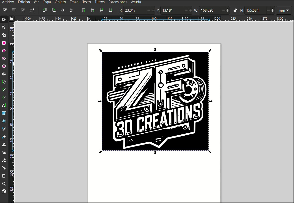
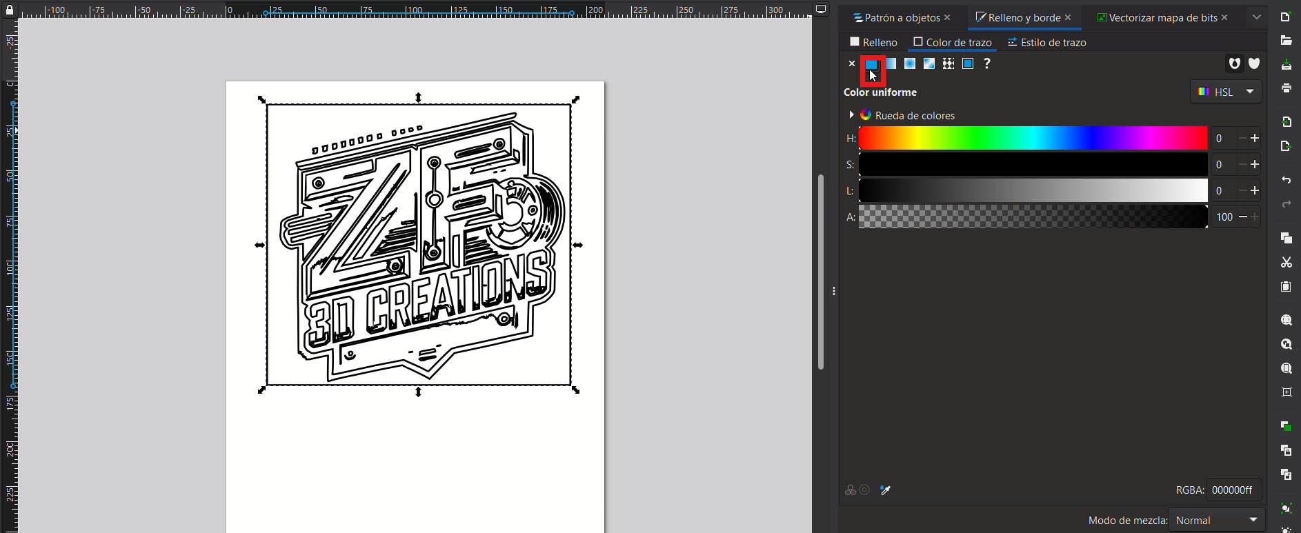
Conclusion (Inkscape): Fast and efficient for high-contrast images and fabrication-ready vectors. The main tradeoff is less control over fine details compared to a fully manual workflow.

Download .SVG

Affinity Designer (Manual workflow)

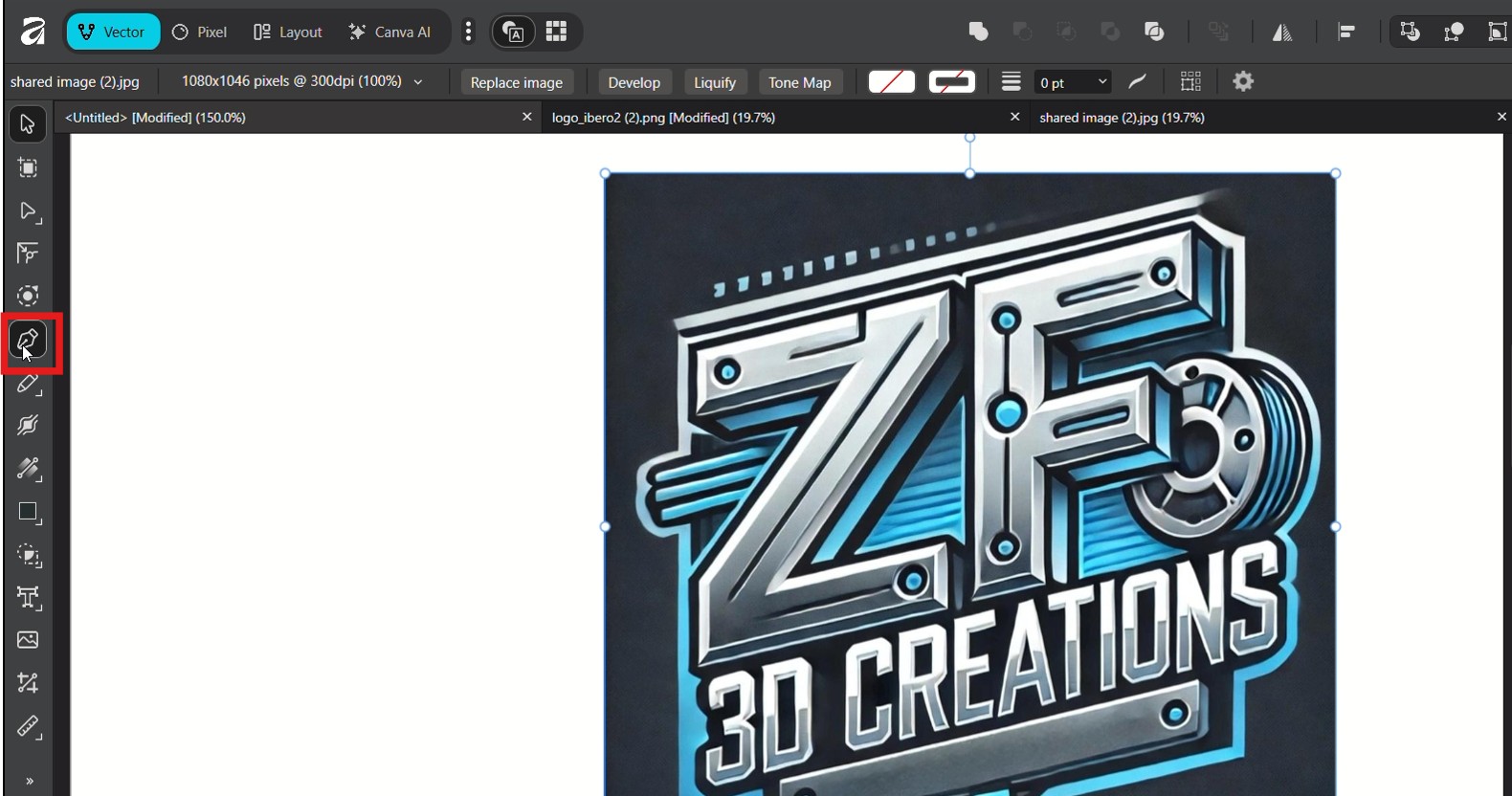
In Affinity Designer, the vectorization was done manually. Instead of a one-click bitmap trace, I placed the image and recreated the contours using vector tools (Pen/Node). This takes more time, but gives full control over geometry.

Step-by-step
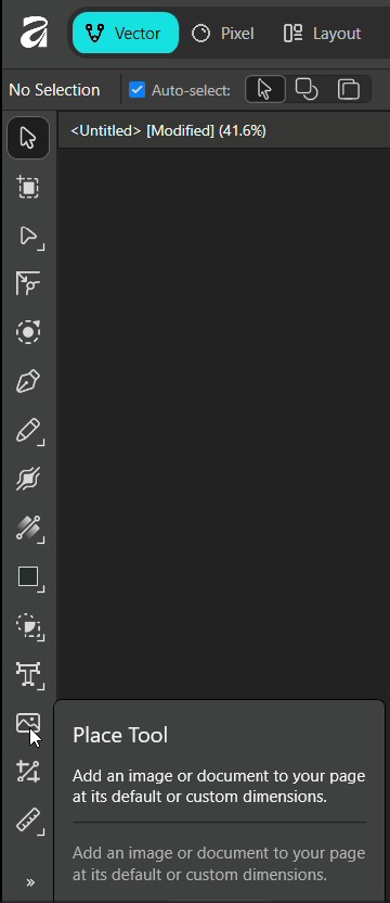
  1. Use the Place Tool to import the bitmap image.
  2. Work in Vector mode (not Pixel mode).
  3. Trace the main contours using the Pen Tool.
  4. Refine curves and corners with the Node Tool.
  5. Adjust stroke/fill to verify clean outlines and remove unnecessary nodes.
Affinity Designer interface showing Place Tool
Affinity: Place Tool used to import the raster image.
Affinity Designer showing the Pen Tool selected
Tracing started with the Pen Tool (manual creation of paths).
Affinity Designer showing a traced contour on top of the image
Manual contour tracing: nodes and curves placed directly over the bitmap.
Affinity vector artwork with many nodes visible
Node editing and refinement: full control over each curve and detail.
Final vector result in Affinity
Final result: clean vector lines generated through manual tracing.

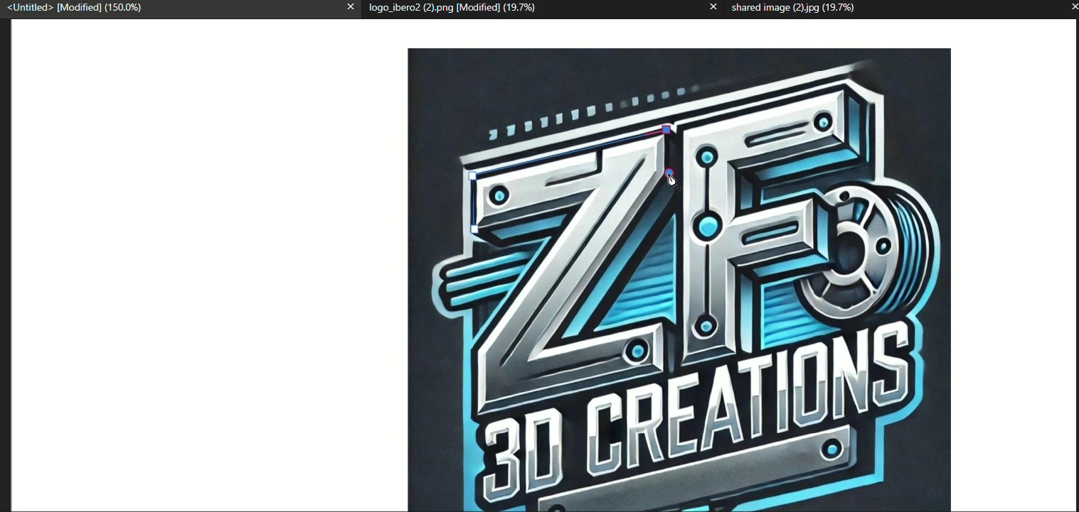
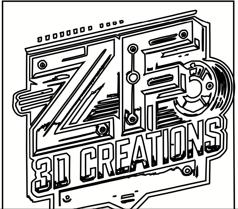
Conclusion (Affinity): Slower than Inkscape but offers higher precision and cleaner geometry, especially for complex shapes or when you need full control over the final vector.

Download .af
“Inkscape prioritizes speed (automatic trace), while Affinity prioritizes precision (manual control).”
3D Parametric CAD

SolidWorks vs OnShape — Parametric Modeling Workflow

For the 3D modeling assignment, I designed two different mechanical parts using SolidWorks and OnShape. The objective was not only to model the parts, but also to understand how each software handles parametric design, feature history, and user interaction.

SolidWorks (Preferred tool)

SolidWorks is a feature-based parametric CAD software widely used in mechanical engineering. I prefer it because I am certified in SolidWorks and I find its workflow more intuitive and structured.

Interface and main components
  • Feature Tree: Shows the complete modeling history (sketches, extrudes, cuts, fillets).
  • Graphics Area: Where the 3D geometry is visualized.
  • Command Manager: Toolbar with sketch and feature operations.
SolidWorks interface and final model
SolidWorks interface showing the feature tree and final model.
Modeling workflow (step-by-step)
  1. Sketch: A 2D sketch is created on a reference plane (Front, Top, or Right). Dimensions and constraints define the geometry precisely.
  2. Extrude: The sketch is converted into a 3D solid by adding material. Used to create the main body of the part.
  3. Cut-Extrude: Removes material from the solid. Commonly used for holes, slots, or internal features.
  4. Fillet / Chamfer: Adds rounded or beveled edges to improve strength, aesthetics, and manufacturability.
  5. Parametric editing: Any dimension can be modified later, and the entire model updates automatically.

Key advantage: The linear feature tree makes it very easy to debug, edit, and understand how the model was built. This is especially useful for mechanical parts and assemblies.

Download .SLDPRT

OnShape (Cloud-based CAD)

OnShape is a fully cloud-based parametric CAD platform that runs in a web browser. It offers many similar tools to SolidWorks but with a different philosophy focused on collaboration.

Interface and main components
  • Feature List: Similar to a feature tree, displayed at the bottom.
  • Graphics Area: Browser-based 3D viewport.
  • Toolbar: Context-based tools for sketching and modeling.
OnShape interface and final model
OnShape interface showing the modeled part in the browser.
Modeling workflow (step-by-step)
  1. Sketch: Similar to SolidWorks, sketches are created on planes with dimensions and constraints.
  2. Extrude / Remove: Used to add or remove material from the sketch. Operations are very similar in concept to SolidWorks.
  3. Fillet / Chamfer: Used to refine edges and corners for functional or aesthetic purposes.
  4. Timeline-based editing: Features can be edited, but navigating the history feels less linear compared to SolidWorks.

Main difference: OnShape excels at real-time collaboration and version control, but I personally found the interface less intuitive for fast mechanical design.

See in OnShape
“Both tools use parametric design, but SolidWorks prioritizes a structured mechanical workflow, while OnShape focuses on accessibility and collaboration.”

Video Compression with FFmpeg

Reducing video size for faster uploads and smoother documentation performance.

For documentation, I recorded a short demonstration explaining how to compress videos using FFmpeg. This helps reduce file size while keeping acceptable visual quality for web uploads.

Command used

ffmpeg -i FFMPEG.mp4 -vf "scale=-2:720" -c:v libx264 -preset slow -crf 30 -pix_fmt yuv420p -movflags +faststart -an FFMPEGcomp.mp4

What each option does

  • -i FFMPEG.mp4: Input video
  • -vf "scale=-2:720": Resize to 720p while keeping aspect ratio
  • -c:v libx264: Encode using H.264 (widely compatible)
  • -preset slow: Better compression efficiency (takes longer)
  • -crf 30: Controls quality vs size (higher = smaller file)
  • -pix_fmt yuv420p: Maximum device/browser compatibility
  • -movflags +faststart: Enables faster web playback (moov atom at beginning)
  • -an: Removes audio (optional, reduces size)

Video demonstration

For local MP4 files, using a <video> tag is more reliable than an iframe.

FFmpeg tutorial video (compressed version).

Photo Compression with Inkscape

Reducing photo size for faster uploads and smoother documentation performance, also it helps with the memory space used on the website.

What i did to compress the photos was to open the image in Inkscape and then export it as a PNG, then reduce the DPI, this way i could reduce the size of the image without losing much quality, also i could adjust the resolution to make it smaller.

Inkscape for compression