Wildcard week - Assignment:
The objective of the Wildcard Week is to explore a fabrication digital method, tool, or process that has not been covered in the previous weeks of the Fab Academy program. This week provides the opportunity to experiment with diverse manufacturing workflows such as composites, textiles, food printing, or advanced craft automation.
For my project, I decided to dive into digital fabrication for textiles, specifically focusing on computerized embroidery. To achieve this, I utilized Inkscape as my primary vector design software, augmented by InkStitch, an open-source machine embroidery extension. This toolchain allows the translation of vector graphics into precise machine paths, stitch types, and standard embroidery formats required by industrial or semi-professional embroidery machines.
Vector Design & Image Preparation
Before generating any embroidery stitch patterns inside InkStitch, a pristine vector structure must be established. Machine embroidery requires highly defined, non-overlapping vector paths with clear color definitions to understand the sewing order. The following workflow outlines the digital preparation in Inkscape.
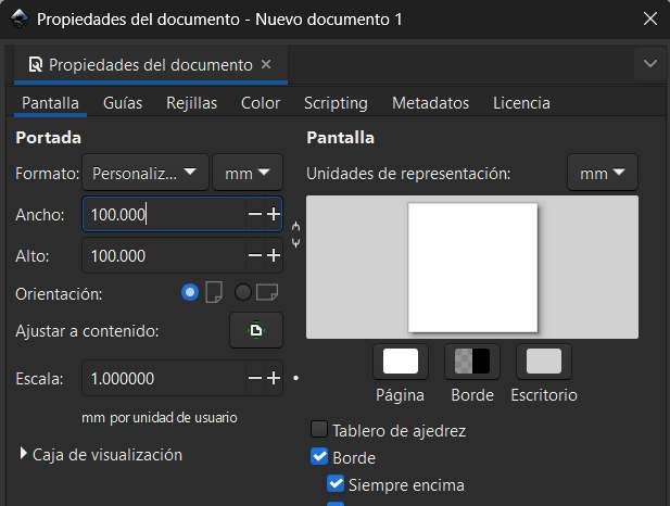
1. Launch Inkscape: Start the software and prepare the workspace for the embroidery design by setting the document properties to a 100x100 mm canvas, which represents the maximum embroidery area used for this project.
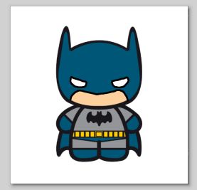
2. Import Image: Import the reference raster artwork (PNG or JPG format) into the canvas.
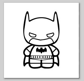
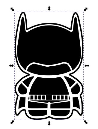
3. Trace Bitmap: Vectorize the imported image using the Path > Trace Bitmap tool to generate scalable vector geometries from the pixels.
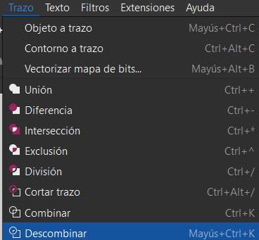
4. Break Apart Paths: Use the Path > Break Apart function to separate complex, combined shapes into individual vector elements.
5. Adjust Stroke and Fill: Select the topmost layer, remove its solid fill color, and leave only the stroke to clearly define the outlines.
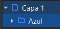
6. Color Assignment: Navigate to the layers panel and systematically assign specific colors to each vector path to match the physical thread palette.
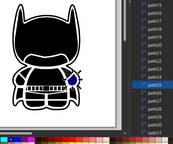
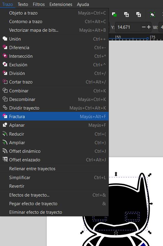
7. Path Fracture: In cases where separate elements are digitally fused (such as overlapping eyes within a mask background in my design), execute Path > Fracture to effectively split them.
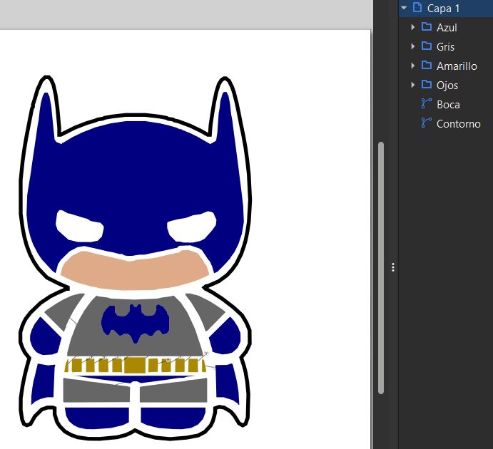
8. Group by Color: Finally, organize and group the vector paths into distinct layers based on their color to streamline the embroidery machine's runtime sequence.
Ink/Stitch Parameterization & Simulation Workflow
With the vector graphics fully prepared and grouped by color, the next phase involves assigning specific embroidery parameters (such as stitch type, spacing, and density) and optimizing the sewing path to prevent messy jump threads.
1. Select Target Layer: Open the Layers panel and select the specific color-grouped vector path you want to program.
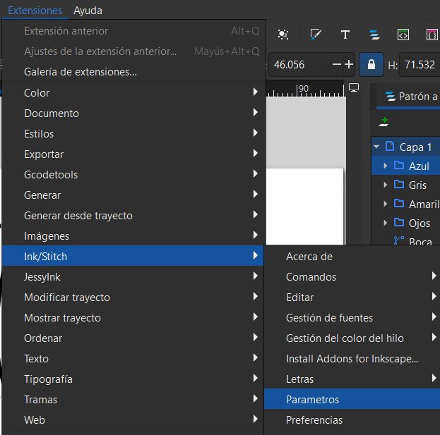
2. Access Stitch Parameters: Navigate to the top menu and select Extensions > Ink/Stitch > Params to configure the path properties.
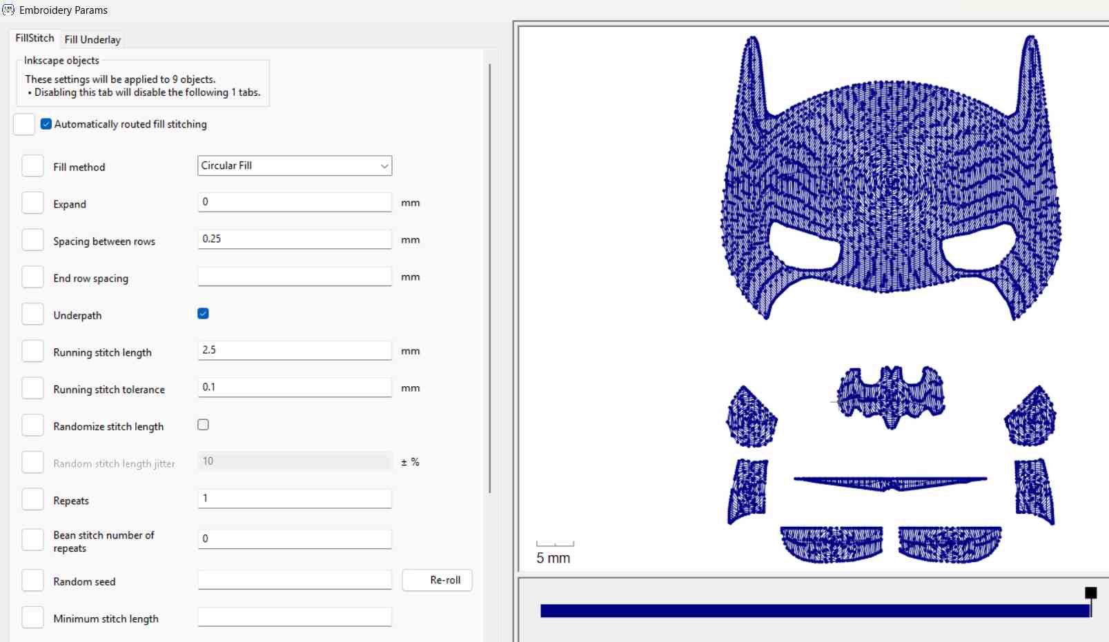
3. Stitch Customization: A modal configuration window will appear alongside a real-time preview. Here, you can adjust the embroidery stitch type (e.g., satin column, fill stitch), pattern layouts, and stitch density.
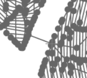
4. Identifying Jump Stitches: Analyze the preview generation. If the machine path forces the needle to move across unrelated sections, it creates a long, undesirable "jump stitch" thread floating over the design.
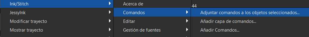
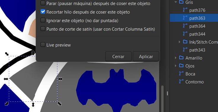
5. Injecting Trim Commands: To force the machine to automatically cut the thread before moving, go to Extensions > Ink/Stitch > Commands > Attach Command to Selected Objects and enable the jump stitch trim command.
6. Target Selection & Application: Select the exact node or path element where the thread jump occurs, configure the execution parameters, and click Apply.
7. Complete Visual Verification: To review the entire optimized sequence, run the full environment tool by selecting Extensions > Ink/Stitch > Visualize and Export > Simulator.
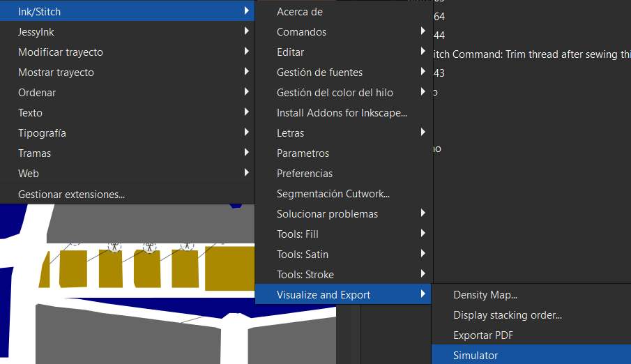
This is my final simulation, displaying a clean execution path with all automated trim cuts perfectly integrated into the digital machine file:
Physical Fabrication: Brother Embroidery Machine Setup
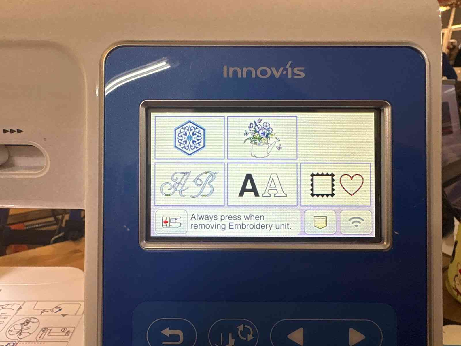
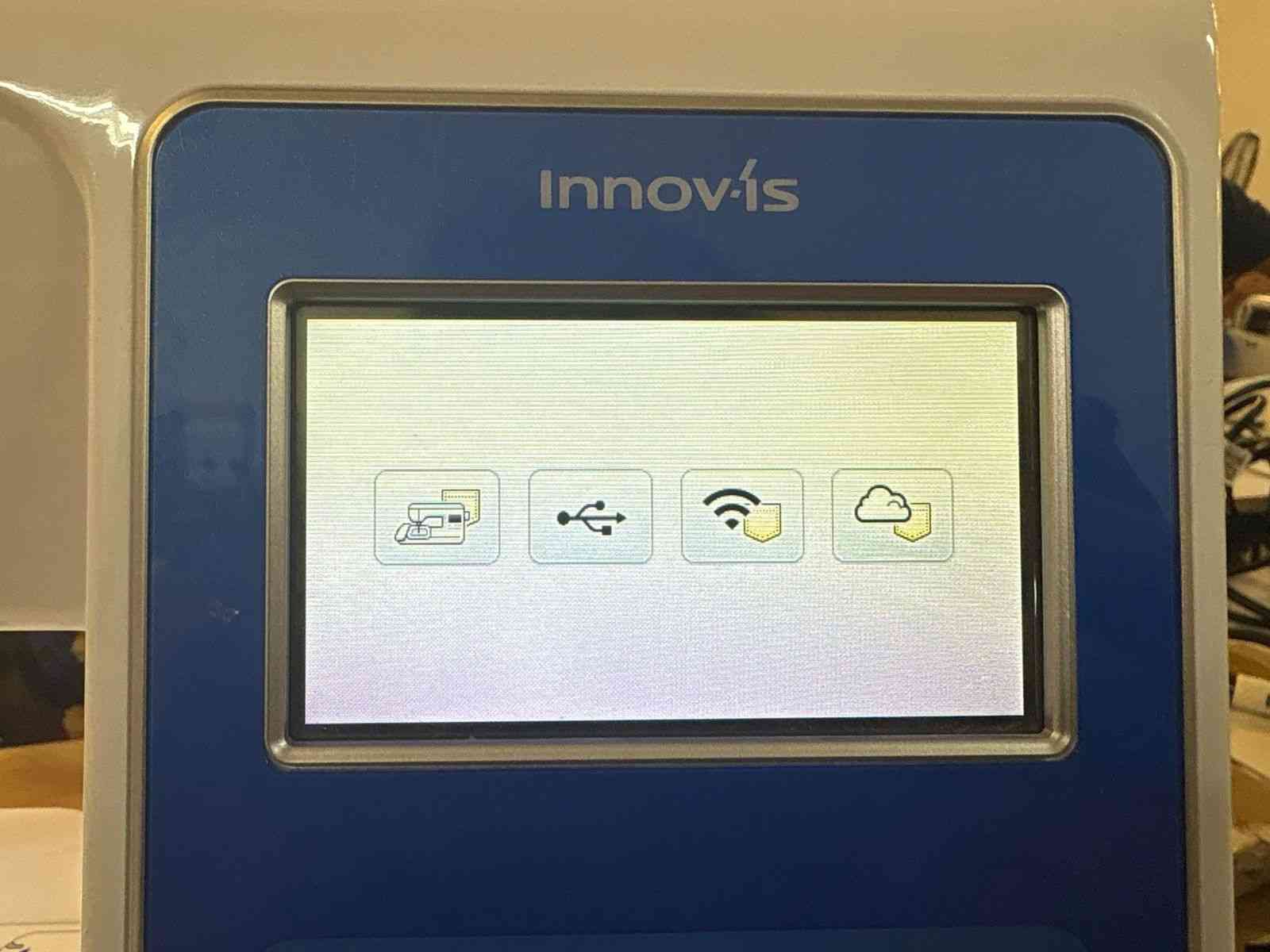
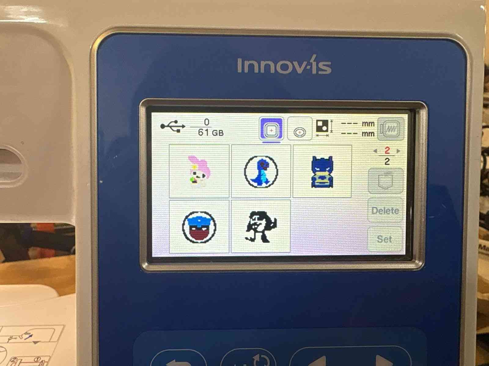
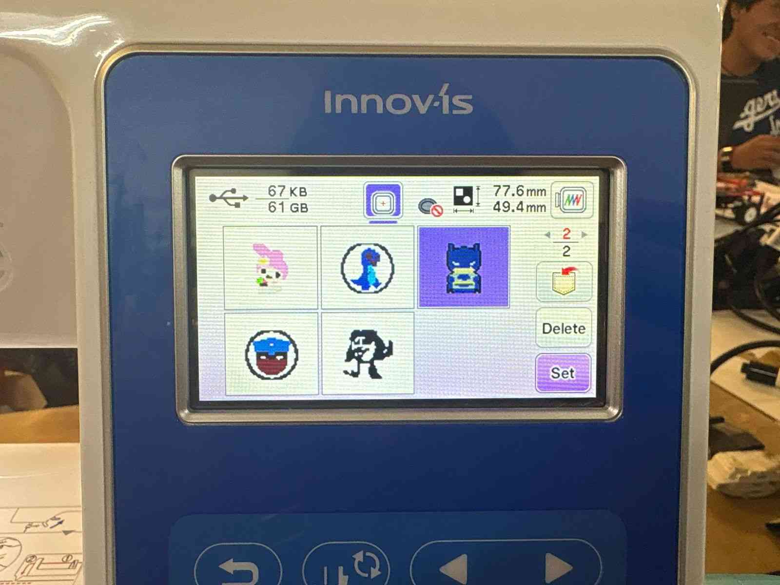
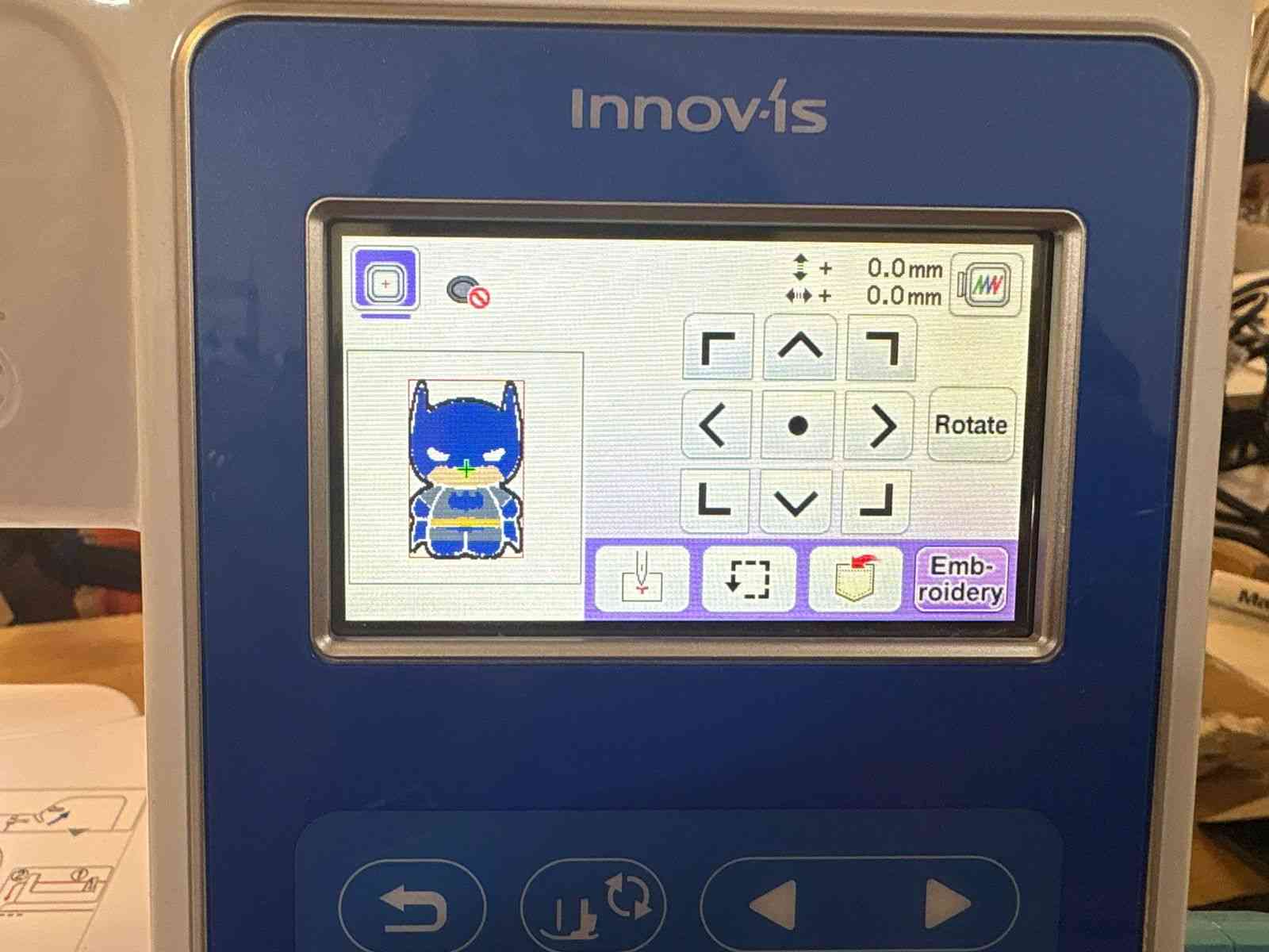
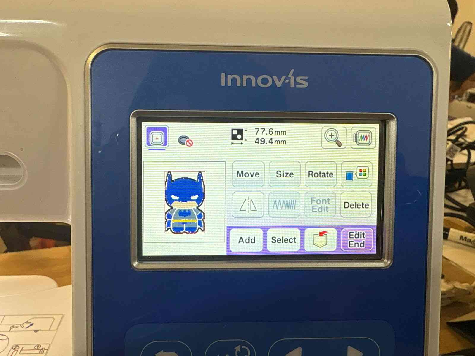
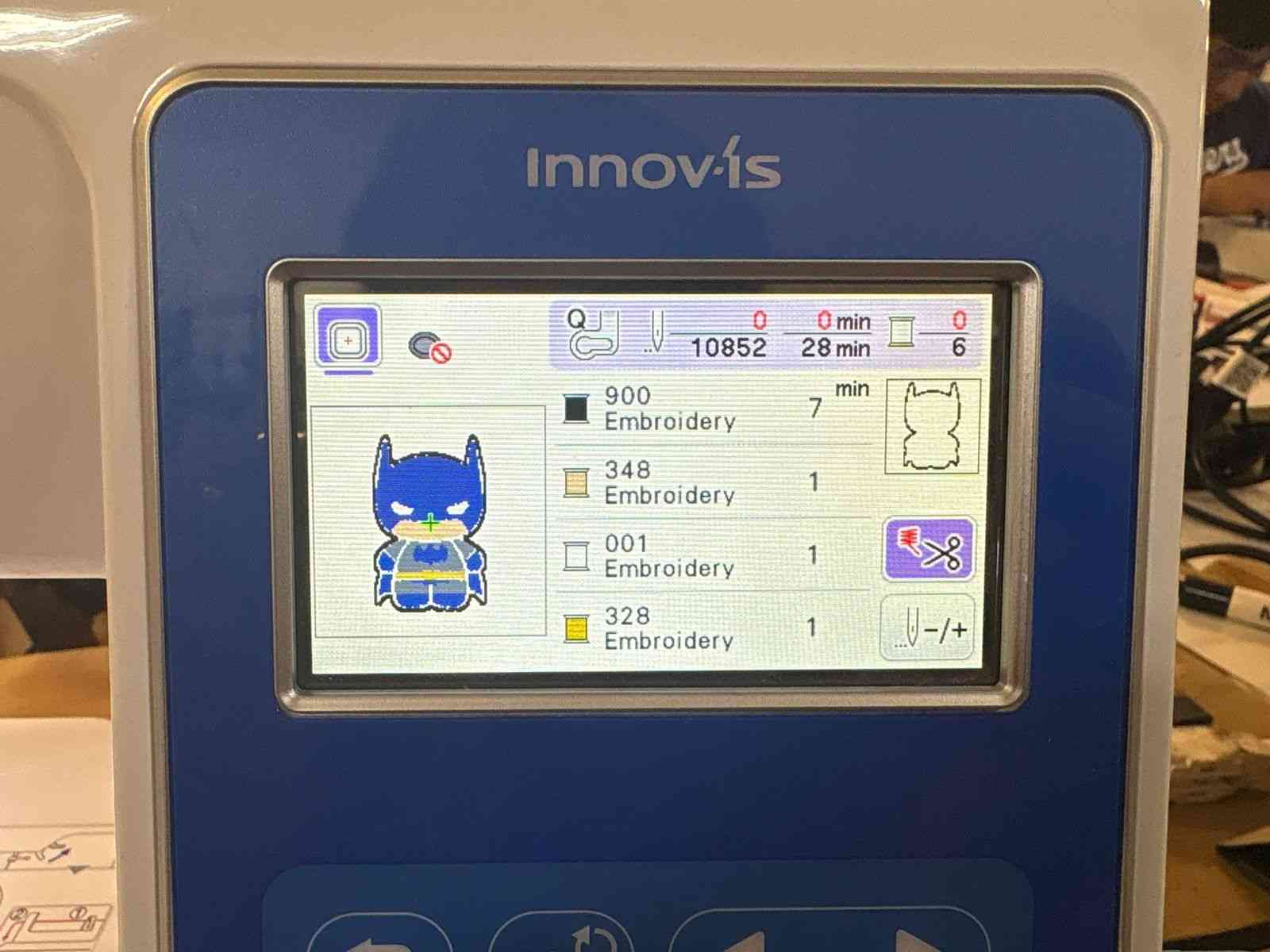
With the digital simulation verified, the final file must be exported from Ink/Stitch as a .pes file, which is the proprietary format recognized by Brother embroidery machines. Next, the fabric is prepared by securing and stretching it tightly across the embroidery hoop to prevent wrinkling. Finally, power on the machine, insert the USB flash drive containing the file, and follow the on-screen interface steps to load the design.
Threading and Starting the Embroidery Process
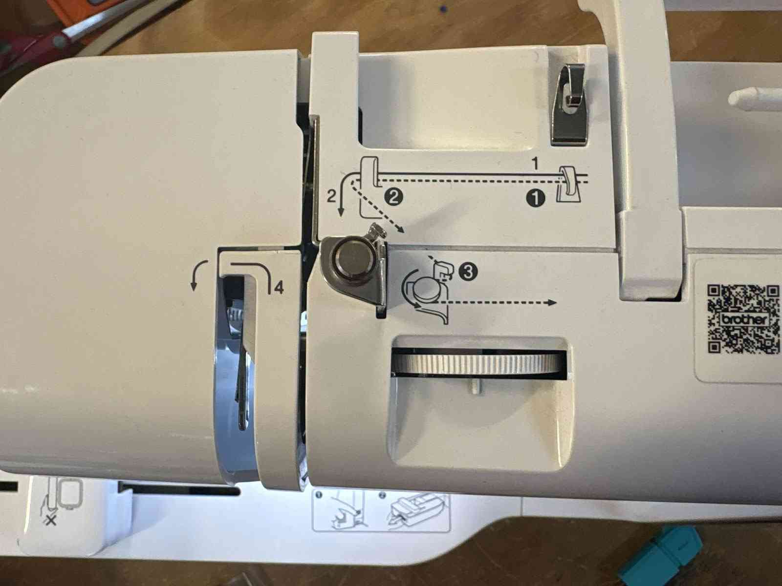
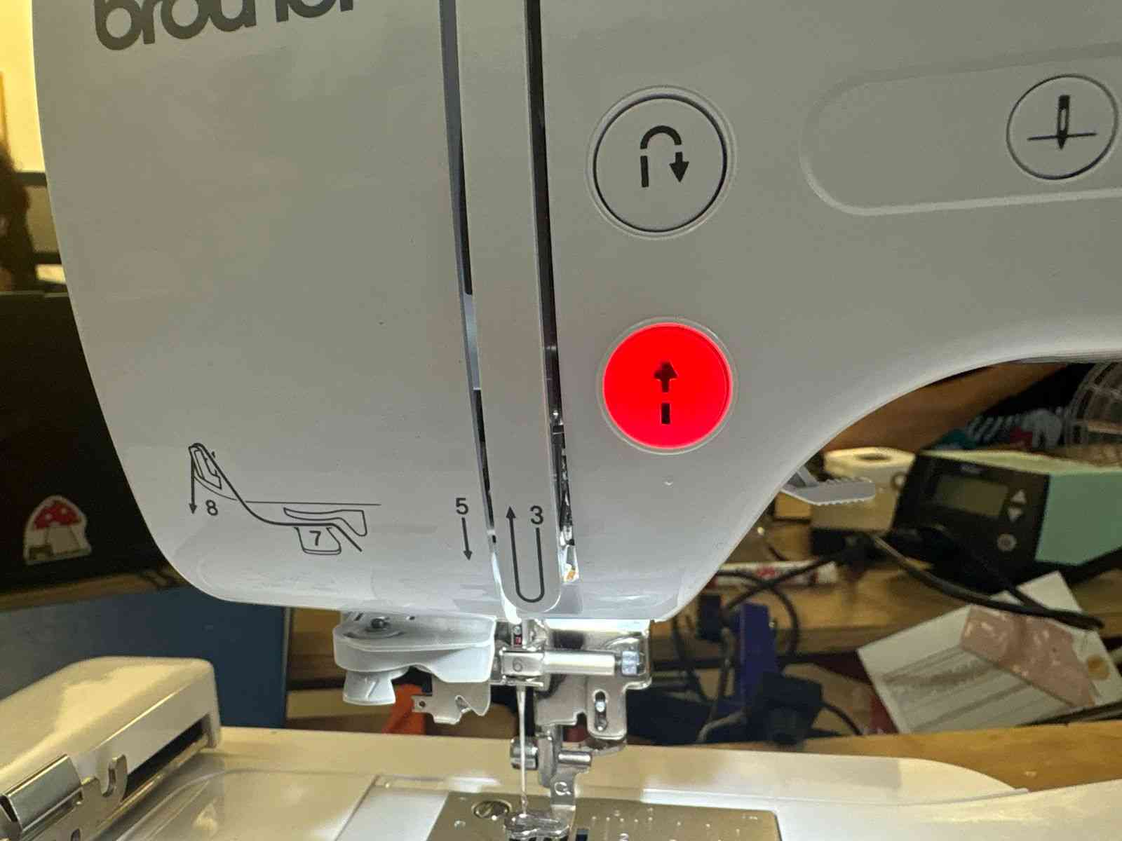
To begin the embroidery process, load the desired thread color by carefully following the numbered routing paths marked directly on the machine's body.
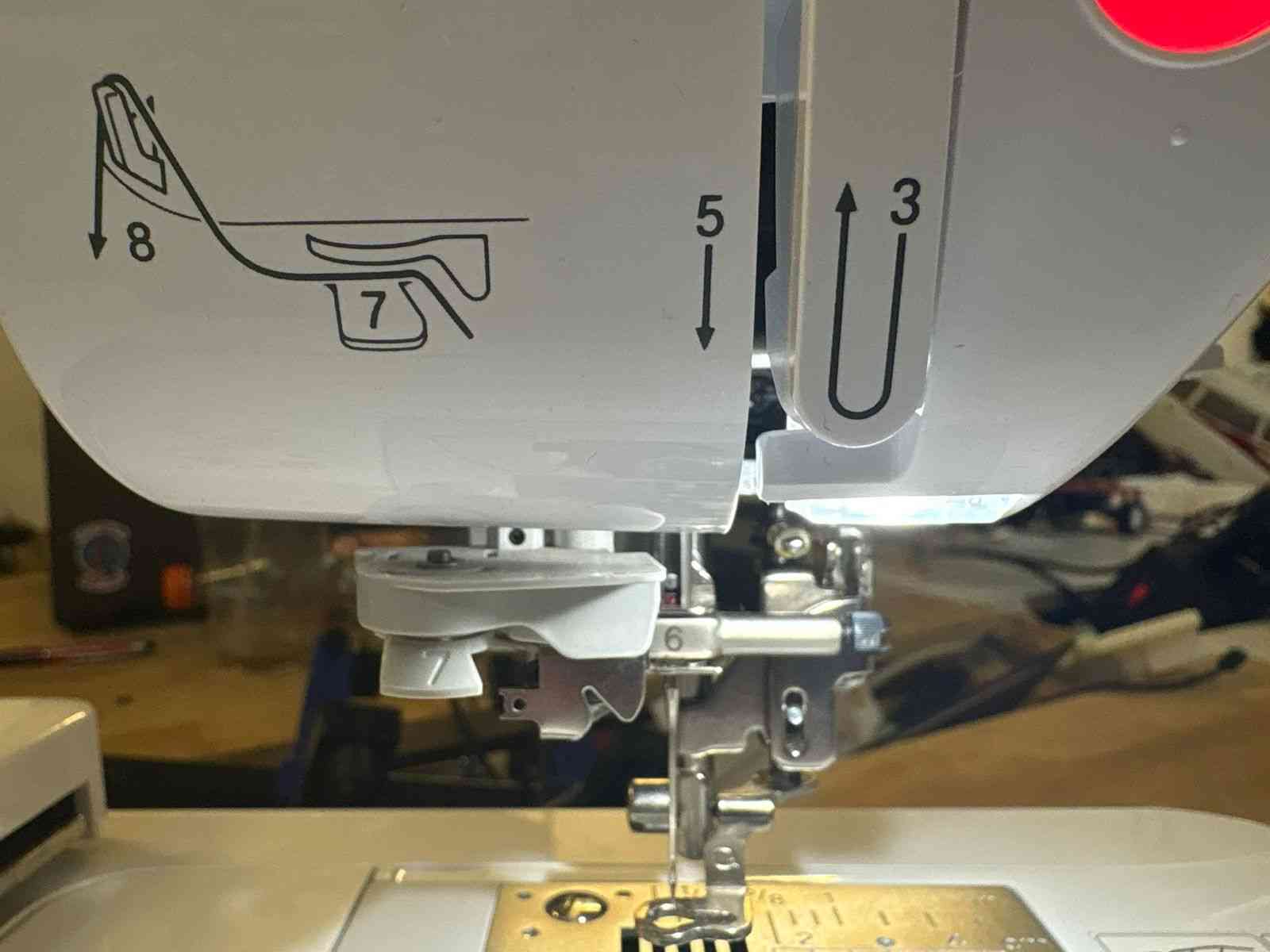
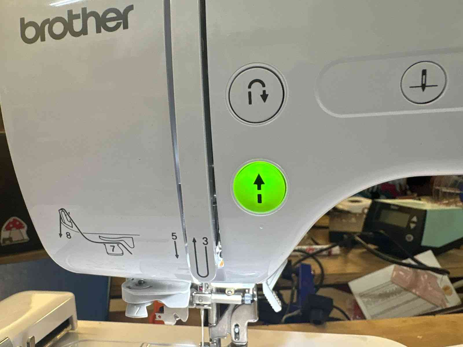
Once the needle is threaded and everything is set, lower the presser foot using the side lever. The start/stop button will illuminate green, indicating the machine is ready. Press it to initiate the embroidery run.
Fabrication in Action & Final Result
With the machine fully prepared and the start sequence initiated, the physical fabrication begins. The video below demonstrates the Brother embroidery machine actively executing the optimized toolpaths, seamlessly translating the digital vector design into thread.
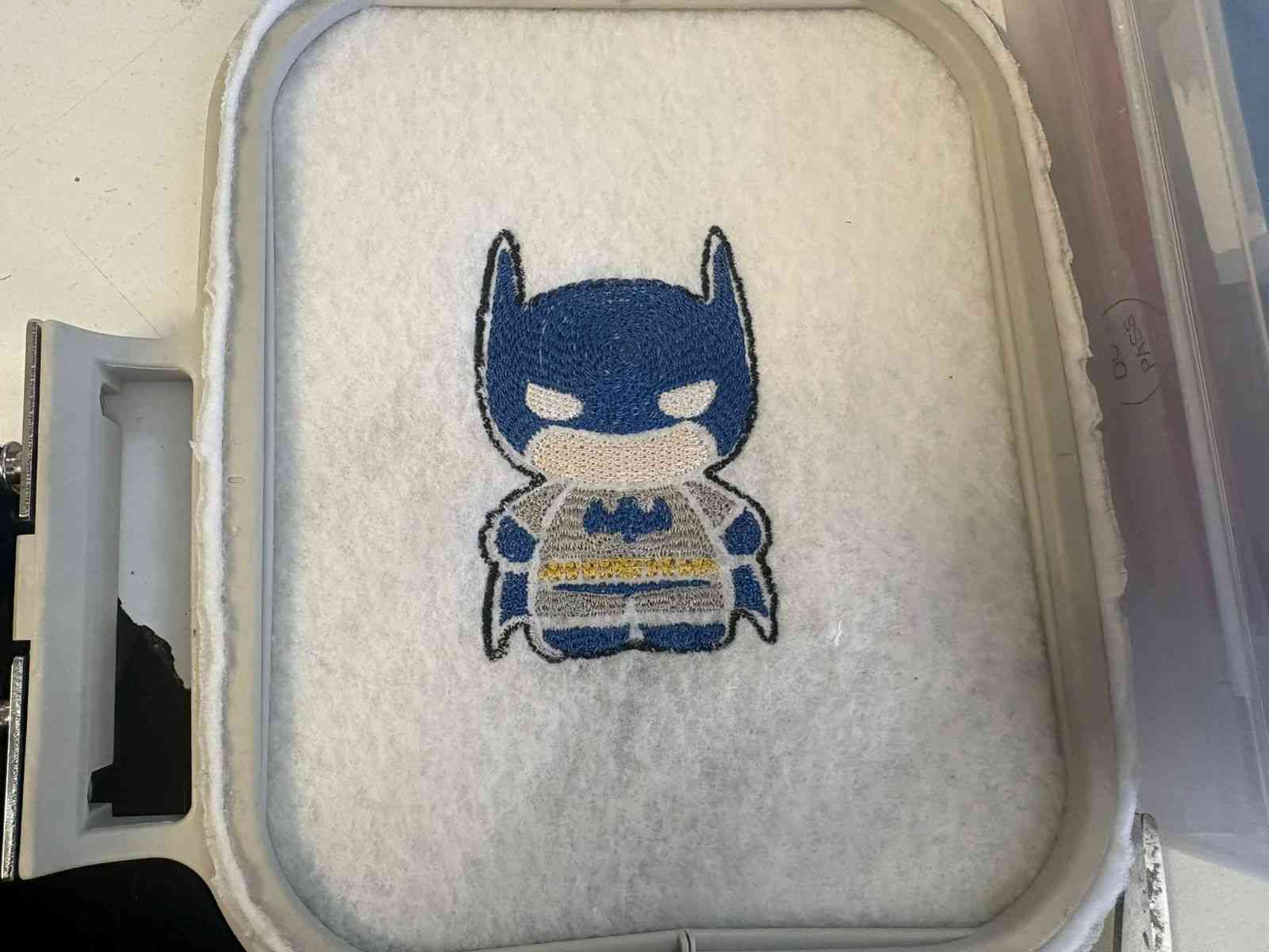
Once the machine completes all the programmed color blocks and the final trim is executed, the hoop is removed to reveal the finished piece. Here is the final embroidered result:
Problems Encountered
The only issue encountered during the process was that the automatic trim command — used to cut the thread when the machine jumps between separated sections of the design — did not execute correctly on the embroidery machine. Instead of cutting, the machine carried the thread across the fabric, leaving visible jump threads on the surface of the embroidery.
The fix was straightforward: once the machine finished the run, the jump threads were manually cut with scissors flush to the fabric. No re-stitching or design adjustment was needed, and the final result was not affected.