3D Scanning and Printing - Assignment:
3D printing is an additive manufacturing process where objects are created layer by layer from a digital model. The process begins with designing a part in CAD software, which is then converted into a printable file and processed in a slicer to generate the machine instructions (G-code). This week focused on exploring additive manufacturing and 3D scanning technologies, understanding how they enable the fabrication of complex geometries that are difficult or impossible to achieve with subtractive methods.
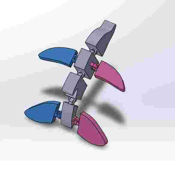
My model
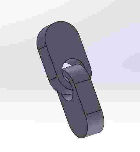
I decided to design with interlocking links, since this is not an achievable result with subtractive methods since, in CNC machines, the tools wouldn´t be able to access to make the internal gaps without damaging our structure.
Steps
I followed many methods, but many of my early designs didn´t came out correctly, I will describe the final steps when I finally got a functional dolphin.
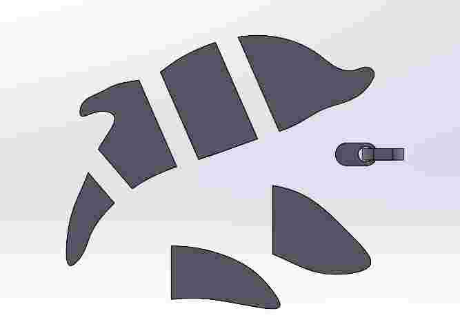
1. Reference Sketching: Import a reference image as a Sketch Picture. Use the Spline tool to trace the organic contours of the base shape, ensuring a smooth and accurate profile.
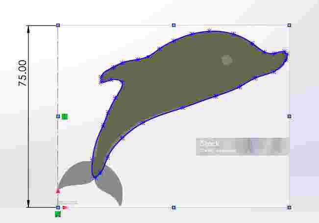
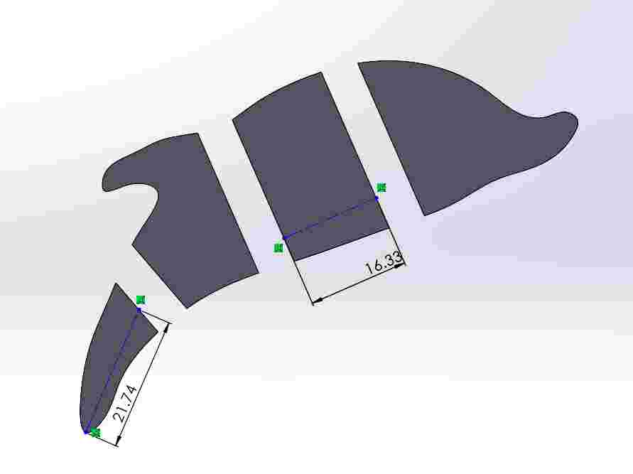
2. Main Geometry: Apply a Boss-Extrude feature to give the sketch volume. Then, use centered rectangles and the 'Extruded Cut' tool to divide the body into functional sections.
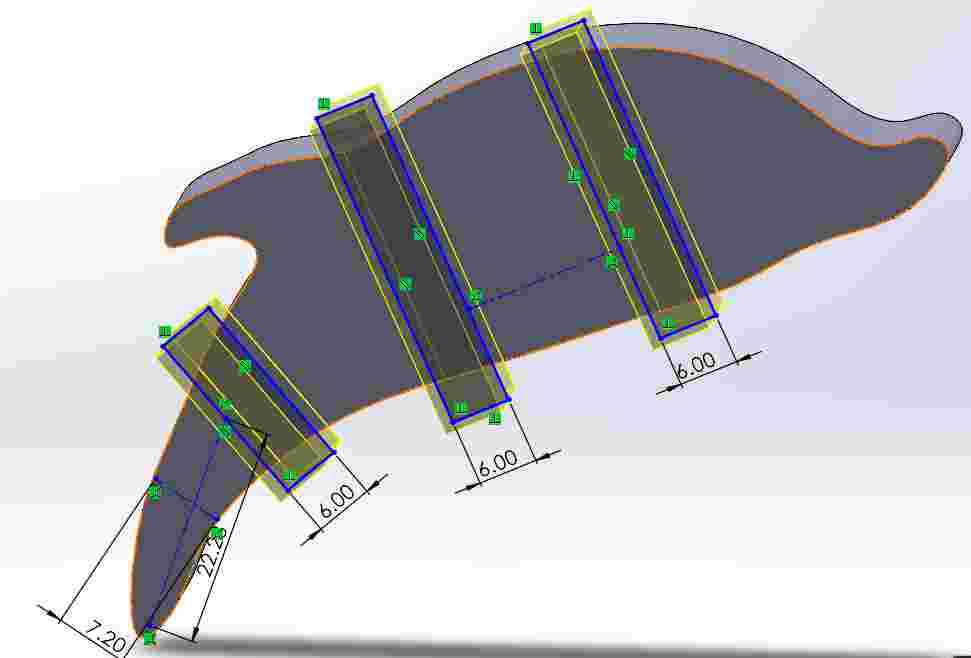
3. Layout Guidelines: Create Construction Lines (Centerlines) to define the precise spatial constraints for the rear and side fins, ensuring symmetry and alignment.
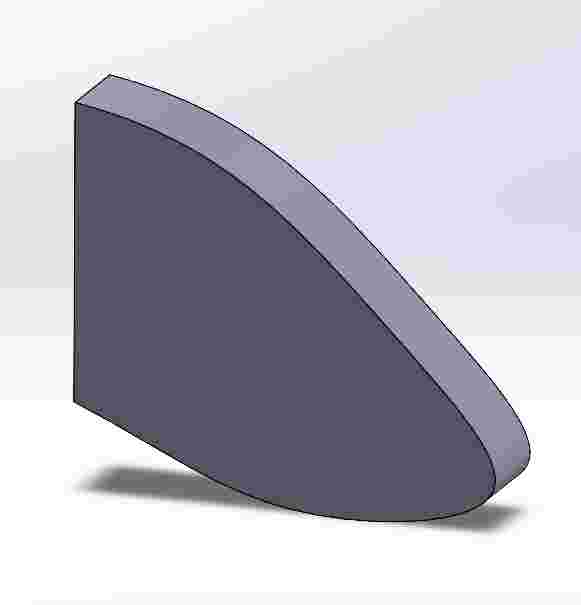
4. Side Fin Design: Sketch and extrude the side fin geometry. Use fillets on the edges to improve aerodynamics and structural strength.
5. Rear Fin Design: Model the rear fin following the established construction lines. This part is designed as an independent body for easier assembly later.
6. Joint Engineering: Design the interlocking joints (Press-fit). I applied tolerances based on material standards to account for thermal expansion and cooling during fabrication.
7. Assembly Initialization: Create a new Assembly file (.asm) and insert the main body and individual components using the 'Insert Components' manager.
8. Component Mating: Position the fins and joints on the primary side using 'Coincident' and 'Distance' mates to ensure a perfect mechanical fit.
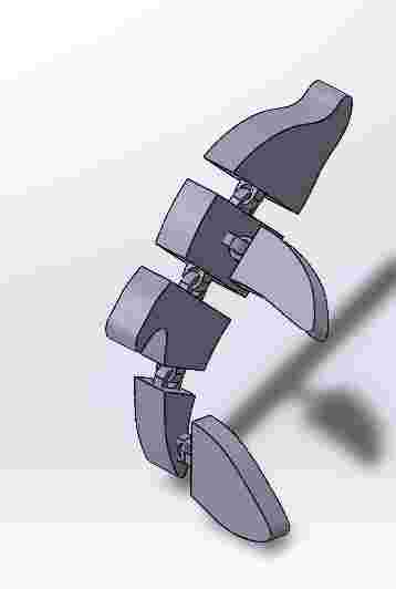
9. Symmetry Mirroring: Use the 'Mirror Components' tool across the central plane to replicate the fins on the opposite side, ensuring a perfectly balanced final design.
Software and Printing
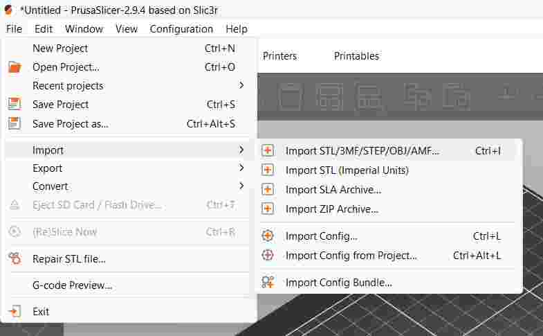
I used PrusaSlicer as the software required to make up the file for the printing.
1. Model Import: I started by importing the .STL file into PrusaSlicer to begin the preparation for 3D printing.
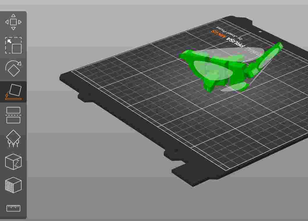
2. Orientation: Once imported, I used the 'Place on Face' tool to rotate the model, moving the support base to the dolphin's back for better stability.
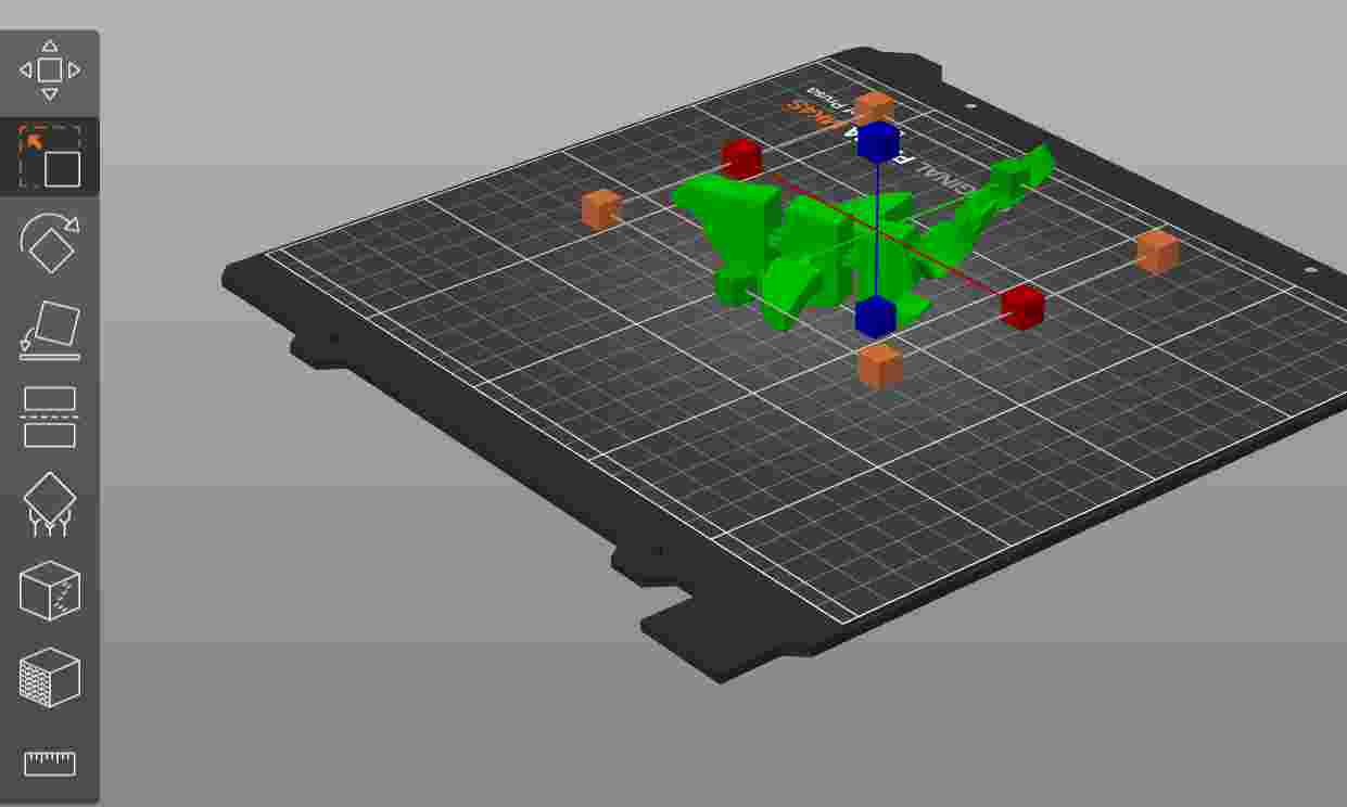
3. Scaling: I used the transformation and scaling tools to resize the dolphin to the desired dimensions for the project.
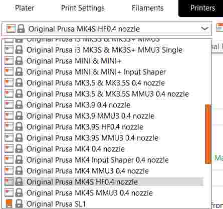
4. Printer Selection: I selected the Original Prusa MK4S profile equipped with a 0.4 mm HF (High Flow) nozzle to ensure optimal extrusion.
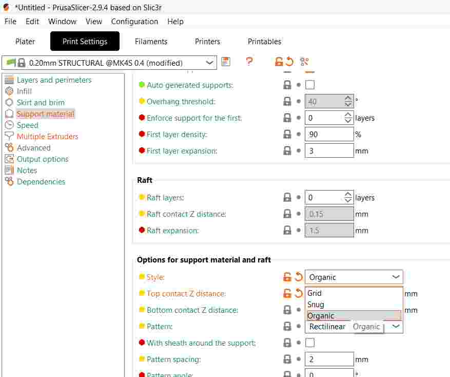
5. Support Configuration: In the Print Settings, I enabled support material and chose the Organic style. These tree-like supports are easier to remove and save material.
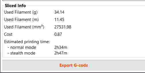
6. Slicing: I proceeded to slice the model, keeping the default parameters for layer height and speed as they were already optimized for this printer.
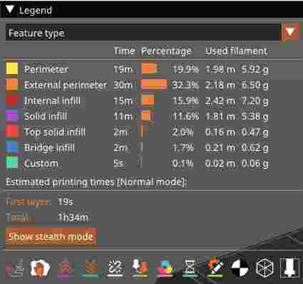
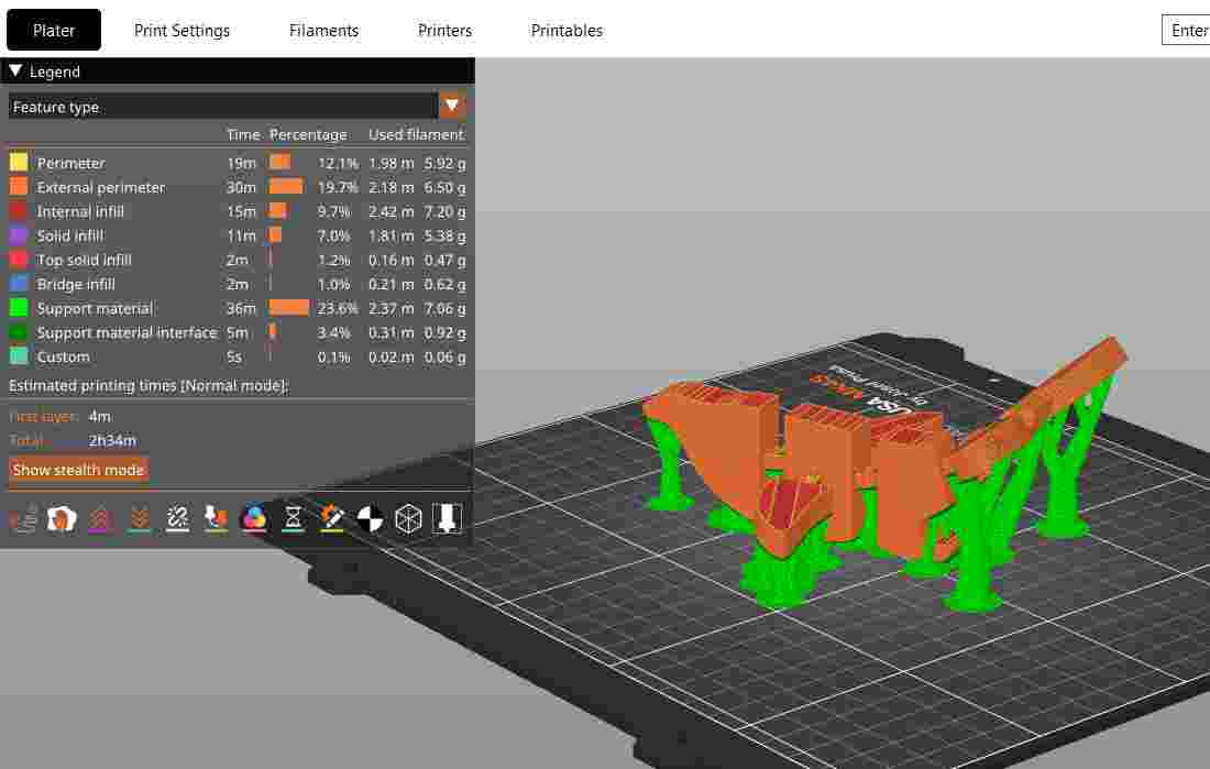
7. Slicer Preview: This view shows the generated G-code, highlighting the Organic supports that will hold the overhanging parts of the dolphin.
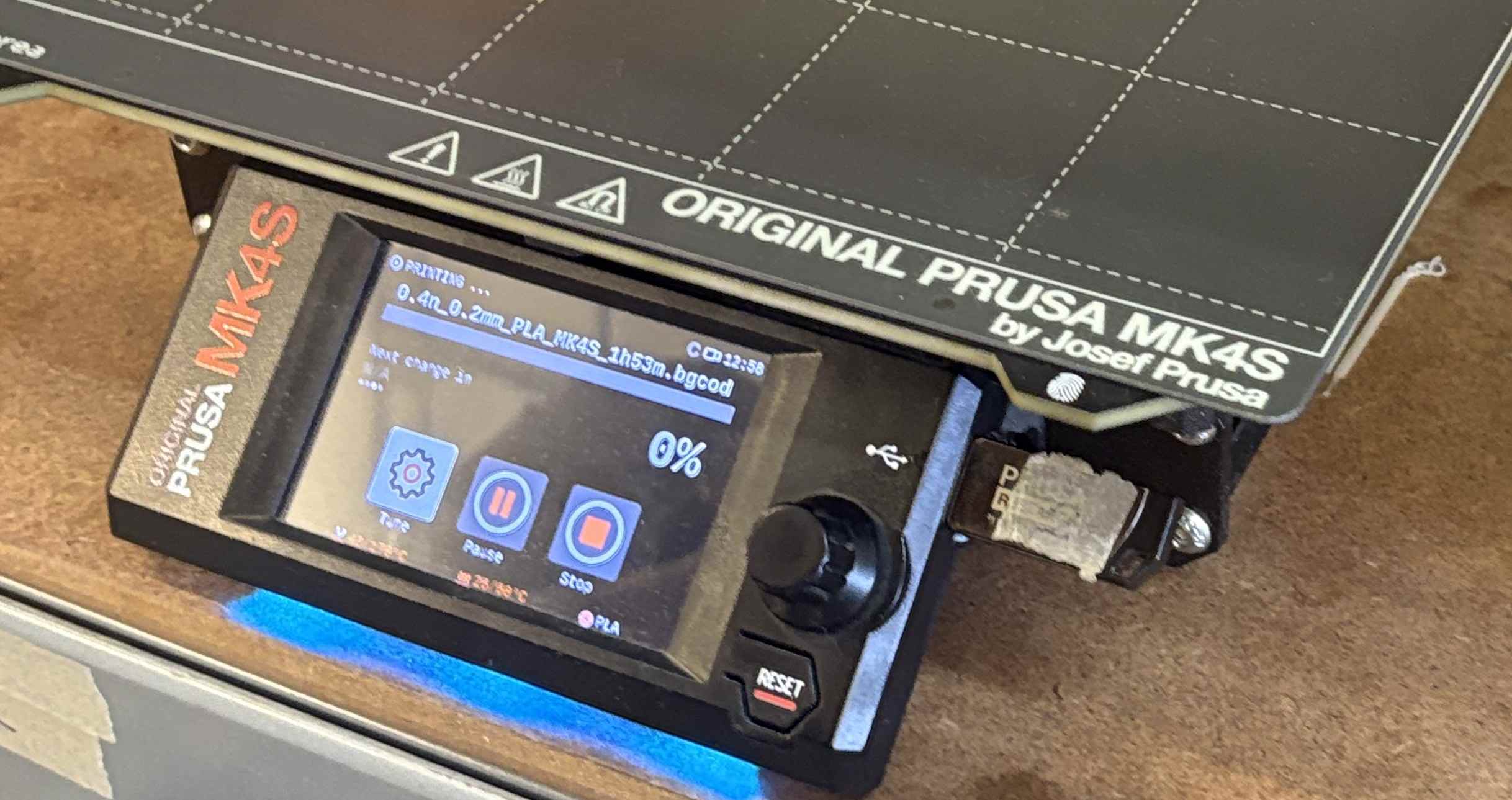
8. G-code Export: After verifying the paths, I exported the G-code file directly to a USB drive for the printer.
9. Starting the Print: I inserted the USB into the Prusa MK4S. The system automatically detects the latest file, so I simply selected 'Print'.
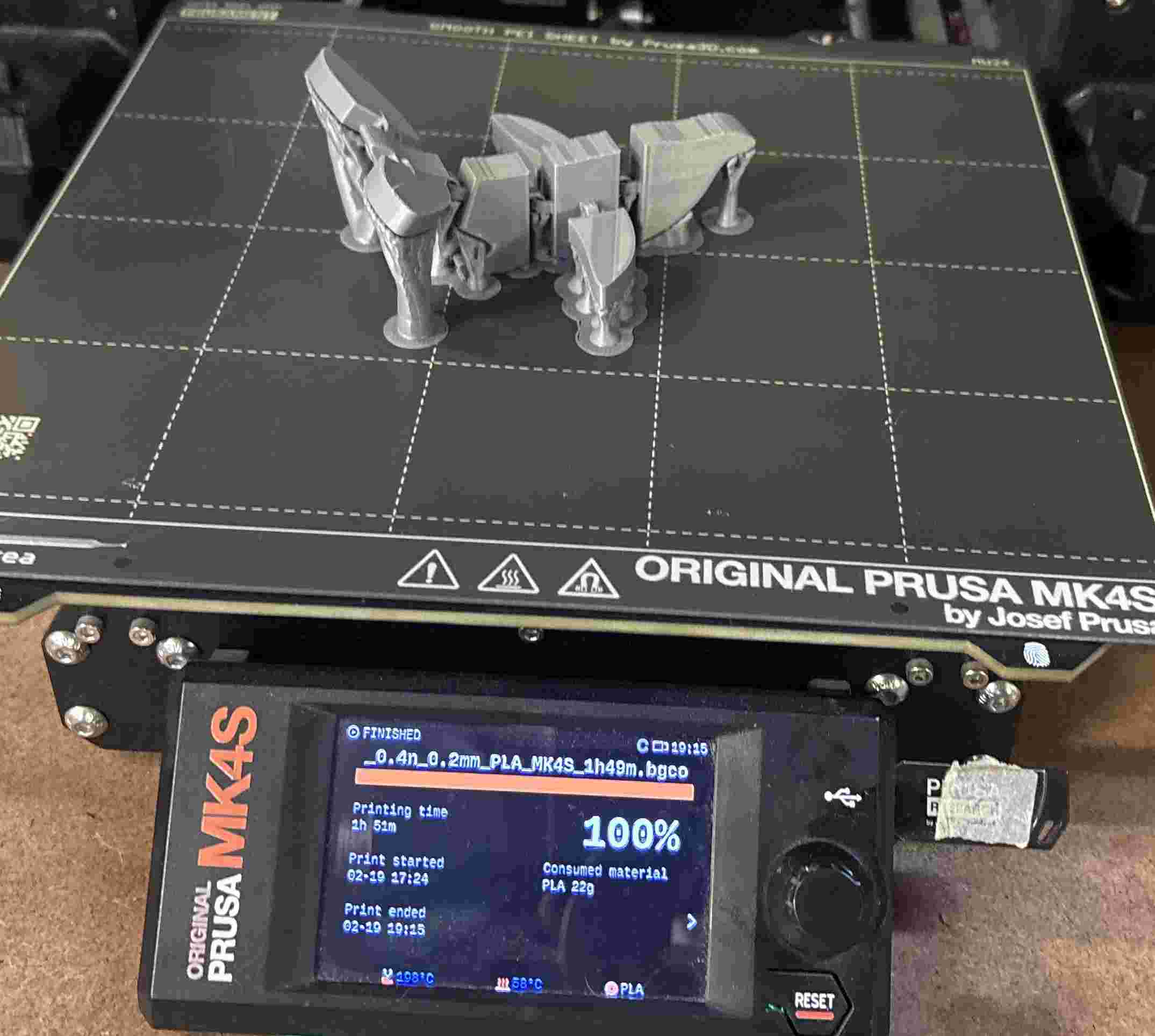
10. Printing Result: The print is finished. Here you can see the model still attached to the heatbed with the organic supports intact.
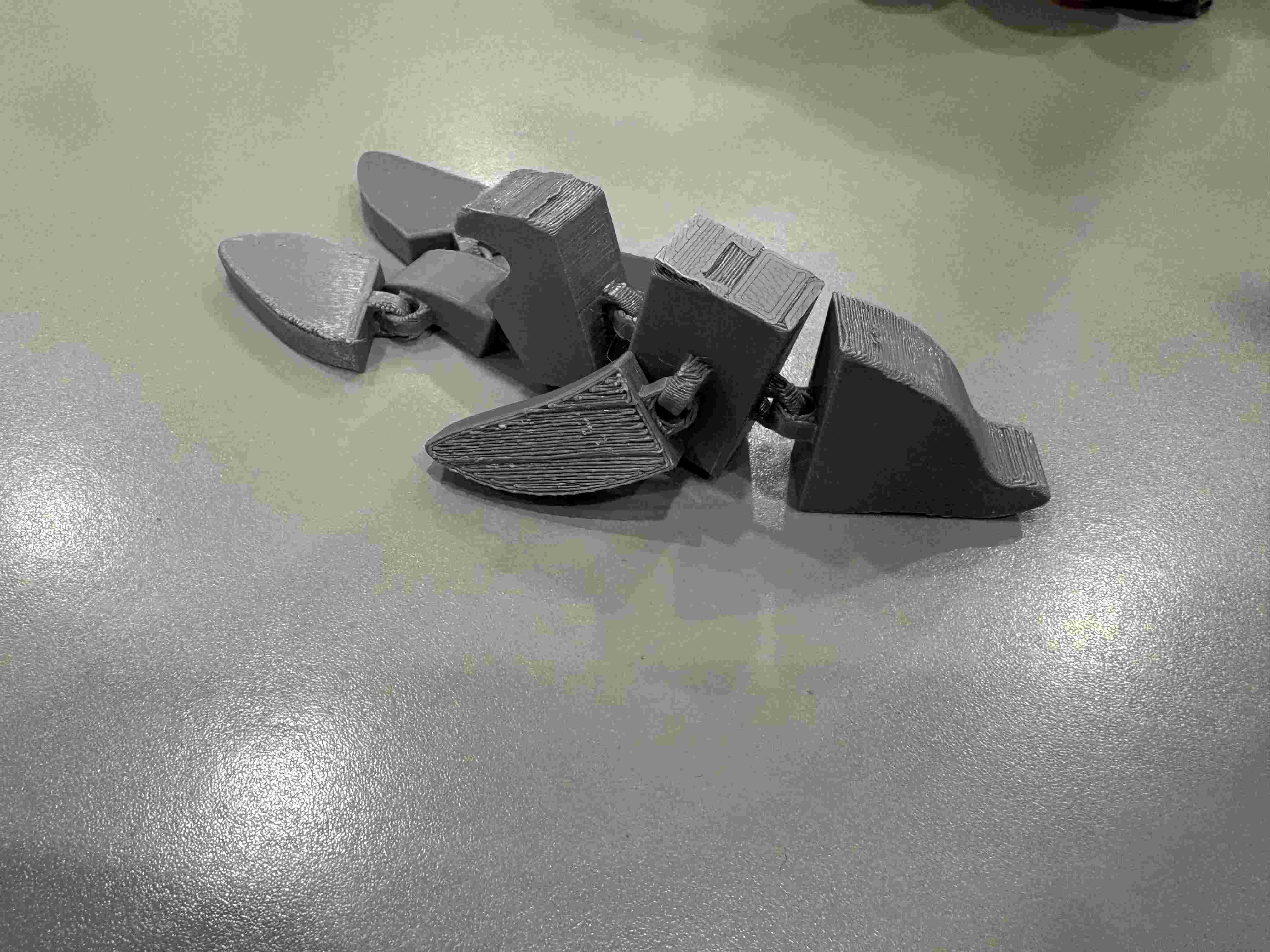
11. Post-Processing: Final result after carefully removing the supports. The surface finish is clean, and the organic structures left minimal scarring.
Slicing Configuration & Pre-set Parameters
For this project, as I previously said I utilized the optimized factory profiles for the Original Prusa MK4S. Since these profiles are extensively tested for the 0.4 mm HF nozzle, I decided to keep the core parameters as pre-established to ensure maximum reliability and print quality.
| Technical Parameter | Value / Preset | Technical Justification |
|---|---|---|
| Layer Height | 0.20 mm (Quality) | Standard resolution that balances printing speed with smooth surface detail for organic shapes. |
| Infill Density & Pattern | 15% / Grid | Provides a sturdy internal framework for the model while keeping filament consumption efficient. |
| Perimeters (Walls) | 2 Vertical Shells | Ensures the external surface is solid enough to hide the internal infill pattern. |
| Top/Bottom Layers | 4 Top / 3 Bottom | Guarantees a fully closed and smooth top surface, preventing any holes in the final geometry. |
| Printing Temp (PLA) | 210°C / 60°C | Optimized thermal settings for the 0.4mm HF nozzle to maintain consistent plastic flow. |
| Cooling Fan Speed | 100% | Maximum cooling after the first layer is critical for PLA to prevent sagging on overhanging parts. |
| Support Style | Organic (Modified) | The only custom change; used for its tree-like structure that is easy to remove from complex curves. |
| Top Contact Z Distance | 0.20 mm | Pre-set 'Air Gap' that allows the organic supports to detach cleanly without scarring the model. |
Technical Note: Using the "Organic" support setting was crucial for the dolphin model due to its complex overhangs. Unlike "Snug" supports, organic branches reach only the necessary points, leaving fewer scars on the final 3D printed surface.
3D Scanning
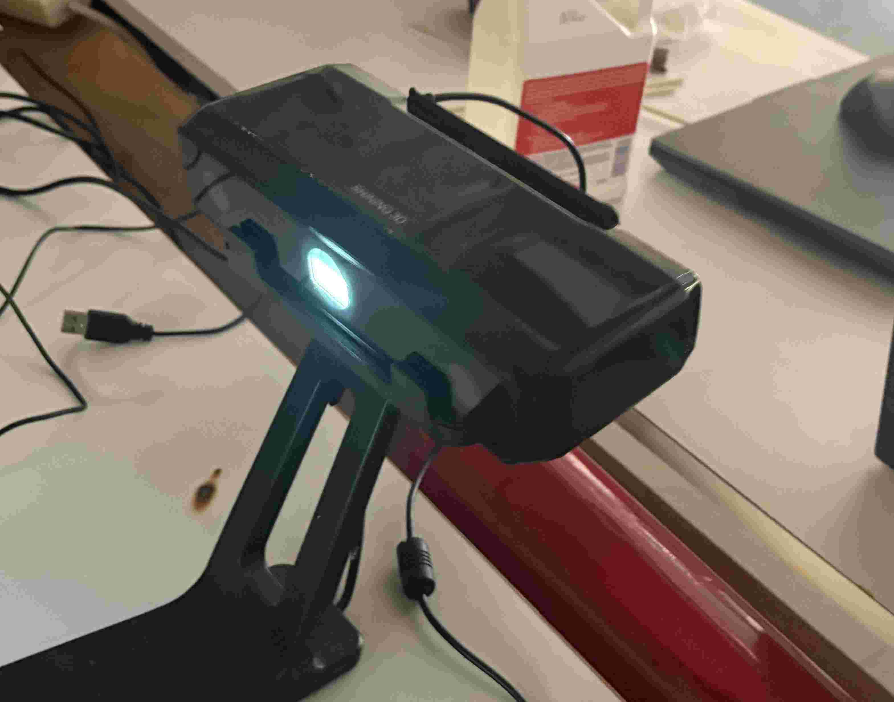
I used EinScan-SE scanner
1. Hardware Setup: I started by setting up the 3D scanner. Proper positioning and lighting are essential before initializing the software interface.
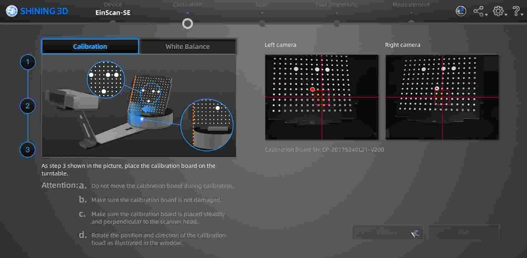
2. Calibration: Upon launching the software, I performed a full calibration to ensure the sensors accurately map the spatial coordinates of the object.
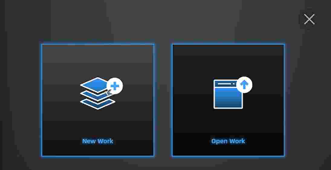
3. New Project: I initialized a 'New Work' session to define the project parameters and workspace environment.
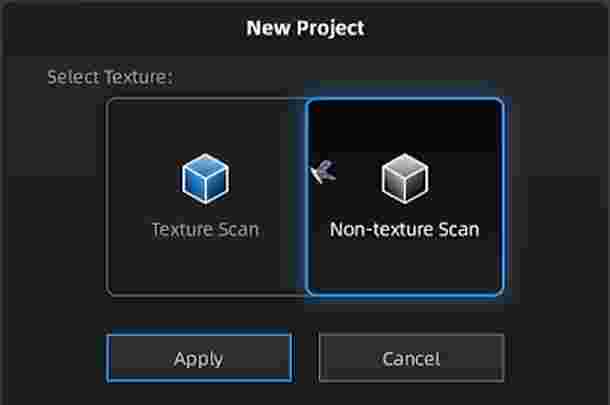
4. Scan Mode Selection: I chose the Non-Texture Scan option, as I only needed the geometric data (mesh) without capturing the surface color information.
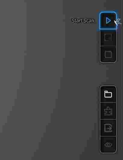
5. Active Scanning: I pressed 'Play' to begin the capture. The scanner uses structured light to triangulate the surface points of the object in real-time.
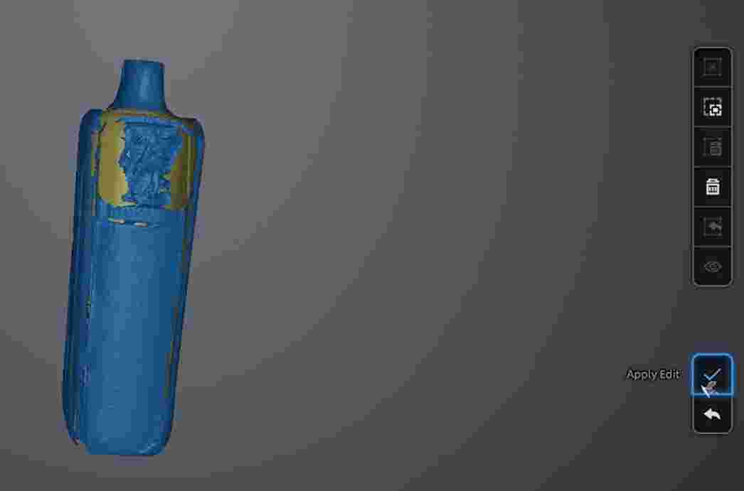
6. Edit Application: After each pass, it is necessary to apply the edits. This cleans the temporary data and prepares the point cloud for the next angle.
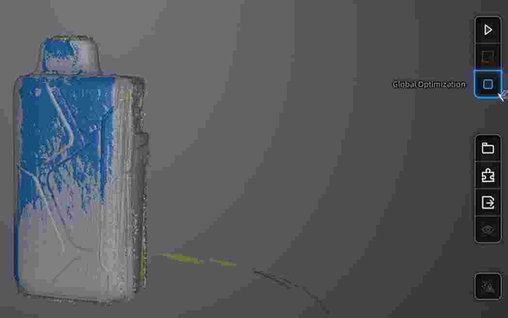
7. Mesh Optimization: I used the optimization tool to align the different scan passes and improve the overall density and quality of the point cloud.
8. Data Finalization & Printing: Once the scan was complete, I saved the file as an .STL. I then followed the 3D printing workflow (Slicing and G-code generation) to manufacture the physical replica.
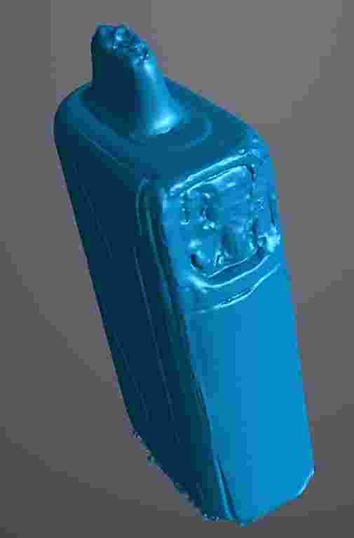
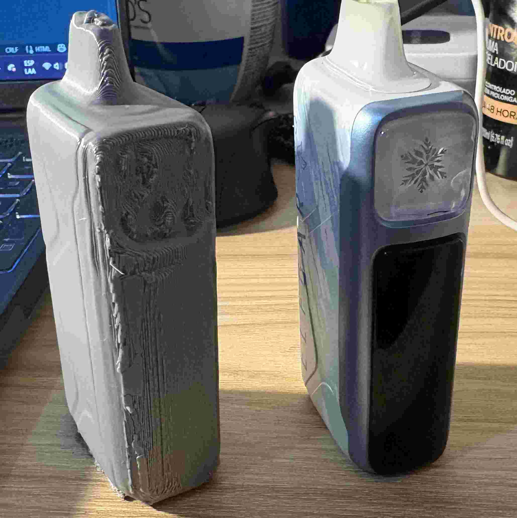
9. Final Result & Material Analysis: The final print shows some imperfections. This is common when scanning reflective or dark materials, which can interfere with the scanner's light patterns.
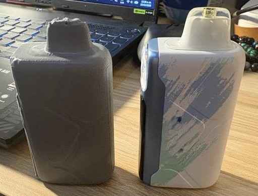
10. Surface Quality: Close-up view of the printed model. The surface noise is a direct result of the original object's material properties during the capture phase.
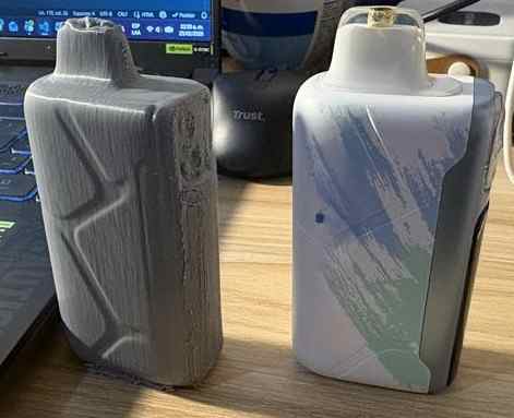
11. Technical Conclusion: Despite the minor artifacts, the overall geometry was successfully captured. For future scans, using a matting spray could help reduce these imperfections.
This week provided a comprehensive overview of the digital-to-physical workflow, from 3D scanning to final print. While the EinScan-SE successfully captured the overall geometry of the object, the process also revealed the challenges of scanning certain material properties, such as reflectivity. This experience was invaluable for understanding how to optimize mesh data and adjust printing parameters—like layer height and infill—to produce accurate replicas. Overall, these skills are essential for reverse engineering and rapid prototyping in future projects.
Files
└── Week5Printing
    ├── Aleta Frontal.SLDPRT
    ├── Aleta Trasera.SLDPRT
    ├── Cadena.SLDPRT
    ├── Cuerpo.SLDPRT
    ├── Delfin.3mf
    ├── Delfin.SLDASM
    ├── Delfin.STL
    └── Vapin.stl