Computer Controlled Machining
During the group characterization, we learned to master the CNC workflow, from bed alignment to the importance of fixing the material. We performed speed and feed tests to optimize plywood cutting, validating that a correct configuration prevents burning the wood or damaging the tool.
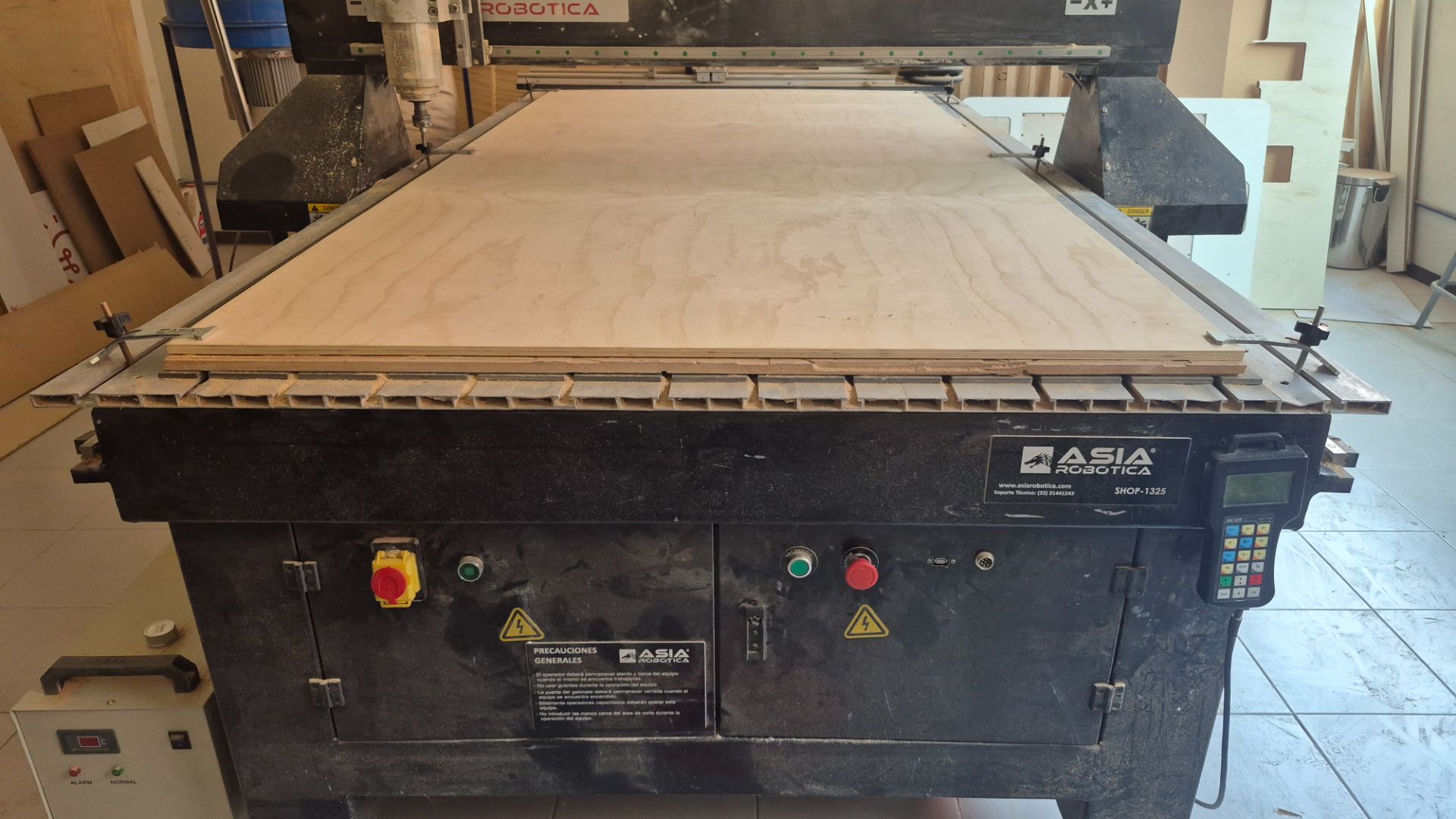
Regarding safety, we operated the Asia Robótica SHOP-1325 router following strict protocols: mandatory use of safety glasses, hearing protection, a lab coat or overalls, and safety shoes. It is essential to keep the area clear, never wear gloves near the rotating spindle, and always be alert near the NK105 controller and the emergency stop button.
Group Assignment Week 7
After working with the precision of laser cutting, the challenge was to design and manufacture something large using a CNC milling machine. The focus was not only on the machine itself, but also on understanding the material's behavior during cutting.
Design Process
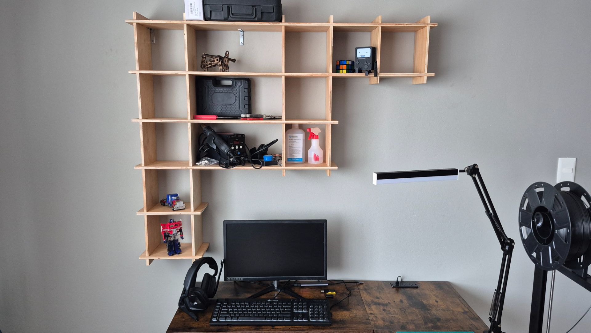
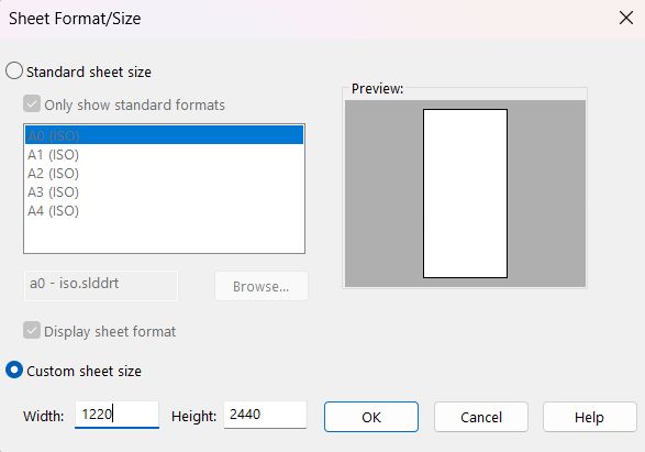
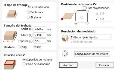
This week, I decided to design a floating shelf to install above my desk. The goal is to optimize my workspace by keeping essential tools and items within easy reach. My design is inspired by a piece of furniture my father built years ago, which used a system of grooved wooden boards and cross joints to create modular compartments. We were provided with a full-size 1.22m x 2.44m x 12mm plywood sheet. I took this into account for the design.
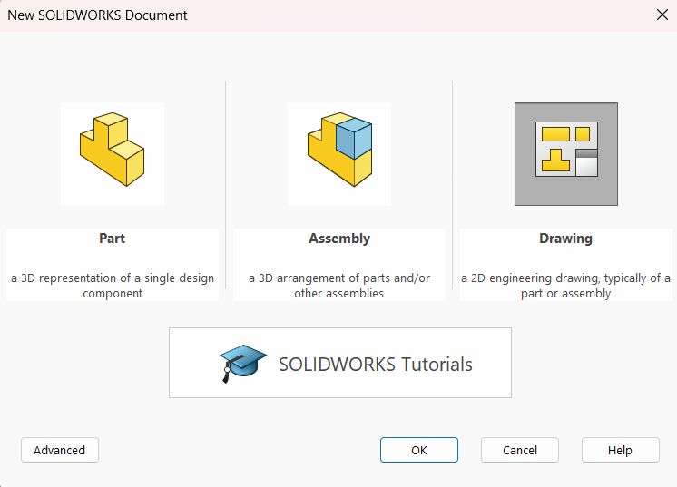
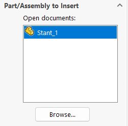
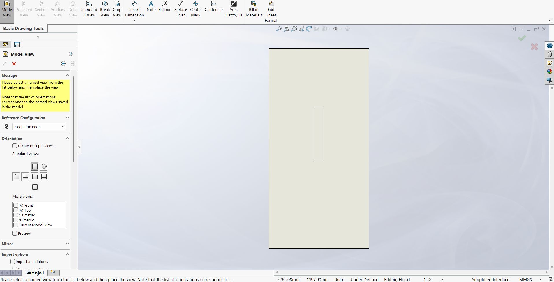
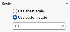
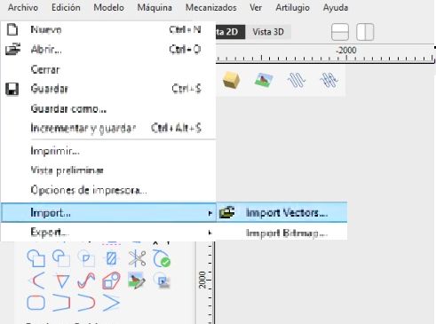
For the design, I used SolidWorks as CAD software, generating the furniture assembly to ensure the pieces fit together and preview my idea before manufacturing it. I then exported the files as .dxf to send to pre-production in VCarve to obtain the file that the router reads.
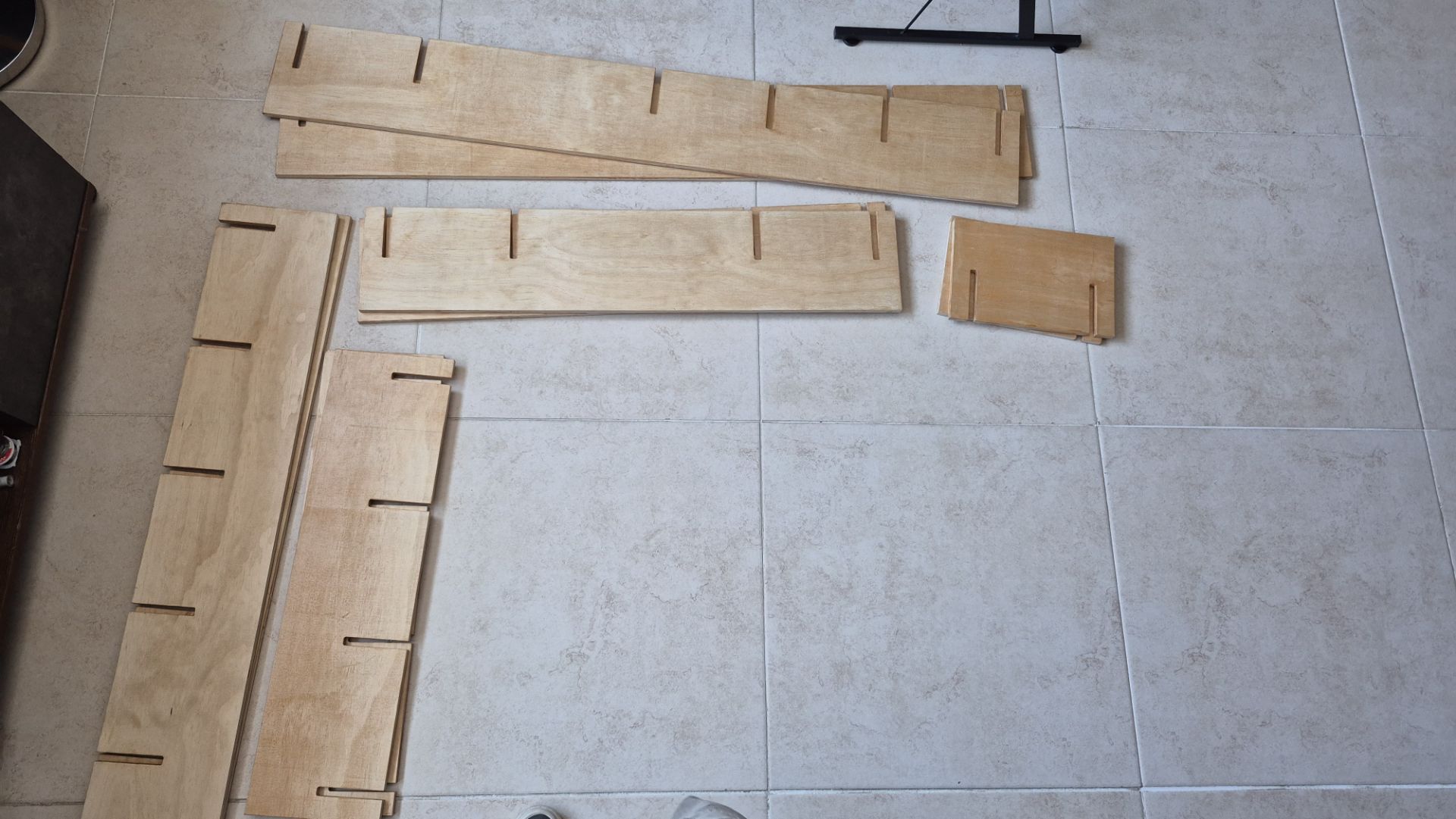
 Shelf Parts
 Shelf Assembly
Shelf Parts
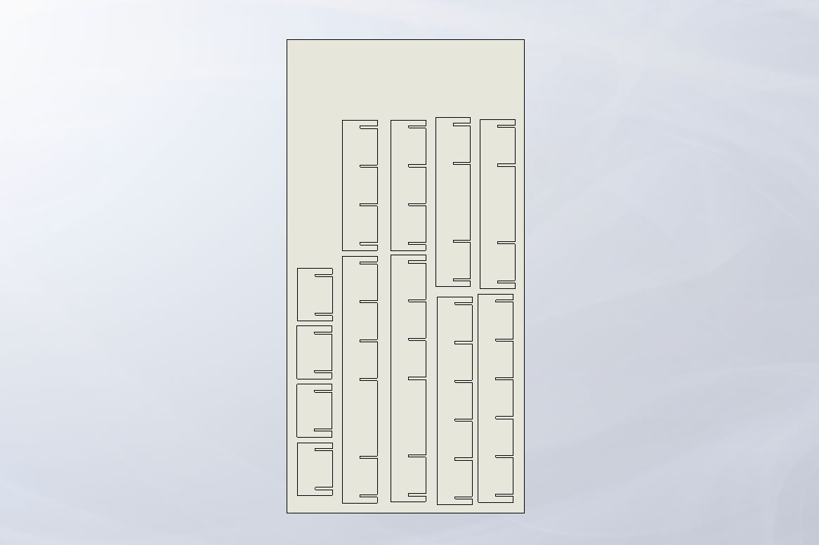
I designed a parametric base plate with a series of slots spaced every 20 cm, each 1.2 cm wide to accommodate the material thickness. To make the design adaptable, I developed the entire piece using Equations. By linking the total plate length and spacing to a set of global variables, I can automatically scale the entire piece simply by modifying the number of slots. This ensures that the structural integrity and symmetry of the shelving unit remain constant regardless of the dimensions. I didn't use tolerances on the joints because, being a piece of furniture, I require strong joints, even though this means it's more difficult to assemble.
This piece was the basis for the others, as I already said, by using the Equations and Global Variables I was able to obtain the other pieces just by changing the number of joints.
Shelf Assembly
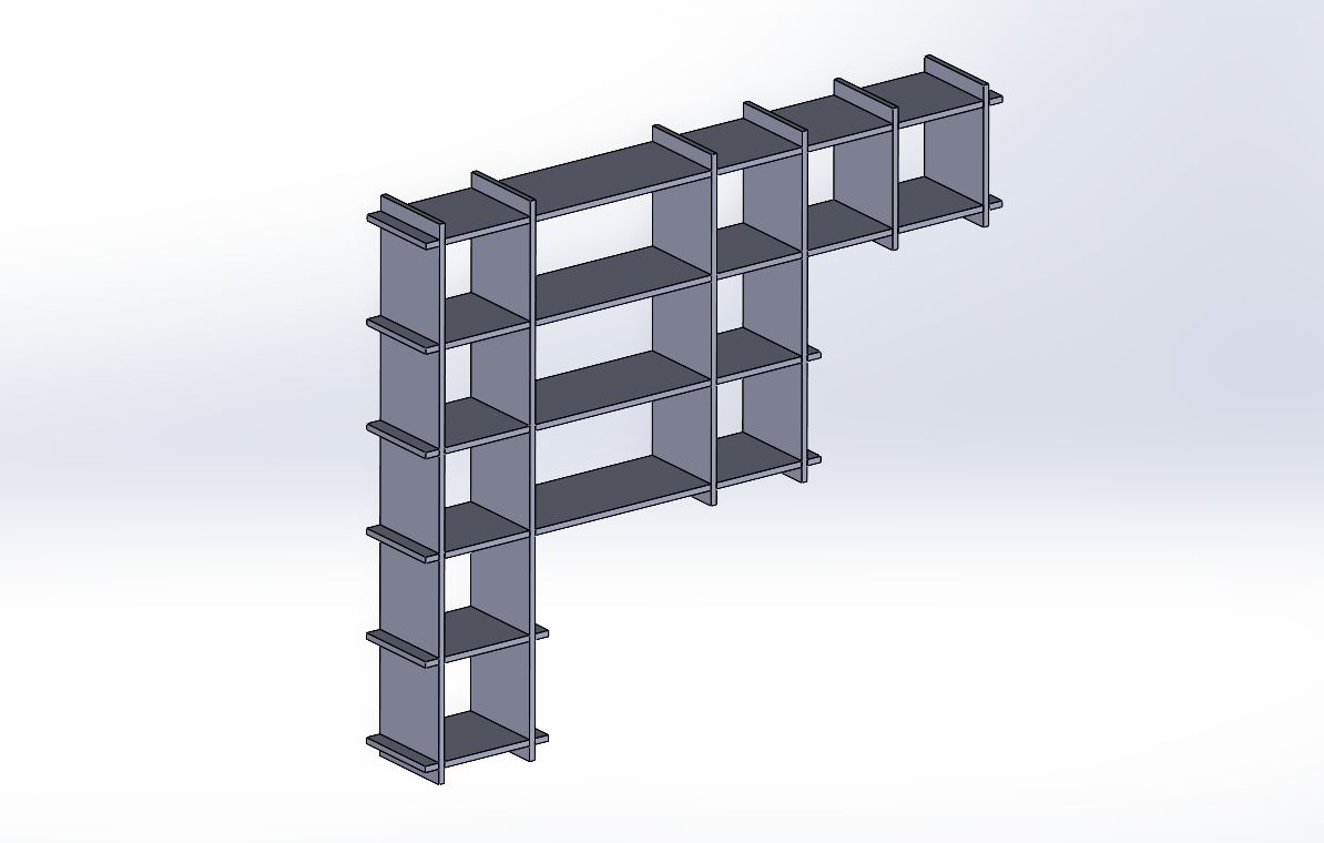
I created a 3D assembly in SolidWorks to validate the design and check for any interference at the joint. This virtual preview was vital to ensure the joint system would function correctly. It also gave me the flexibility to edit and refine individual parts, so that once the CNC machine started cutting, each piece would fit together exactly as planned.
After generating the assembly, I made several modifications to the parts. The final design presented here is the result of that process.
Exporting to DXF
Download Shelf Files
Pre-machining
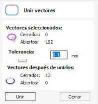
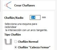
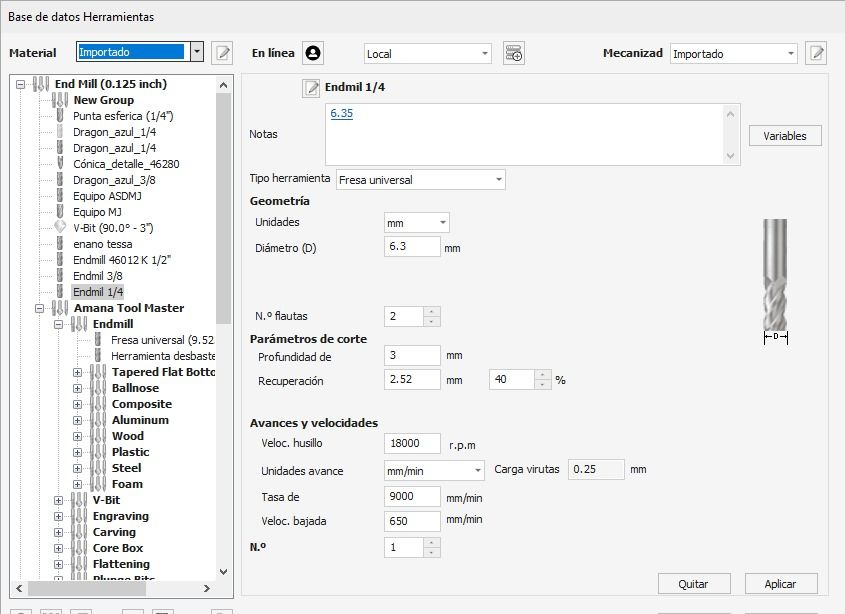
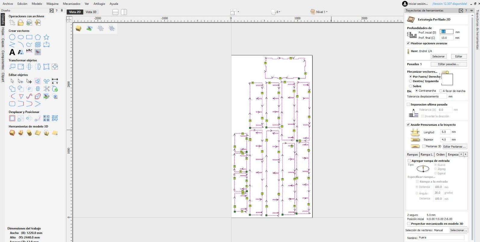
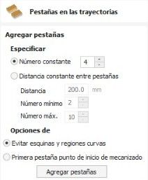
I processed the design in VCarve v12 to prepare it for machining. This preparation involved adding dogbone joints to the interlocking joints to facilitate mechanical assembly and inserting tabs to prevent the parts from moving or lifting during cutting. I also defined the cutting parameters according to the material properties and the milling cutter specifications.
Final Preview
The simulation in VCarve's 3D View served as a validation before physical fabrication. At this stage, the software renders the material, allowing me to visually confirm that the Profiling and Pocketing strategies will execute as planned.
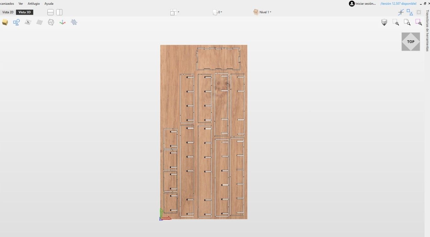
By inspecting the virtual model, I was able to verify the presence and exact location of the clamping tabs, confirming that they are robust enough to hold the parts securely to the material sheet without compromising the integrity of the cut.
Machining
With the design and pre-machining steps completed, I proceeded to the physical fabrication of the shelf. I set up the CNC router, ensuring that the material was securely clamped to the bed and that the tool was properly installed and calibrated.
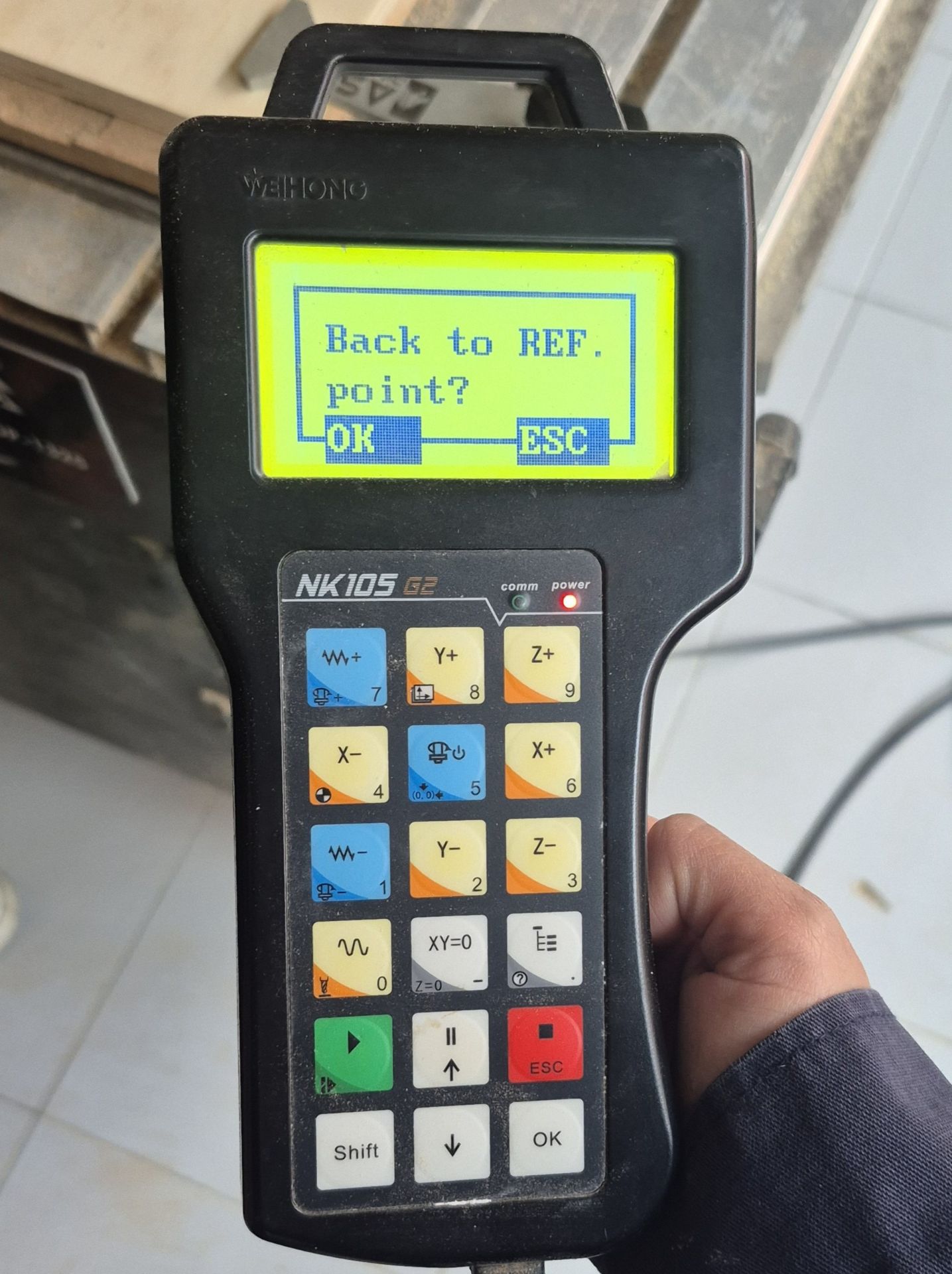
NK105 DSP Controller
- X, Y, and Z Axes:
- X-, X+ / Y-, Y+: Control the longitudinal and transverse movement of the spindle. They are used to manually position the milling cutter on the material.
- Z+, Z-: Control the spindle height. They are critical for establishing the starting point of the cut and avoiding collisions with the bed.
- Calibration and Zero:
- XY=0: Sets the origin of coordinates on the horizontal plane (local home). This is the point where the VCarve design will begin cutting.
- Z=0 Shift + XY=0: Defines the surface of the material or the bed as the zero height point.
- Spindle Control:
- On/Off button with milling cutter icon: Allows you to manually turn the spindle on or off to verify that the tool is rotating correctly before starting the program.
- Execution and Stop:
- Green Play/Run button: Starts the selected G-code file.
- Red ESC/Stop Button: Stops the machine immediately in case of emergency or error.
- Pause Button: Temporarily stops the cut, allowing you to check chip removal or the cutter's condition without losing the file's progress.
- Speed and Modes:
- W~ / W+ Wave Buttons: Adjust the Feed Rate Override (feed rate override) in real time while the machine is cutting.
- Shift: Used in combination with other buttons to access secondary functions, such as returning to the reference point.
It is extremely important to place the zeros on the X, Y, and Z axes respecting the configuration established in VCarve, with the origin in the lower left corner and the tool touching the material, so that the router has the path and does it correctly.
To achieve this, I used the X-/X+ and Y-/Y+ controls to move the spindle to the lower-left corner. Then, using the Z+/Z- controls to adjust the height, I lowered the tool until it touched the material surface. Finally, I set the origin by using the XY=0 and Z=0 (Shift + XY=0) commands.
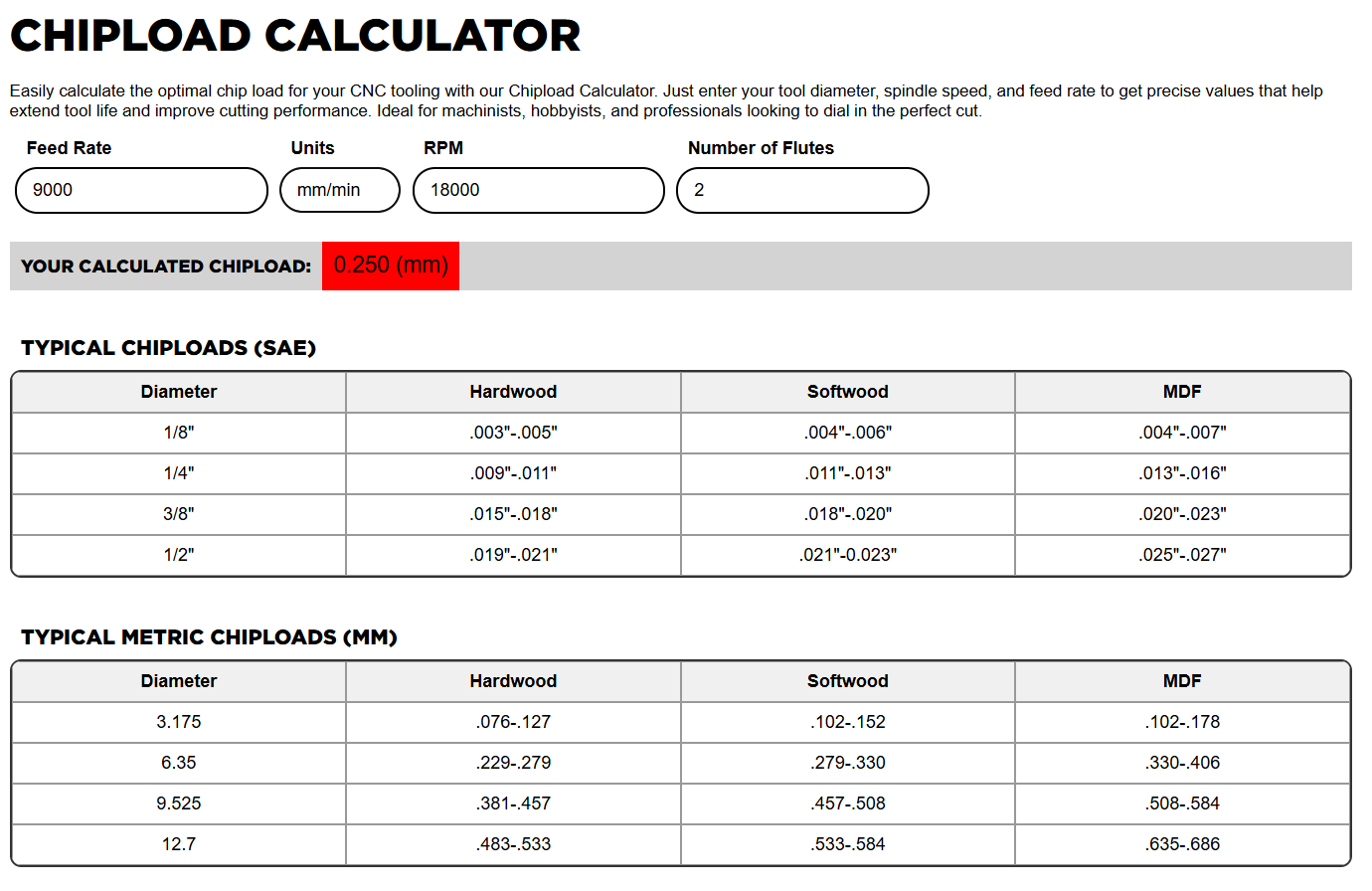
Before cutting my pieces, I cut a test piece to see how the material behaved at the speed I calculated.
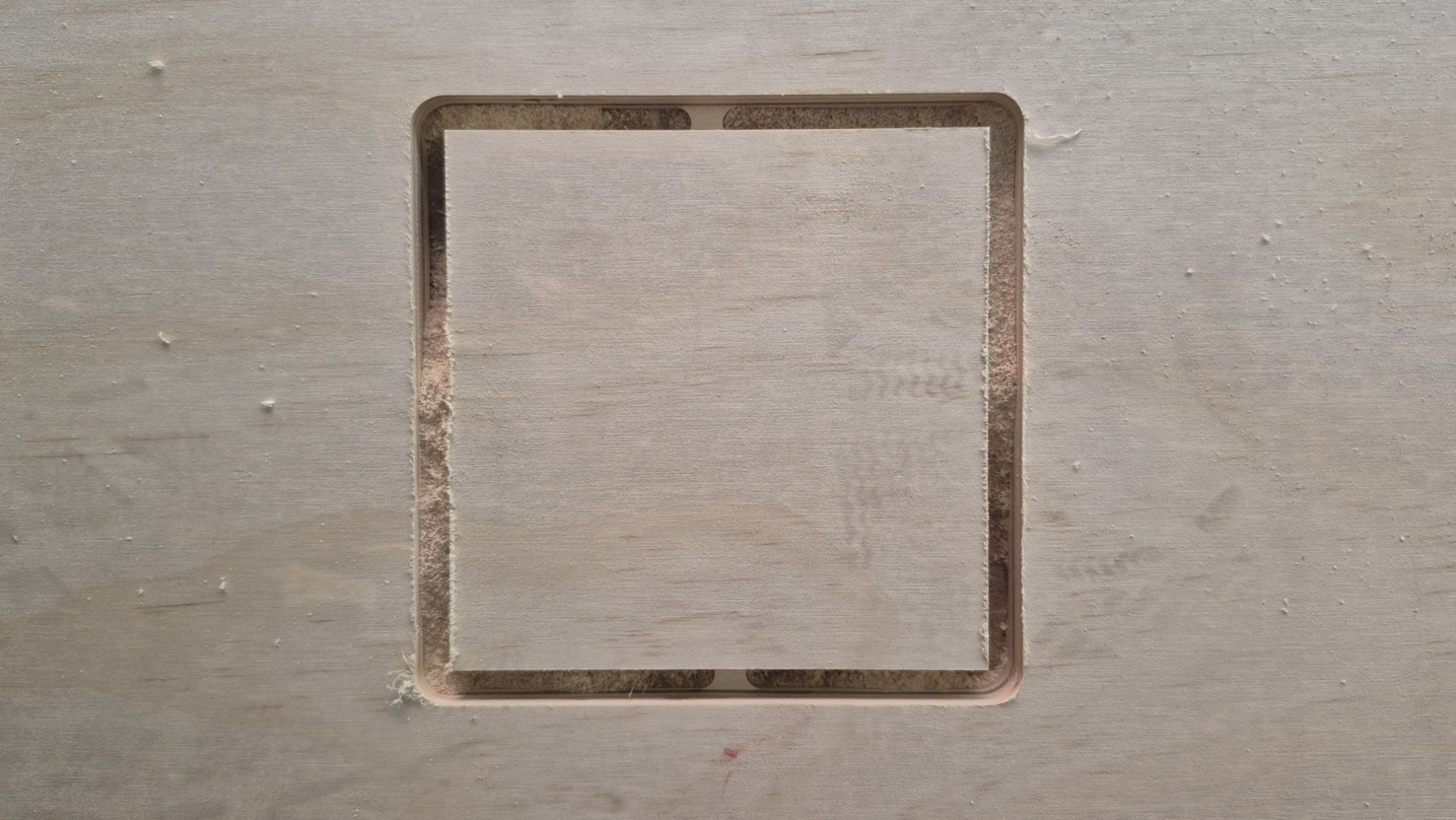
Thanks to this test I realized that the feed speed was too high. This was because one of the clamping tabs fractured and weakened, risking the material coming loose and causing an accident. So, with the help of the controller, I reduced it to 40%.
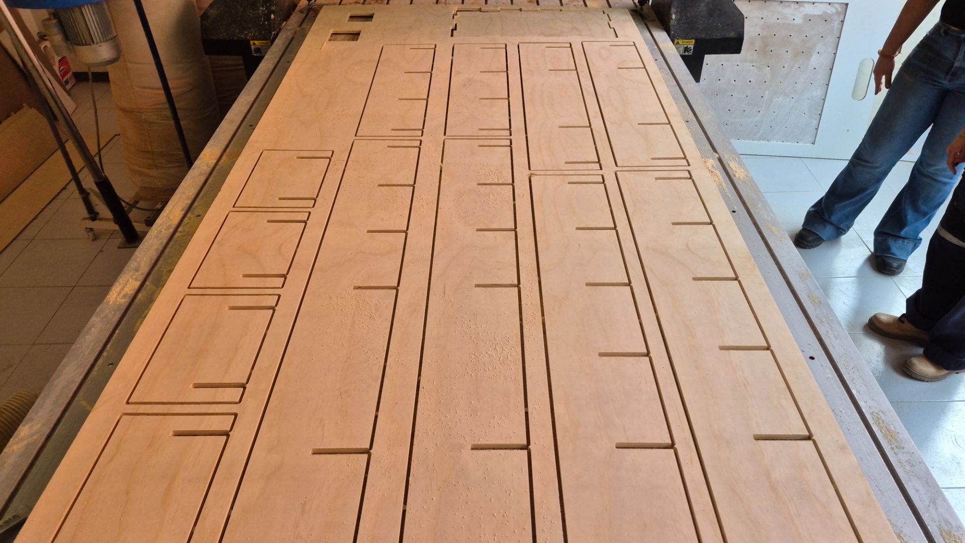
With the source correctly defined and the Feed Rate changed, I was ready to cut my shelf.
During the cutting process I kept a close eye on the router in case anything went wrong, with my finger ready on the Stop button, and I was also vacuuming up the resulting shavings to prevent them from overheating.
Post-Machining
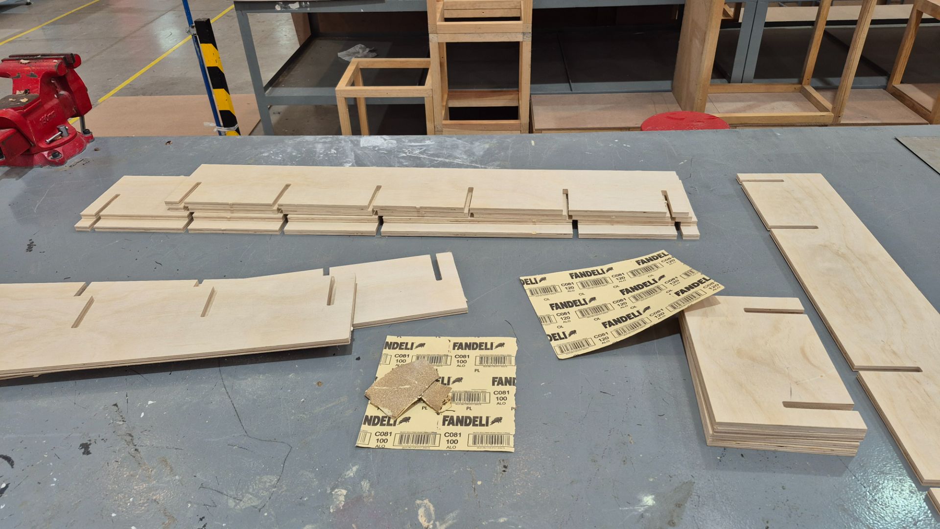
After machining the pieces, I cut the tabs with a hacksaw so as not to risk breaking parts of the wood.
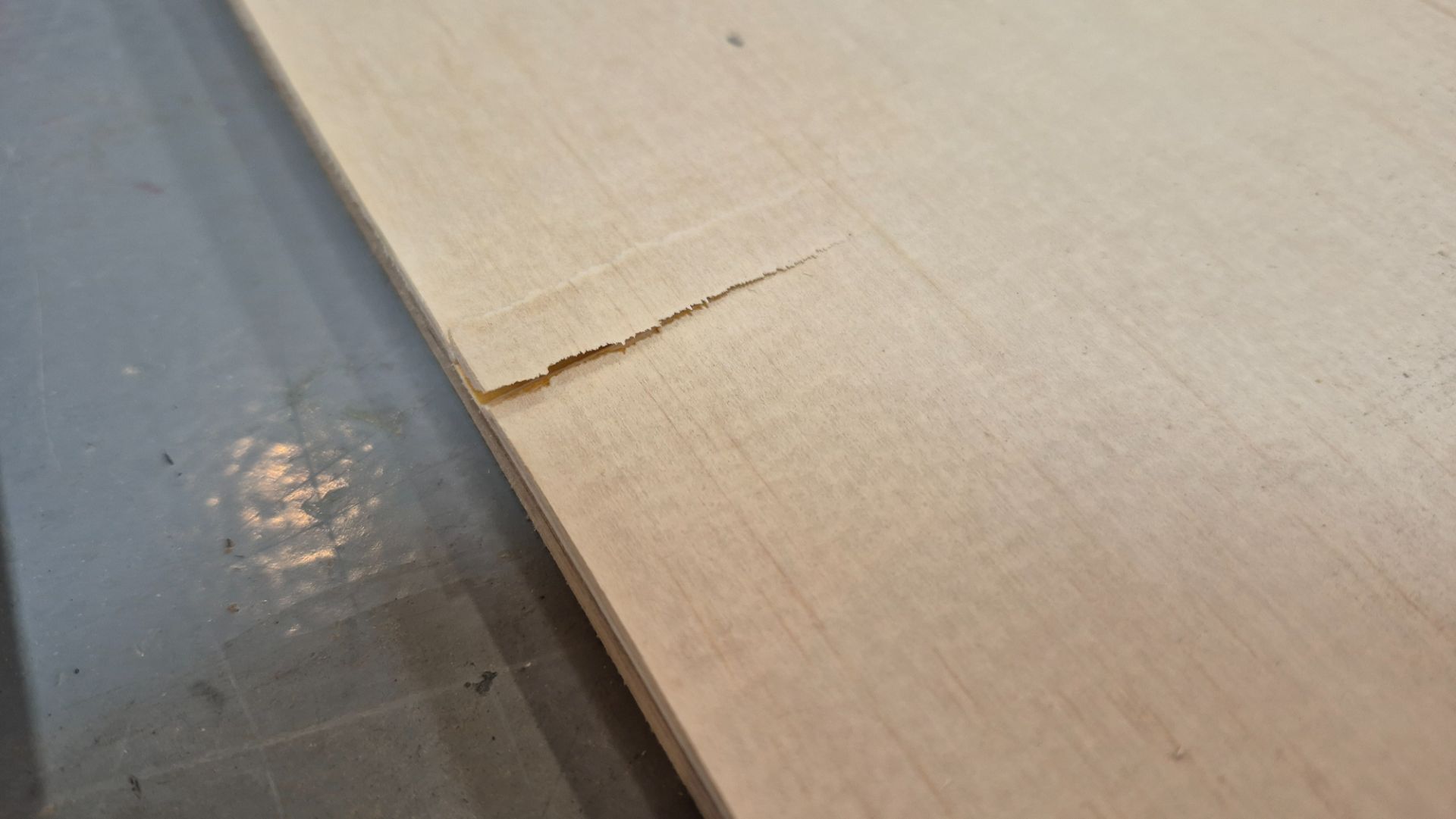
When separating a piece from the plywood sheet, a small section of the top layer chipped and began to lift. To fix this and prevent the chip from spreading, I applied white wood glue to the affected area and held it in place until it dried. Once the glue had fully cured, I sanded the surface to remove any remaining roughness and ensure a smooth, even finish.
After cutting the tabs, I sanded the edges of the boards to remove the excess with 100 grit sandpaper, and sanded the entire surface to prepare it for varnish with 220 grit sandpaper.
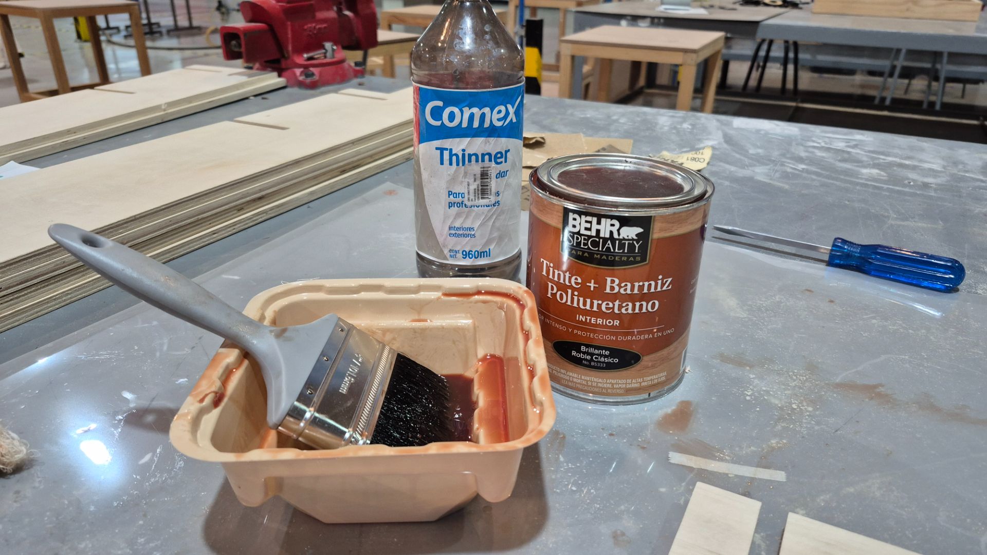
To finish the post-machining, I applied Behr Specialty Classic Oak-tinted polyurethane varnish. I used a brush to apply the varnish and thinner to clean the area.
Assembly and Placement
After the varnish dried, I assembled the shelf by interlocking the pieces. The joints fit together perfectly, and the structure is very sturdy without the need for glue or screws.
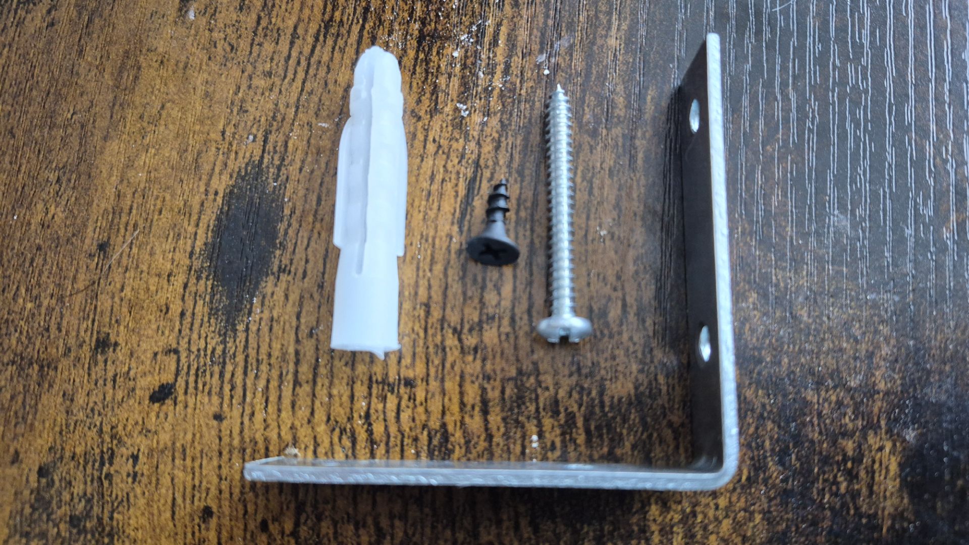
Finally, I installed the shelf on the wall above my desk using L-shaped brackets and screws to ensure it is securely anchored.
Final Result