Computer Controlled Cutting
This week I put 2D design into practice. I designed modular parts in SolidWorks using parametric equations to make them easier to modify. I designed these parts with vehicle assembly in mind. I also cut the Autobots logo out of vinyl to decorate my home soldering station. I used Inkscape to vectorize the image since the machine requires a vectorized image in .svg format.
Laser Cutting
Group assignment
The following link contains the group activity where safety standards, laser cutter characteristics, and parameters were documented. Different types of joiners were also cut, the kerf was checked, and the software used to modify documents to be cut was described.
Group Assignment Week 3
In this group exercise, I learned about the responsible and technical use of the laser cutter. I learned that safety comes first, from ensuring the fume extraction system is on to never leaving the machine unattended to prevent fires.
On the technical side, we explored material characterization to understand the kerf and how it affects the fit of the pieces. We also experimented with different power, speed, and frequency parameters, observing how they vary depending on whether the objective is to engrave or cut wood. Finally, we analyzed various types of joints, such as comb and groove joints, to achieve solid mechanical assemblies without the need for glue.
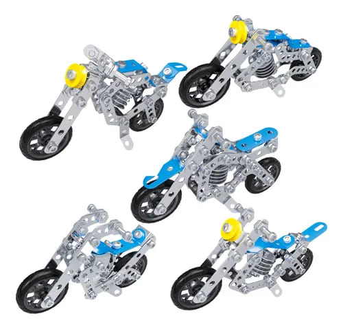
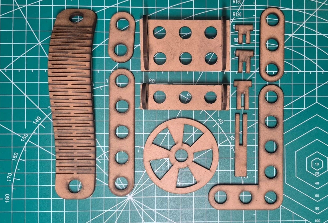
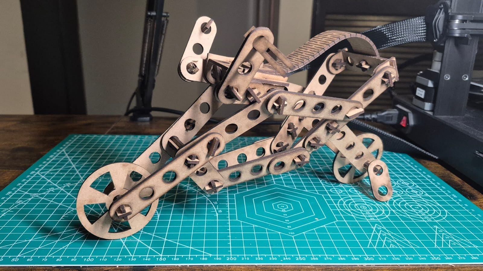
For the laser cutting, I drew inspiration from 3D metal puzzles, aiming to create a modular system. The work consists of a few pieces that were replicated to construct various figures. The entire modeling process was carried out in SolidWorks using global variables to dynamically adjust the material thickness, the number of joining points, the kerf, and the size of the piece.
Design Modular Pieces
 Beam
Beam
 Flexible Part
 Wheel
Wheel
 Joint
Joint
 Stake
Stake
Bean
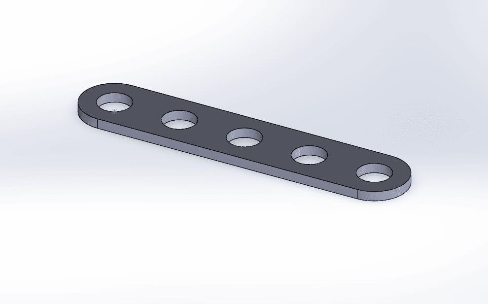
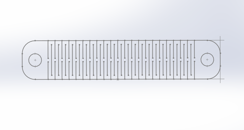
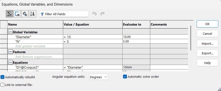
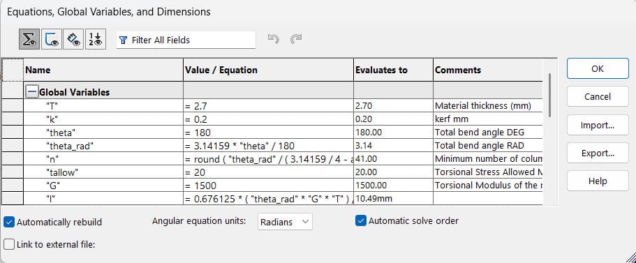
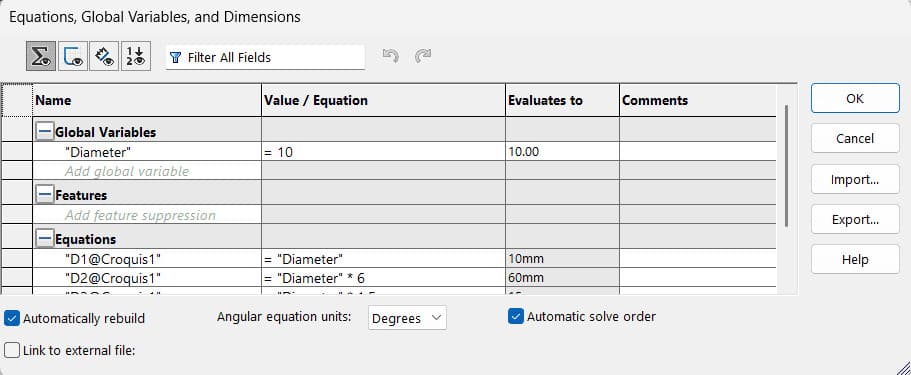
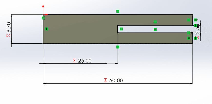
This piece is the base of the modular kit. This component functions as a linear structural beam. It features a series of regularly spaced slots that serve as universal attachment points. These openings allow other modules to be attached at varying intervals.
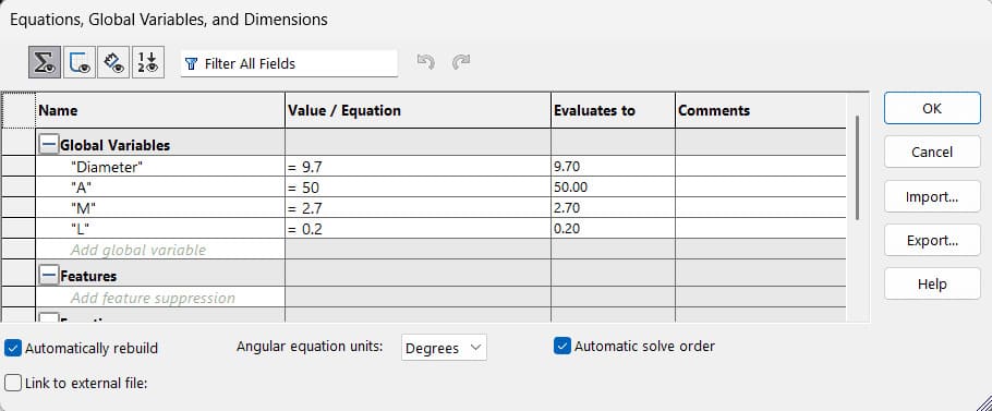
To make the part parametric, two variables were defined: Diameter of the attachment points and the number of these points. With these two variables, you can generate beams of any size you want.
Flexible Part
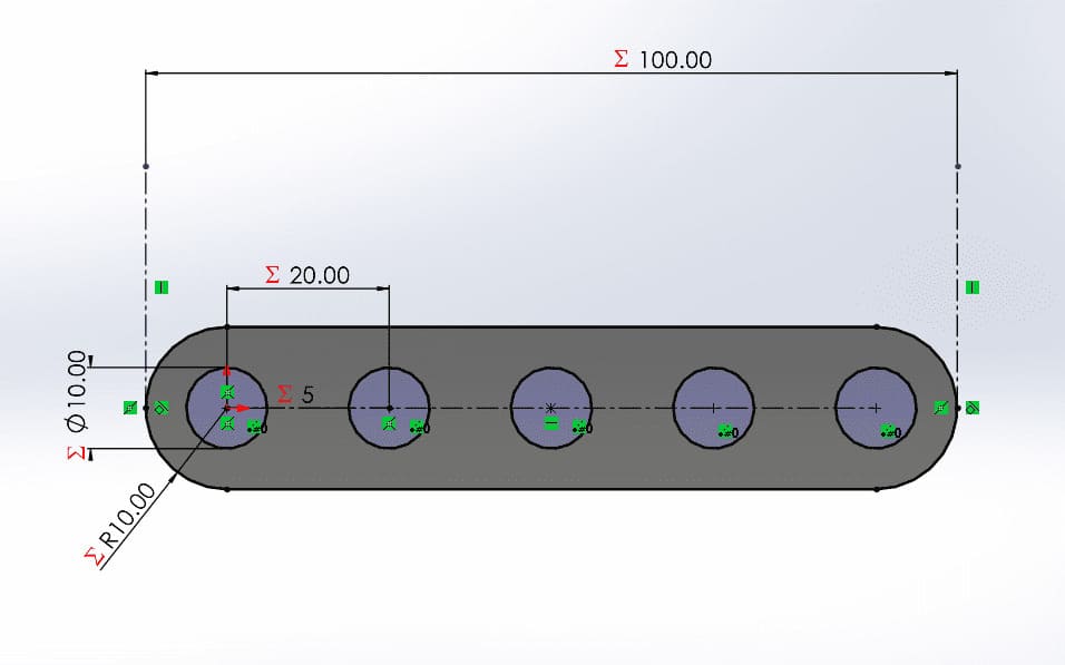
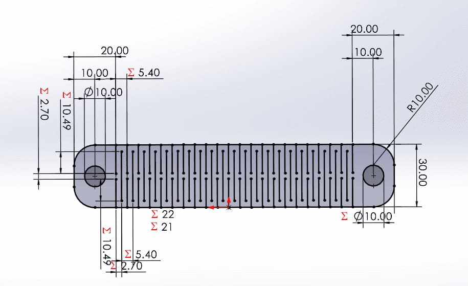
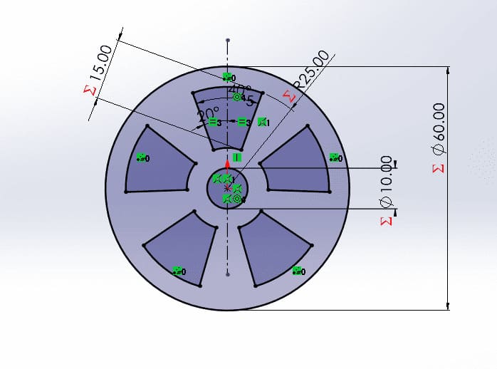
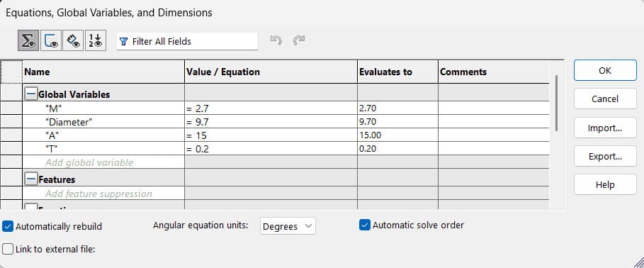
This part is designed to be flexible despite being made of MDF. This is achieved through cuts along the length of the piece, and two attachment points were also added, one on each side. The problem with this piece is that it becomes very fragile when its flex angle is exceeded.
Parameterization was essential because it allows control over the flexibility range. Variables and equations were defined so that simply changing the material thickness T, the kerf K, and the angle Theta modifies the entire part, forming the necessary cutting lines and adjusting the part width.
Wheel
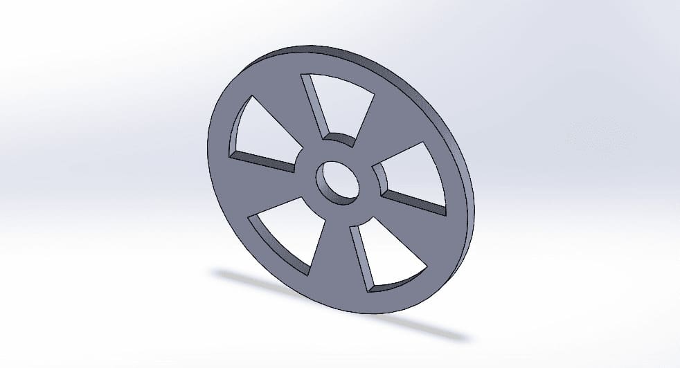
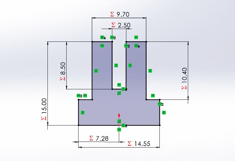
A wheel with a central mounting point. Essential for adding mobility and rotation, designed to fit all kinds of vehicles.
Parametric equations are used so that if you want to modify the attachment point of the center, the proportions are maintained.
Joint
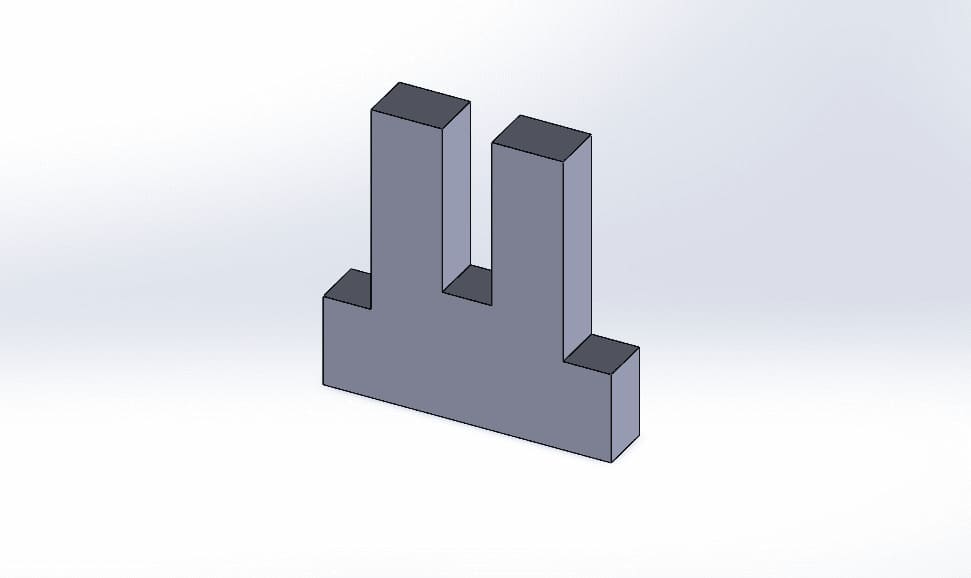
This connecting pin incorporates integrated mechanical stops designed to control the insertion depth. These small tabs prevent the pin from sliding completely into the connecting holes, ensuring precise alignment and securing the joined components.
The parametric equations were essential for the design of this piece, since it must fit perfectly as it is the piece that joins the others; the kerf, the thickness of the material and the number of pieces that it will join must be taken into account.
Stake
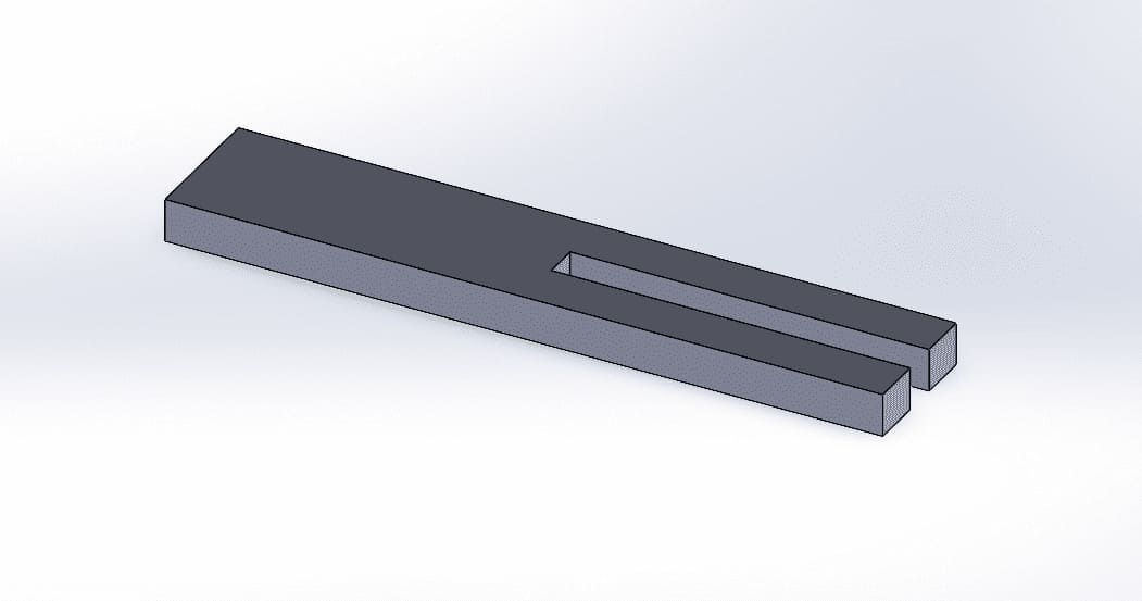
Designed as a shaft, this component features a uniform profile without mechanical stops. Its seamless design allows it to pass completely through the connecting holes, serving as a pivot point for rotating parts.
As with the pins that join the parts, parametric equations were essential for the shaft design, the diameter of the attachment points, the number of parts it will pass through, and the kerf must all be taken into account.
Laser Cutting Result
Laser Cutting Parameters
- Max. Power: 50%
- Min. Power: 45%
- Work Speed: 40mm/s
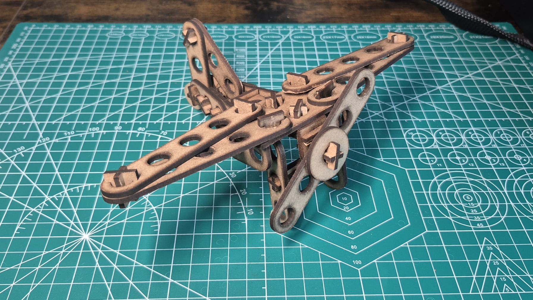
I believe my pieces could have been cut better, as the top part came out very charred and the bottom part didn't cut deep enough in certain places. My theory is that the laser wasn't at the correct height, however, the cut is functional.
Vinyl Cutting
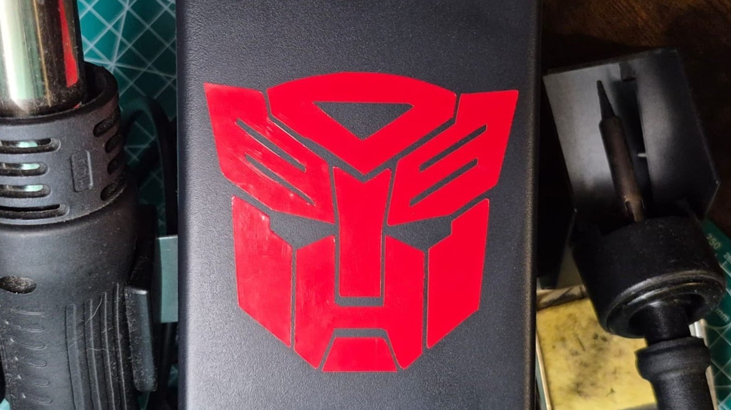
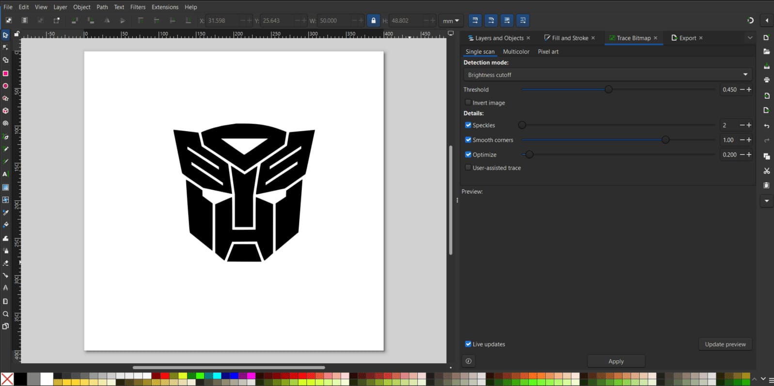
As part of my vinyl cutting practice, I took the Autobot symbol from Transformers and made it into a red vinyl sticker to decorate my soldering station.
To make the sticker, the image must be vectorized, and for this I used Inkscape software, since doing this with the Trace Bitmap tool is very quick and easy.
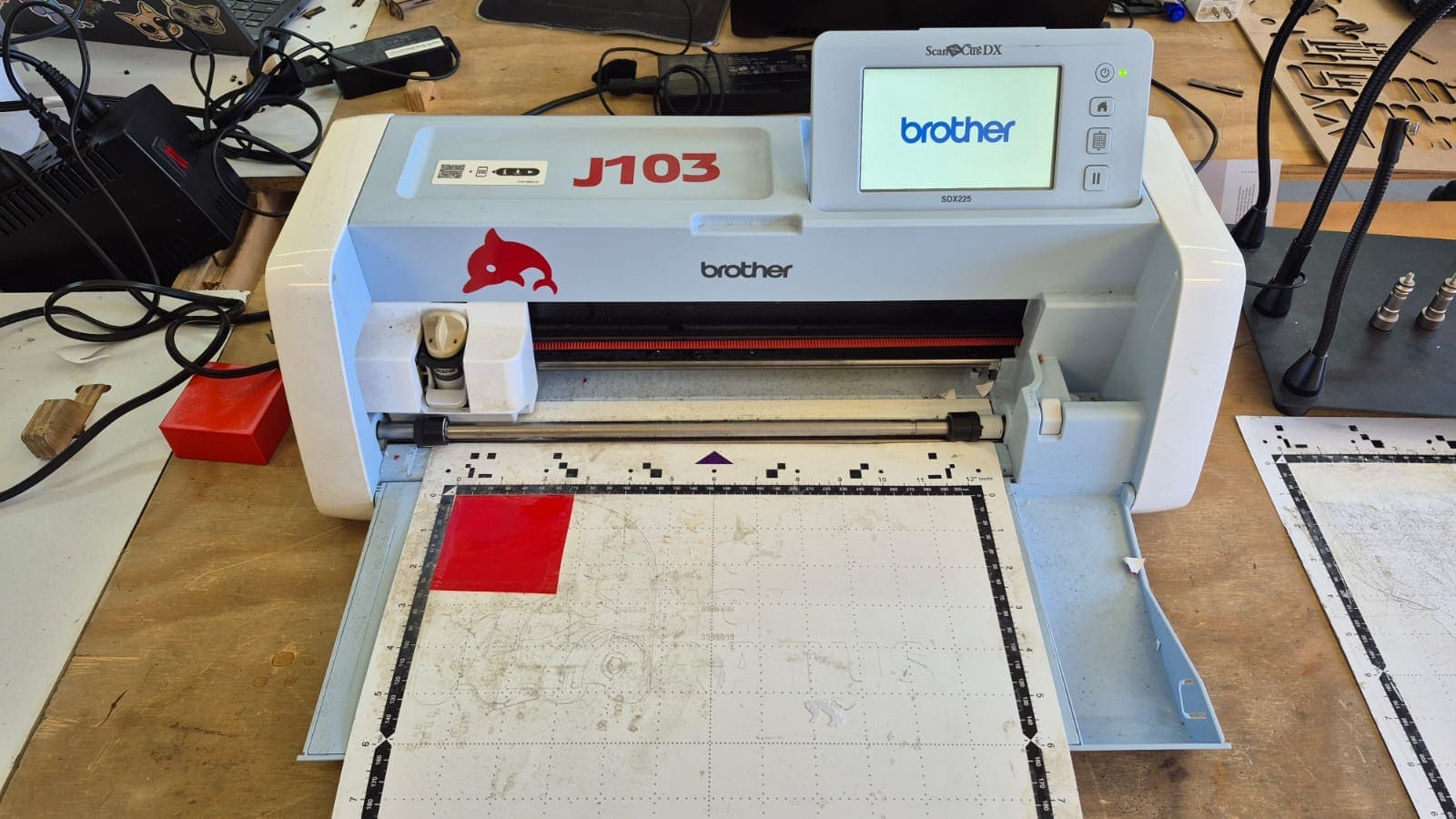
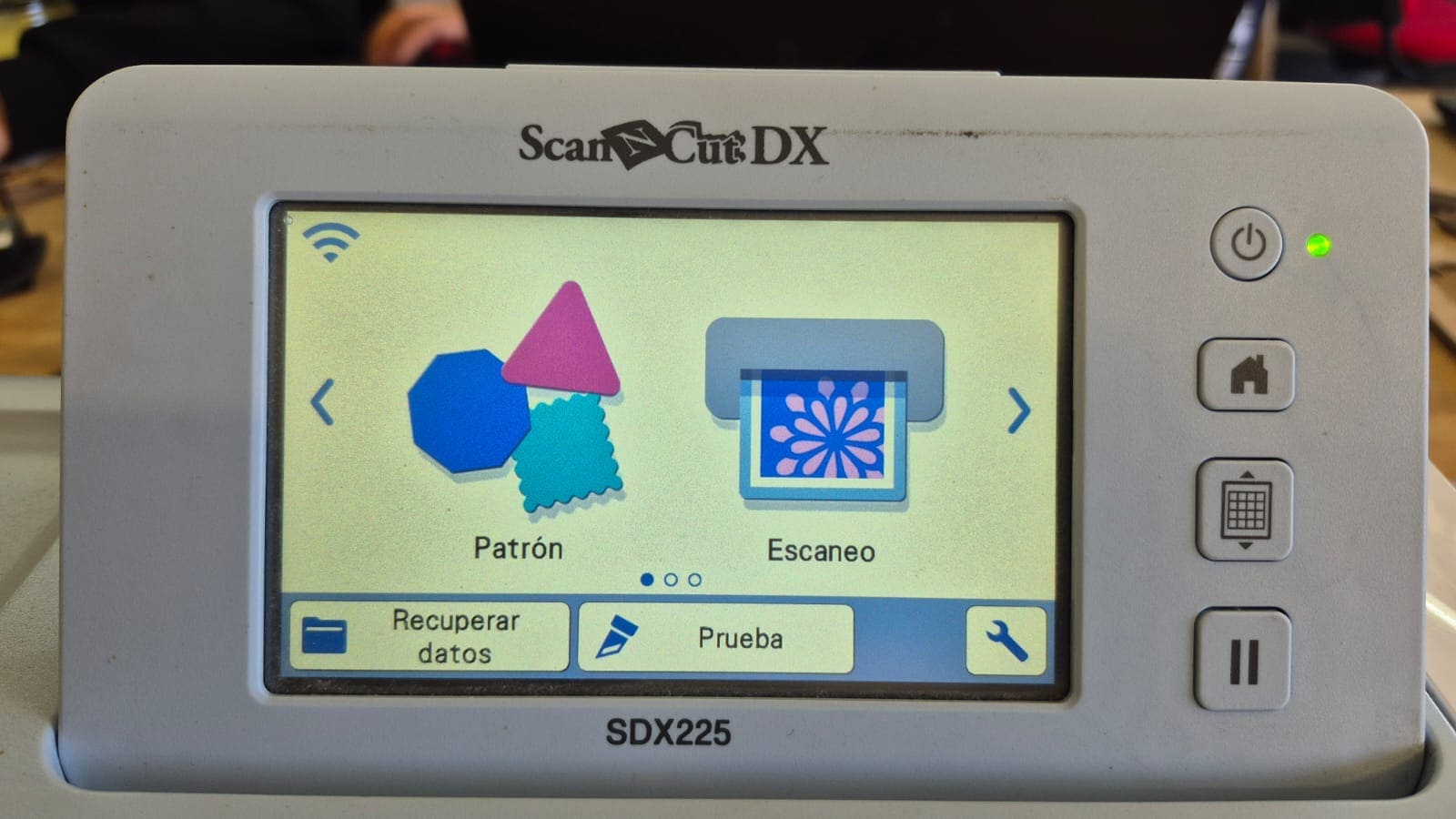
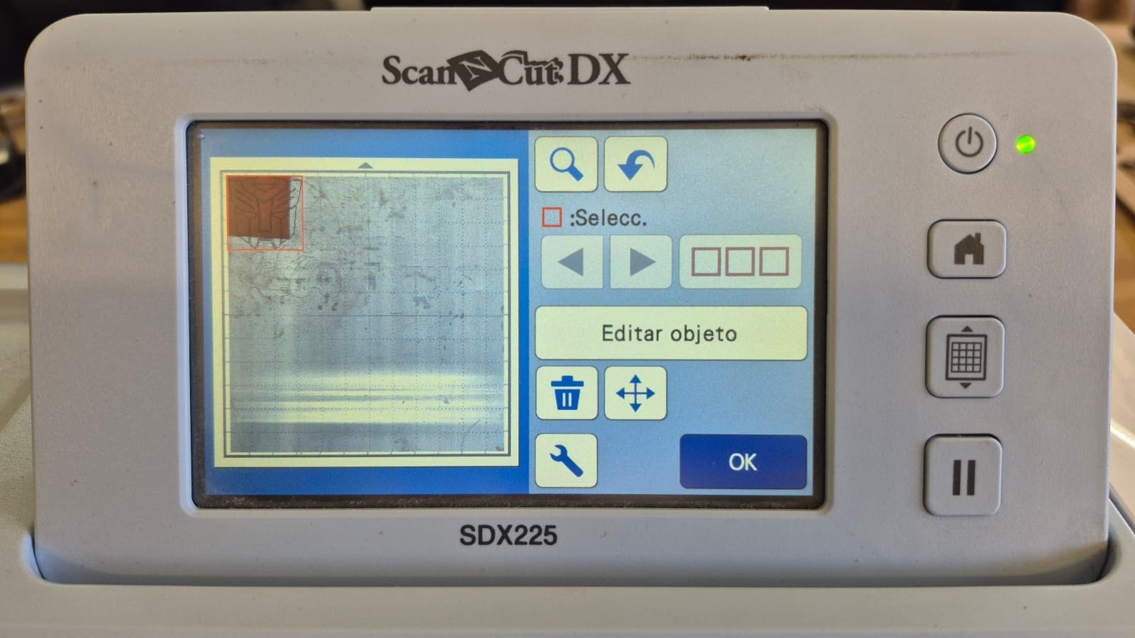
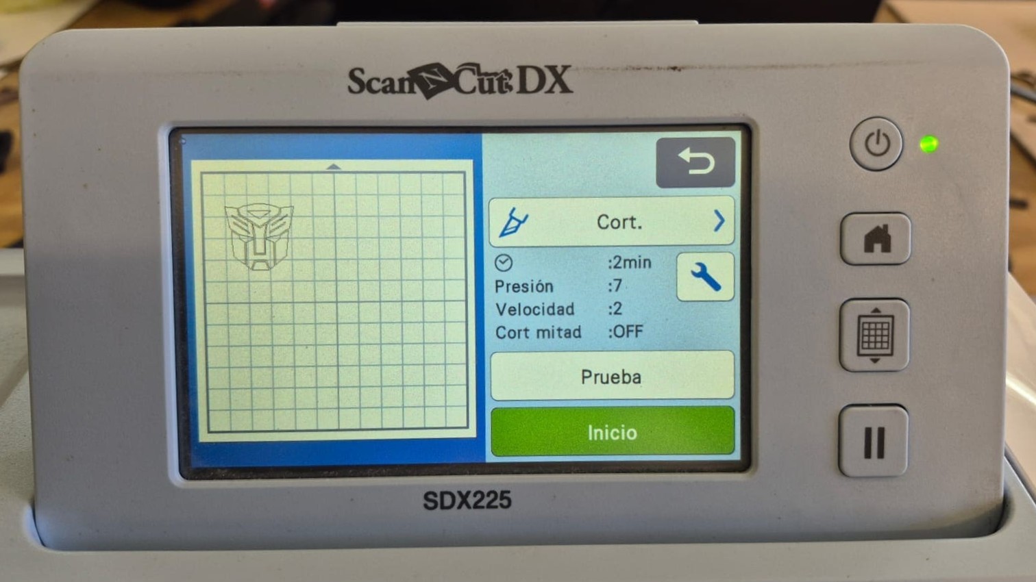
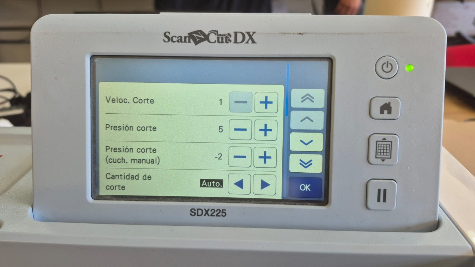
Using the Vinyl Cutter
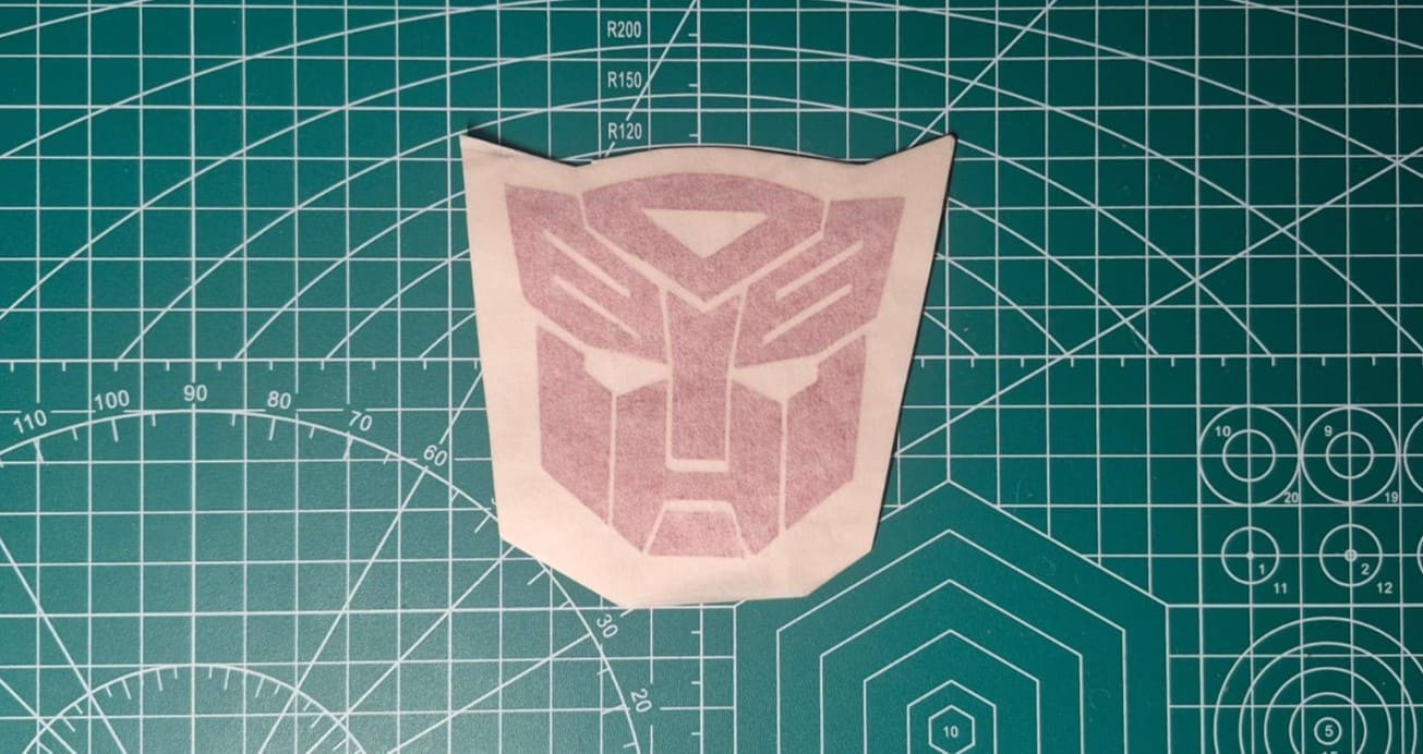
Vinyl Cutting Result
After cutting out the logo, I removed the parts of the vinyl that I wasn't going to use and used transfer paper so I could stick the sticker on without altering its shape.
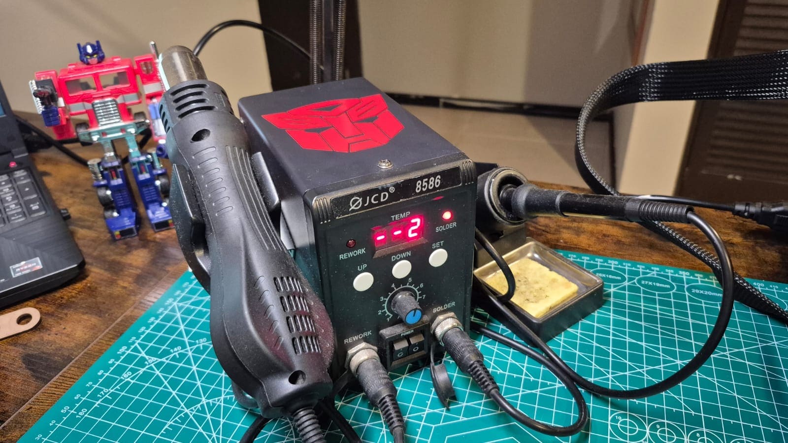
This was the final result after soldering on my soldering station: