

Week 11
Networking and Communications
Check out our Group Assignment to see how we connected two and more devices and what we learned about it GROUP PAGE →
// MAIN OBJECTIVE \\
Design, build and connect wired or wireless node(s) with network or bus addresses and a local input and/or output device(s).
My networking project
For this week, my goal is to connect to my microcontroller board. The purpose of this project is to learn how to test the wireless connection of my XIAO ESP32-C6 via Wi-Fi. This type of communication is crucial for making large projects because you need a proper connection to send and receive important data effectively.
My Setup
Hardware
This week is quite simple in terms of hardware because all I needed was my XIAO ESP32-C6. Testing the connections and logic directly with the built-in LED was enough to validate the architecture.
Note: the XIAO only works with a 2.4G network connection. Other types of networks, like 5G bands, won't work properly.
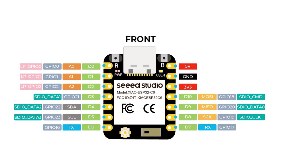
XIAO ESP32-C6 PINOUT.
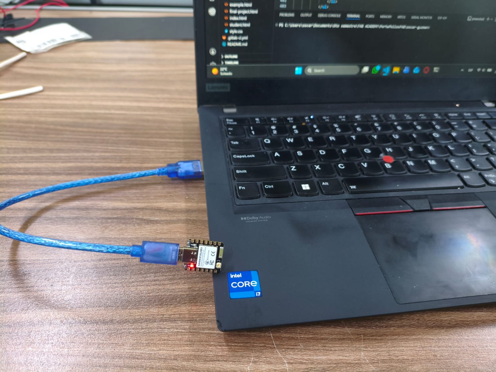
My networking setup.
Programming with ESP-IDF and C
The logic is simple: I first connect my XIAO to Wi-Fi, and then access a private Fab Academy server via an MQTT (Mosquitto) broker. This allows my board to publish data or subscribe to receive data. For this project, I subscribe the XIAO to a topic called CMD. From my PC or phone terminal, I can send a 1 or 0, which the XIAO receives to turn a LED on and off based on the command.
Logic and Libraries
Because I'm using ESP-IDF and pure C, this program relies on libraries like wifi_sta.h and mqtt_client_app.h to connect to the broker. I divided the functionality into separate files that the main program calls. This modular approach keeps the architecture clean.
The Role of FreeRTOS and Event Loops
In an embedded system like the ESP32-C6, we cannot let the main processor stall while waiting for a Wi-Fi connection or an incoming MQTT message. ESP-IDF utilizes FreeRTOS to handle background tasks effectively. Once the MQTT client is initialized, it runs on its own dedicated task and utilizes an event loop to notify the system when something important happens (like receiving a payload). This leaves the app_main function completely free to handle other hardware operations or simply execute a standard heartbeat delay.
Main Code
// main.c (ESP32-C6 / ESP-IDF)

#include <stdio.h>
#include "freertos/FreeRTOS.h"
#include "freertos/task.h"
#include "esp_err.h"
#include "esp_log.h"
#include "nvs_flash.h"
#include "wifi_sta.h"
#include "mqtt_client_app.h"

static const char *TAG = "APP_MAIN";

#ifndef WIFI_SSID
#define WIFI_SSID "YOUR_WIFI_2.4G_NAME"
#endif

#ifndef WIFI_PASS
#define WIFI_PASS "YOUR_PASSWORD"
#endif

#ifndef CONFIG_MQTT_BROKER_URI
#define CONFIG_MQTT_BROKER_URI "mqtt://mqtt.fabcloud.org:1883"
#endif

#define MQTT_USER "user"
#define MQTT_PASS "pass"

void app_main(void)
{
    ESP_LOGI(TAG, "Initializing system for ESP32-C6...");

    esp_err_t ret = nvs_flash_init();
    if (ret == ESP_ERR_NVS_NO_FREE_PAGES || ret == ESP_ERR_NVS_NEW_VERSION_FOUND) {
        ESP_ERROR_CHECK(nvs_flash_erase());
        ESP_ERROR_CHECK(nvs_flash_init());
    } else {
        ESP_ERROR_CHECK(ret);
    }

    const char *ssid = WIFI_SSID;
    const char *pass = WIFI_PASS;

    ESP_LOGI(TAG, "Connecting to Wi-Fi...");

    esp_err_t wifi_err = wifi_sta_connect(ssid, pass, 30000);
    if (wifi_err != ESP_OK) {
        ESP_LOGE(TAG, "Error connecting Wi-Fi");
        while (1) {
            vTaskDelay(pdMS_TO_TICKS(1000));
        }
    }

    ESP_LOGI(TAG, "Wi-Fi connected successfully");
    ESP_ERROR_CHECK(mqtt_app_start(CONFIG_MQTT_BROKER_URI, MQTT_USER, MQTT_PASS));

    while (1) {
        ESP_LOGI(TAG, "System working properly...");
        vTaskDelay(pdMS_TO_TICKS(10000));
    }
}
Understanding the MQTT and Memory Management
MQTT operates on a lightweight Publish/Subscribe model. The XIAO ESP32-C6 acts as a subscriber, listening to a specific topic. It relies entirely on the broker to route messages, meaning the sending and receiving devices never connect directly to each other.
When a message is published to the topic from a terminal, the broker pushes the data to the microcontroller, triggering an MQTT_EVENT_DATA inside our event handler. A critical detail when programming in C with ESP-IDF is memory safety. The incoming payload from MQTT is not necessarily a null-terminated string. Therefore, we must use secure functions like strncmp to evaluate the exact payload length. Using a standard string comparison without length limits could result in reading unauthorized memory spaces or causing a core panic on the ESP32.
// Snippet from mqtt_client_app.c inside the mqtt_event_handler function

case MQTT_EVENT_DATA:
    ESP_LOGI(TAG, "MQTT_EVENT_DATA received");

    if (strncmp(event->data, "1", event->data_len) == 0) {
        gpio_set_level(BLINK_GPIO, 1);
    }
    else if (strncmp(event->data, "0", event->data_len) == 0) {
        gpio_set_level(BLINK_GPIO, 0);
    }
    break;
Note: all the other codes like .c or .h will be included in the download files above.
Final Result
Here is a video demonstrating the operation of the XIAO connecting to Wi-Fi and turning a LED on and off with the MQTT broker.
Final demonstration of the connection between XIAO and PC or Phone.
Files
Here you can download the original files generated for this week's project: