

Week 04
Embedded Programming
// MAIN OBJECTIVE \\
The goal of this week is to understand the fundamentals of embedded programming by learning how the C and Python programming language works inside a microcontroller. We will learn to evaluate essential board data like the operating voltage, clock speed, memory capacity, etc. for our projects, and write code to control stuff and read sensors.
If you want to see our Group Assignment for this week, click HERE →
Microcontroller Selection: Analyzing the Specs
Before writing any code, it is crucial to understand the hardware. When reviewing microcontrollers, we need to check the datasheet because it is crucial for knowing electronics specs like:
- Clock Speed: How fast the processor executes instructions (measured in MHz).
- Operating Voltage: The logic level voltage (usually 3.3V or 5V).
- Architecture: The design of the processor (AVR, ARM Cortex, RISC-V).
- Memory (SRAM & Flash): SRAM is for active variables during runtime, while Flash stores the actual compiled code.
For this assignment, I chose the Raspberry Pi Pico 2. If you want to check its detailed technical specifications, you can read the official Pico 2 Datasheet →.
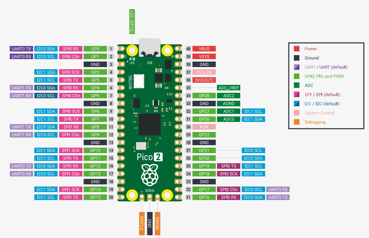
Raspberry Pi Pico 2 PinOut.
To demonstrate why it is a great choice, let's compare it against one similar chip (in size), the Arduino Nano:
| Specification | Raspberry Pi Pico 2 | Arduino Nano |
|---|---|---|
| Microcontroller Chip | RP2350 | ATmega328P |
| Architecture | Dual ARM Cortex-M33 / RISC-V | 8-bit AVR |
| Clock Speed | 150 MHz | 16 MHz |
| Operating Voltage | 3.3V | 5V |
| SRAM | 520 KB | 2 KB |
| Flash Memory | 4 MB | 32 KB |
As the data shows, the Pico 2 is significantly more powerful, offering nearly 10 times the clock speed and massively more memory, making it ideal for complex mathematical operations and real-time sensor processing.
Setting up the Environment
Programming Software
To write the C code, I am using Visual Studio Code, the exact same environment I'm using to build this website. While the Arduino IDE is great for beginners, VS Code offers major professional advantages like:
- IntelliSense: Smart autocomplete for C/C++ syntax and library functions, which speeds up coding a lot.
- Integrated Git: It is confortable to modify the website and push it directly to my FabAcademy repository with the same software.
- Advanced Debugging: Better terminal integration and error tracking tools.
- Programming Potential: This software has the tools for optimizing code and implementing advance functions to the microcontrollers.
Understanding GPIO and I2C (SDA/SCL)
To connect the Pico 2 and execute instructions, we use GPIO (General Purpose Input/Output) pins. These pins can send out electrical signals (like turning on an LED) or read incoming signals (like reading a button press or sensor data).
For this exercise, I am using an MPU6050 sensor, which contains a 3-axis accelerometer and a 3-axis gyroscope to measure angles in real-time. To communicate with it, we don't just use standard digital high/low signals; we use the I2C protocol.
I2C uses only two wires: SDA (Serial Data) to send the actual data bits back and forth, and SCL (Serial Clock) to keep the devices perfectly synchronized. I used I2C because the MPU6050 generates massive amounts of data; using SDA/SCL allows us to reliably retrieve 6 different axes of movement simultaneously using only two GPIO pins on the Pico 2, saving the rest of the pins for other components.
For programming in SDK Pico (Visual Studio and C), we mainly need 2 archives for making the program work: The CmakeLists.txt which contains all the basic configurations for initializing the Pico, implementing libraries, connecting the Serial Monitor, etc.. And the main.c the file in which all the C code is stored.
The Code: Reading Real-Time Angles
Below is the C code and the CmakeLists.txt written in VS Code. It initializes the I2C communication on the Pico 2, wakes up the MPU6050, and continuously reads the raw gyroscope and accelerometer data to calculate the real-time angles of the sensor.
MAIN.C
#include#include #include "pico/stdlib.h" #include "hardware/i2c.h" #include "hardware/timer.h" #define I2C_PORT i2c0 #define SDA_PIN 4 #define SCL_PIN 5 #define MPU6050_ADDR 0x68 #define REG_PWR_MGMT_1 0x6B #define REG_ACCEL_XOUT_H 0x3B #define ACCEL_SENS 16384.0f #define GYRO_SENS 131.0f void mpu6050_init() { uint8_t buf[2]; buf[0] = REG_PWR_MGMT_1; buf[1] = 0x80; i2c_write_blocking(I2C_PORT, MPU6050_ADDR, buf, 2, false); sleep_ms(100); buf[0] = REG_PWR_MGMT_1; buf[1] = 0x01; i2c_write_blocking(I2C_PORT, MPU6050_ADDR, buf, 2, false); sleep_ms(100); } int main() { stdio_init_all(); i2c_init(I2C_PORT, 400 * 1000); gpio_set_function(SDA_PIN, GPIO_FUNC_I2C); gpio_set_function(SCL_PIN, GPIO_FUNC_I2C); gpio_pull_up(SDA_PIN); gpio_pull_up(SCL_PIN); sleep_ms(2000); printf("Inicializando MPU6050...\n"); mpu6050_init(); uint8_t buffer[14]; float roll = 0.0f, pitch = 0.0f, yaw = 0.0f; uint32_t last_time = time_us_32(); while (1) { uint8_t val = REG_ACCEL_XOUT_H; int ret_write = i2c_write_timeout_us(I2C_PORT, MPU6050_ADDR, &val, 1, true, 10000); int ret_read = i2c_read_timeout_us(I2C_PORT, MPU6050_ADDR, buffer, 14, false, 10000); if (ret_read == 14 && ret_write == 1) { int16_t accel_x = (buffer[0] << 8) | buffer[1]; int16_t accel_y = (buffer[2] << 8) | buffer[3]; int16_t accel_z = (buffer[4] << 8) | buffer[5]; int16_t gyro_x = (buffer[8] << 8) | buffer[9]; int16_t gyro_y = (buffer[10] << 8) | buffer[11]; int16_t gyro_z = (buffer[12] << 8) | buffer[13]; float ax = accel_x / ACCEL_SENS; float ay = accel_y / ACCEL_SENS; float az = accel_z / ACCEL_SENS; float gx = gyro_x / GYRO_SENS; float gy = gyro_y / GYRO_SENS; float gz = gyro_z / GYRO_SENS; uint32_t current_time = time_us_32(); float dt = (current_time - last_time) / 1000000.0f; last_time = current_time; if (dt > 0.1f) dt = 0.01f; float accel_pitch = atan2(-ax, sqrt(ay * ay + az * az)) * 180.0 / M_PI; float accel_roll = atan2(ay, az) * 180.0 / M_PI; pitch = 0.98f * (pitch + gy * dt) + 0.02f * accel_pitch; roll = 0.98f * (roll + gx * dt) + 0.02f * accel_roll; yaw += gz * dt; printf("X (Roll): %6.2f | Y (Pitch): %6.2f | Z (Yaw): %6.2f\n", roll, pitch, yaw); } else { printf("Error I2C: Recuperando comunicación con MPU6050...\n"); mpu6050_init(); last_time = time_us_32(); } sleep_ms(10); } return 0; }
CmakeLists.txt
            # Generated Cmake Pico project file

cmake_minimum_required(VERSION 3.13)

set(CMAKE_C_STANDARD 11)
set(CMAKE_CXX_STANDARD 17)
set(CMAKE_EXPORT_COMPILE_COMMANDS ON)

# Initialise pico_sdk from installed location
# (note this can come from environment, CMake cache etc)

# == DO NOT EDIT THE FOLLOWING LINES for the Raspberry Pi Pico VS Code Extension to work ==
if(WIN32)
    set(USERHOME $ENV{USERPROFILE})
else()
    set(USERHOME $ENV{HOME})
endif()
set(sdkVersion 2.2.0)
set(toolchainVersion 14_2_Rel1)
set(picotoolVersion 2.2.0-a4)
set(picoVscode ${USERHOME}/.pico-sdk/cmake/pico-vscode.cmake)
if (EXISTS ${picoVscode})
    include(${picoVscode})
endif()
# ====================================================================================
set(PICO_BOARD pico2 CACHE STRING "Board type")

# Pull in Raspberry Pi Pico SDK (must be before project)
include(pico_sdk_import.cmake)

project(MpuFAB C CXX ASM)

# Initialise the Raspberry Pi Pico SDK
pico_sdk_init()

# Add executable. Default name is the project name, version 0.1

add_executable(MpuFAB MpuFAB.c )

pico_set_program_name(MpuFAB "MpuFAB")
pico_set_program_version(MpuFAB "0.1")

# Modify the below lines to enable/disable output over UART/USB
pico_enable_stdio_uart(MpuFAB 0)
pico_enable_stdio_usb(MpuFAB 1)

# Add the standard library to the build
target_link_libraries(MpuFAB
        pico_stdlib
        hardware_i2c
        m
        )

# Add the standard include files to the build
target_include_directories(MpuFAB PRIVATE
        ${CMAKE_CURRENT_LIST_DIR}
)

pico_add_extra_outputs(MpuFAB)
Demonstration and Hero shots
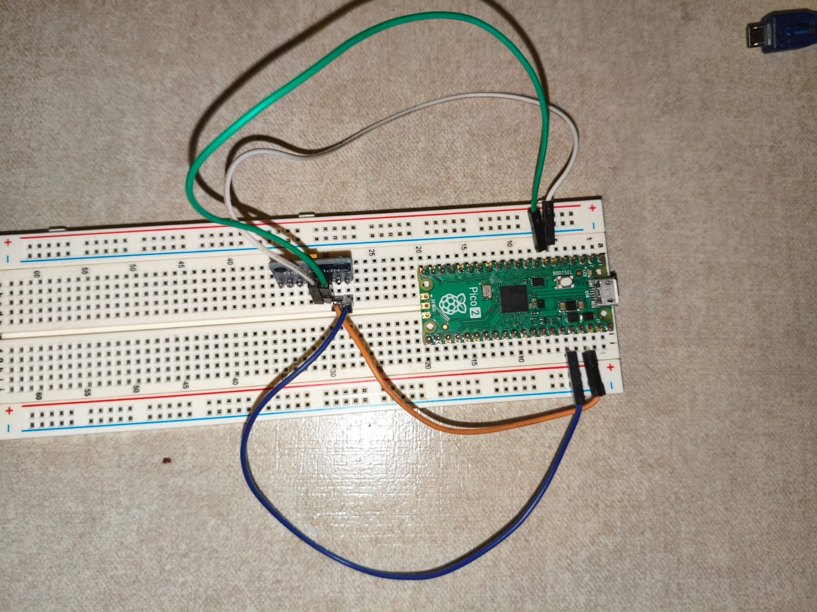
RPP2 and MPU6050 Hero shot.
In the following video, you can see the serial monitor printing the angles in real-time as I physically tilt the MPU6050 sensor connected to the Pico 2.
Final result.
Conclusion
This week was incredibly useful for starting professional coding using VS Code and C. The decision to execute this specific exercise with the Pico 2 and the MPU6050 is a direct step forward for my Final Project → implementing this calculus for making the math for my handmade V-Tol. By successfully mastering the I2C protocol to read real-time angle data, I now have the core navigation logic ready to start doing calculus.
Files
Here you can download the original files I used for this week's assignments: