3D Design
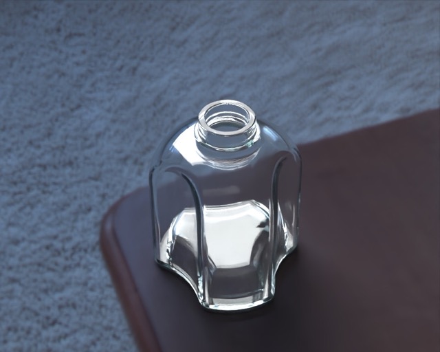
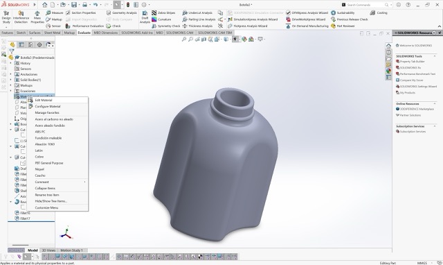
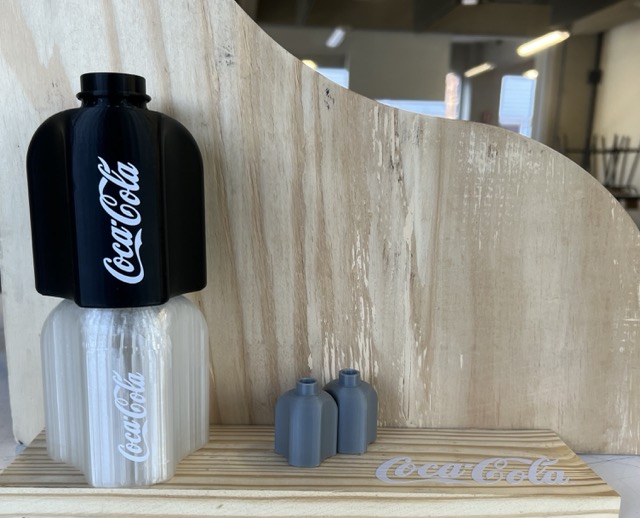
For this week's assignment, I designed a modular bottle in SolidWorks.
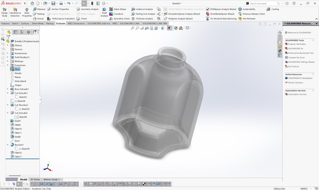
Why This Geometry Requires 3D Printing
My design features an internal hollow cavity and internal threading to allow the modular components to attach seamlessly. This specific geometry cannot be easily manufactured using subtractive methods, like a 3-axis CNC milling machine. A milling bit simply cannot reach inside a solid block to hollow it out or create internal overhangs without cutting the object into multiple pieces first.
Conclusion
3D printing (additive manufacturing) is the ideal and necessary method to build this object layer by layer, making it possible to achieve internal threading and hollow cavities in a single print.
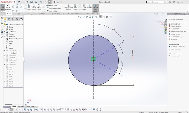
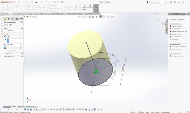
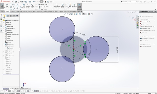
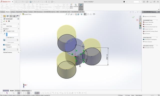
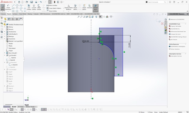
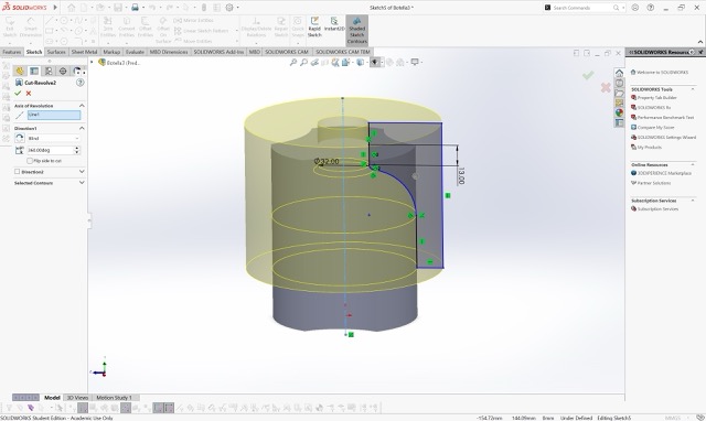
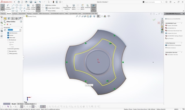
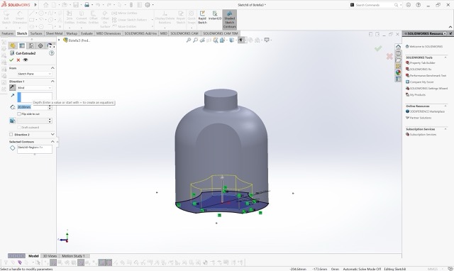
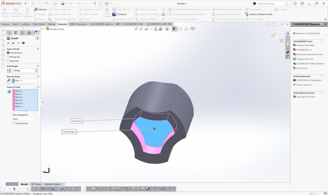
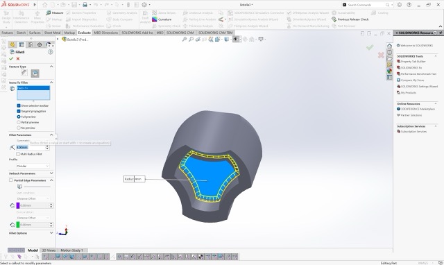
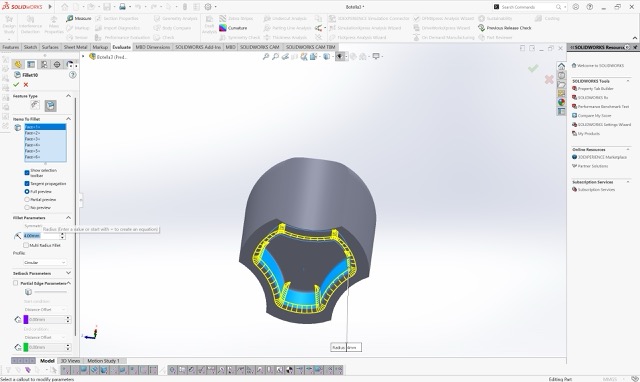
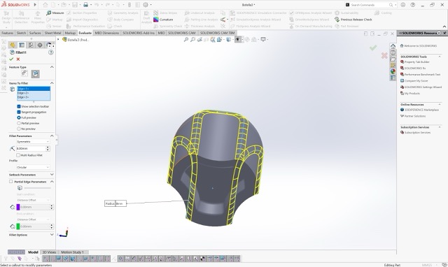
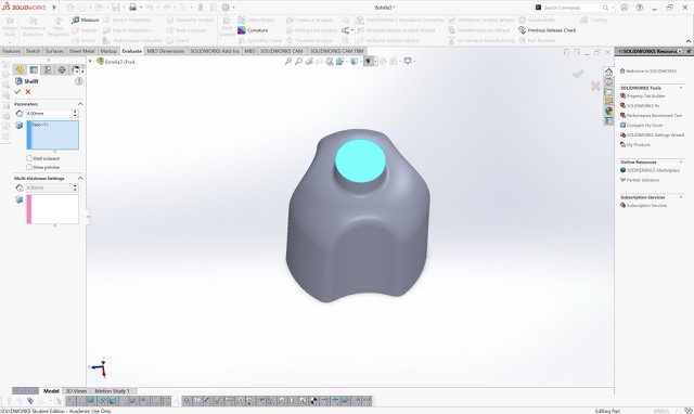
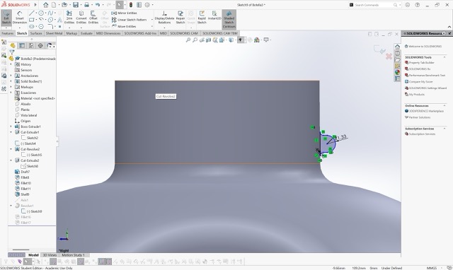
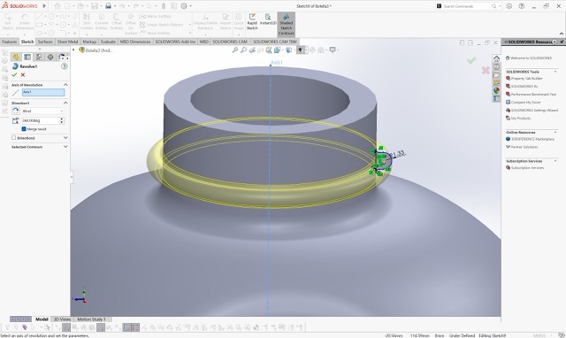
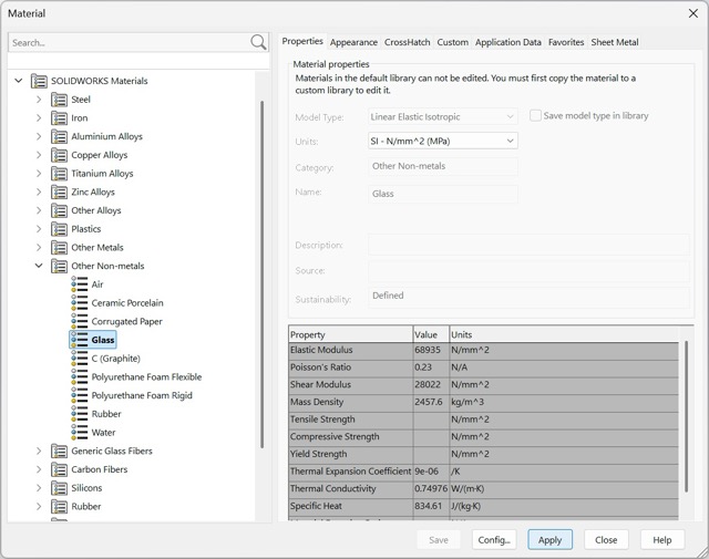
SolidWorks — Modular Bottle Design
Slide through to see the full step-by-step process of how I modeled the bottle from scratch.
3D Printing
This week I printed my design for a modular bottle. You can find how I modeled it in my 3D Modeling section.
Key Design Rules from Machine Testing
Testing the 3D printers helped me understand the physical limits of our machines and establish key design rules.
Overhang Limit
The recommended maximum overhang without support is 45°; beyond that, support structures are necessary.
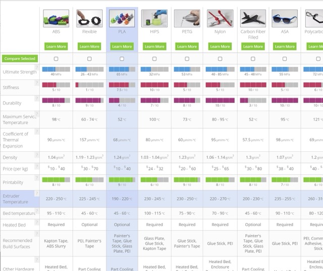
Material Temperatures
Different materials require specific extruder and bed temperatures to print successfully.
Tolerance for Moving Parts
Moving parts or interlocking pieces need a clearance gap of around 0.14 mm to fit together properly after printing.
Pros & Cons Based on This Week's Workflow
✓ Advantages
- Rapid Prototyping: Design, print, and test a part on the exact same day.
- Complex Geometries: Easily creates internal cavities and intricate shapes impossible with subtractive methods.
- Less Material Waste: Only uses the exact amount of plastic needed, unlike milling which cuts away from a solid block.
✗ Limitations
- Slow for Mass Production: Printing takes hours, highly inefficient compared to injection molding.
- Directional Weakness: Parts are structurally weaker along the Z-axis (layer bonds) and can snap under stress.
- Post-Processing: Often requires removing supports, sanding, or smoothing after printing.
Step-by-Step: Installing and Configuring UltiMaker Cura
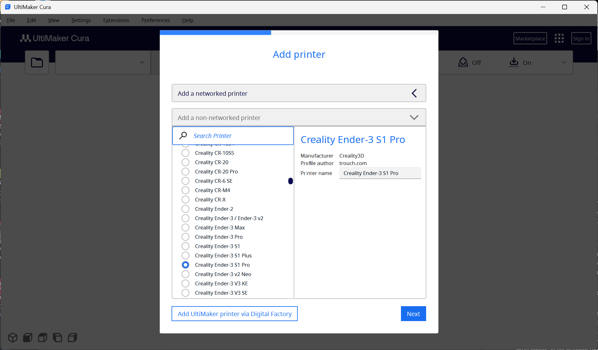
Installing & Adding the Printer
I downloaded UltiMaker Cura and selected the option to add a Non-Ultimaker printer. Then I searched for the Creality Ender-3 S1 Pro available in our lab and selected it.
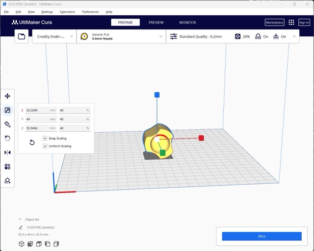
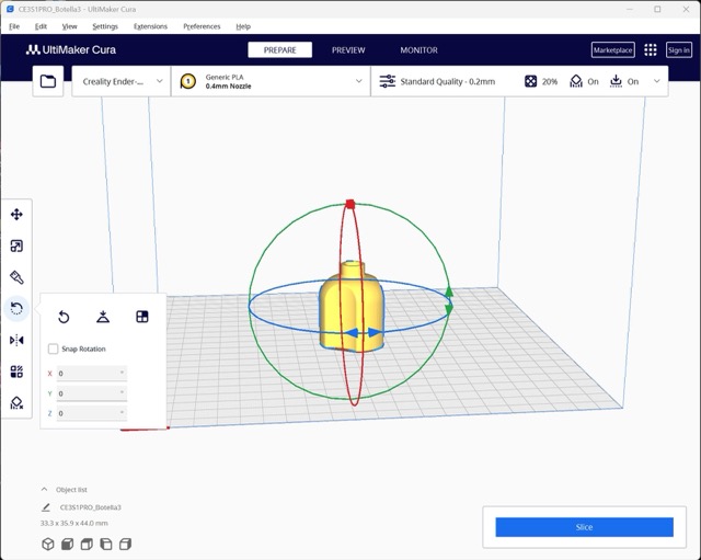
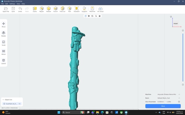
Importing & Positioning the Model
I imported the STL file by dragging it into Cura. I scaled and rotated the model to position it the way I wanted for printing. Click "Standard Quality" to open the settings panel.
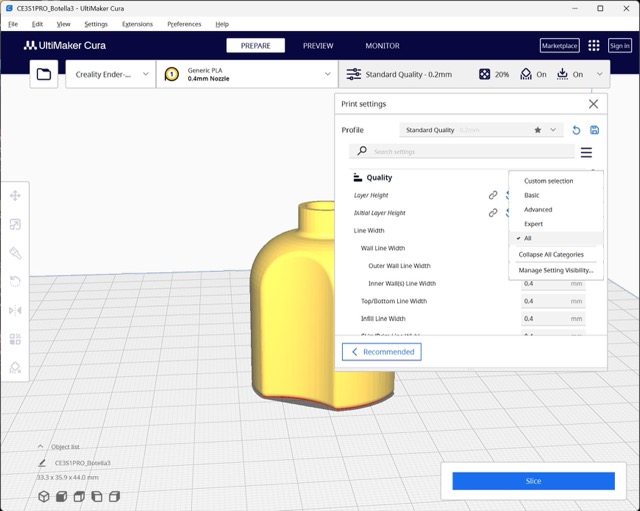
Quality — Layer Height
I set the Layer Height to 0.25 mm. My instructor recommended not exceeding 80% of the nozzle diameter. With a 0.4 mm nozzle, the maximum is 0.32 mm. Good quality falls between 0.22 mm and 0.27 mm.
Walls — Wall Line Count
The number of walls determines how rigid your piece will be. I set the Wall Line Count to 2 because my piece was small. More walls = more rigidity.
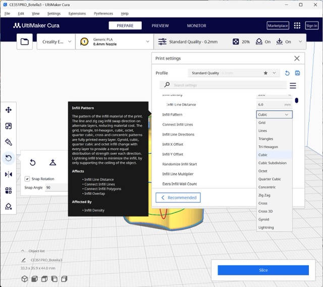
Infill Density
Our instructor recommended keeping the infill density between 10%–20%. You can also experiment with different infill patterns depending on your structural needs.
Material & Temperature
I used Generic PLA and set the extruder temperature to 200°C as recommended. For other materials, refer to the Simplify3D Materials Guide.
Print Speed
For good quality, the recommended speed range is 60–100 mm/s. Since I wanted the print to be faster, I set the speed to 100 mm/s.
Support Structures
Some parts require support due to their geometry. There are two types: Tree supports and Standard supports. I personally prefer tree supports because I find them easier to remove after printing.
Build Plate Adhesion
To prevent detachment from the bed, use build plate adhesion. The three options are: Skirt (cleans the nozzle), Brim (thin outer layer for better grip), and Raft (solid base layer). I used Raft since my structure was not very complicated.
Preview & Slicing
To see how your print will look, click "Preview" — if it doesn't work, click "Slice" first. In this section you can see the estimated printing time and grams of filament required.
From SD Card to Printed Part
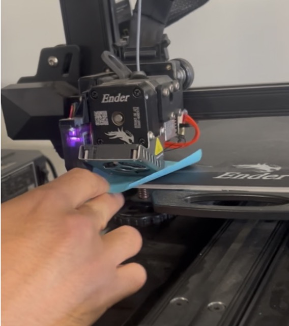
Save G-code & Calibrate
After slicing, I saved the G-code file onto a micro SD card and inserted it into the printer. I calibrated the machine using a Post-it note — ensuring it moved with slight resistance between the nozzle and the build plate.
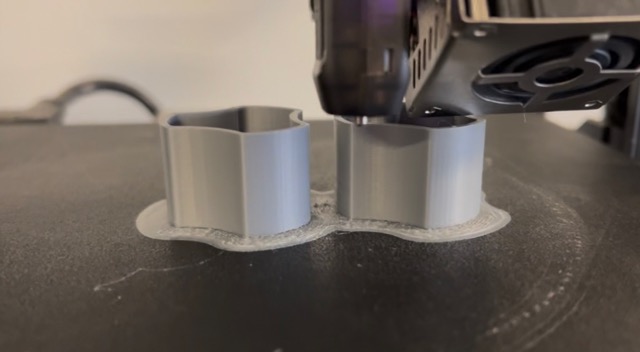
Start the Print
I pressed play, and the machine started printing. The Raft adhesion layer went down first, followed by the model itself.
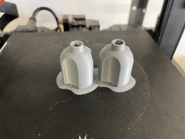
Final Result
Here are the finished prints after removing the raft and support structures.
3D Scanning
3D scanning is the process of analyzing a real-world object to collect data on its exact shape. The scanner projects patterns of light onto the object and cameras measure how that light deforms over the surface. The software then calculates this data to generate a highly detailed digital 3D replica (a mesh) composed of thousands of polygons.
Applications of 3D Scanning
Reverse Engineering
Scan an existing part to bring it into CAD and modify it without modeling from scratch.
Custom Fit Accessories
Design accessories that must fit perfectly onto a physical object by scanning it first.
Digital Archiving
Create precise digital replicas of real-world items for documentation, modification, or 3D printing.
Step-by-Step: Scanning a Pen with Einscan
How to use the Shining 3D Scanner
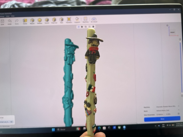
Slide to see how I scanned this pen — from setup to final mesh.
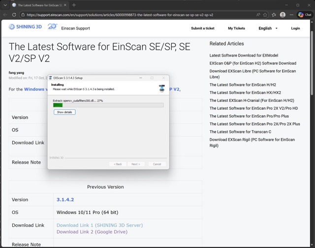
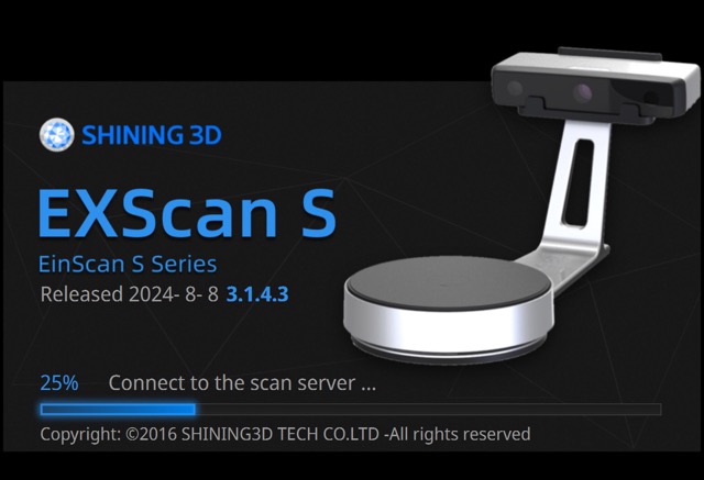
Step 1 — Download Einscan
First I downloaded the Einscan app, which is the proprietary software for the Shining 3D scanner.
Step 2 — Connect the Scanner
Before opening the app, turn the scanner on and connect it to your computer via USB.
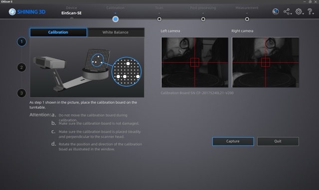
Step 3 — Calibrate
Start the calibration process. Pay close attention to the instructions and watch the indicator images closely to ensure accuracy.
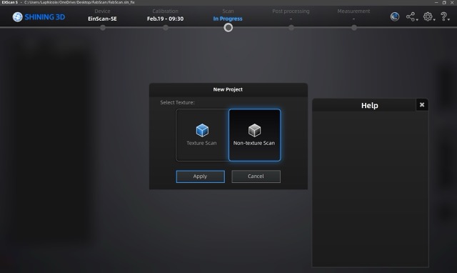
Step 4 — Select Scan Mode
Select the Non-Textured Scan mode, which is best for capturing precise geometry without color data.
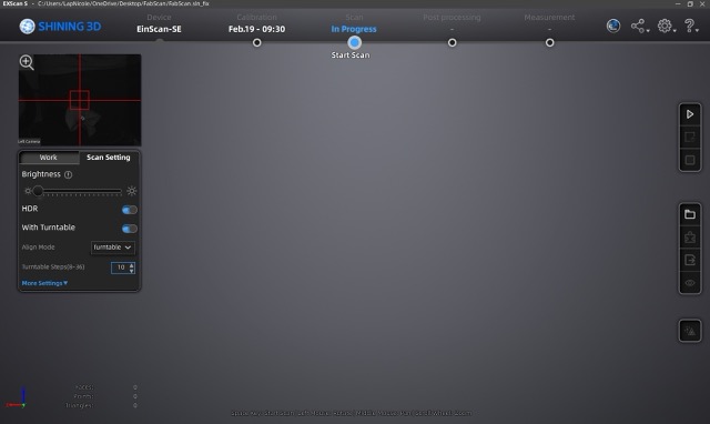
Step 5 — Place Object & Start
Place the object on the scanner turntable, turn off HDR, then click Start to begin the automatic rotation scan.
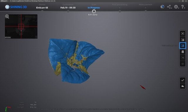
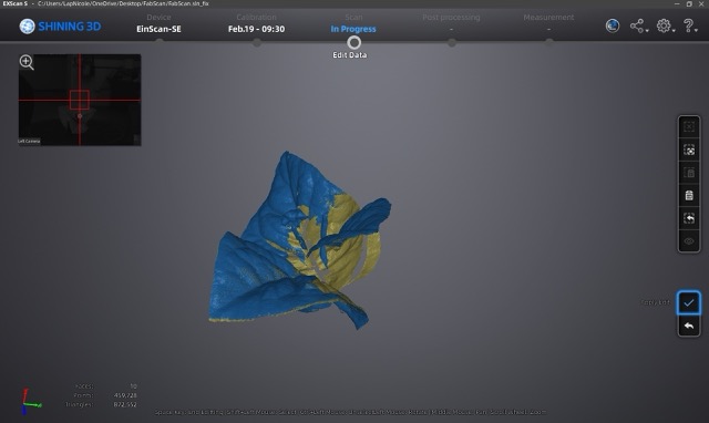
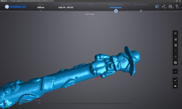
Step 6 — Review & Clean Stray Points
When the rotation finishes, inspect the scan. If unwanted floating points appear, hold Shift, select them, then click Delete Selection to remove them.
Step 7 — Confirm the Scan
Click the checkmark to confirm and accept the current scan pass.
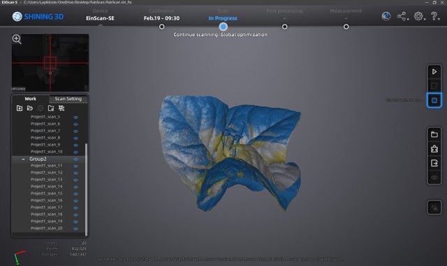
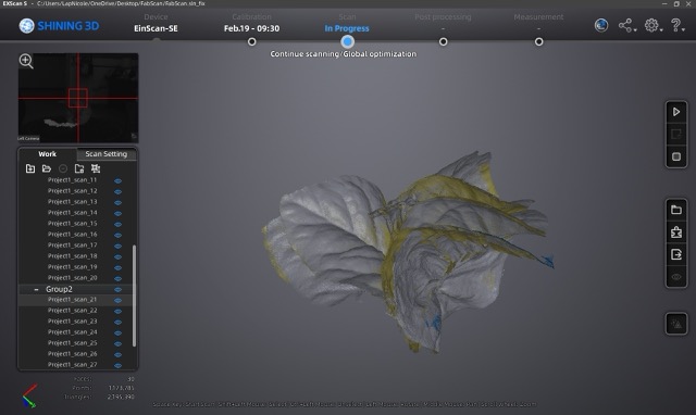
Step 8 — Global Optimization & Second Pass
Click Global Optimization and reposition the object to scan any areas that were missed in the first pass.
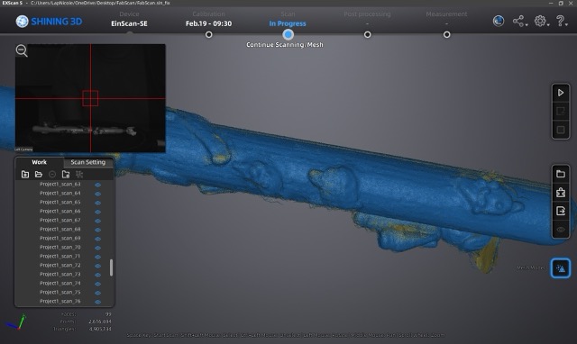
Step 9 — Generate Mesh
Once you are satisfied with all scan passes, click Mesh Model to process the raw point cloud into a 3D mesh.
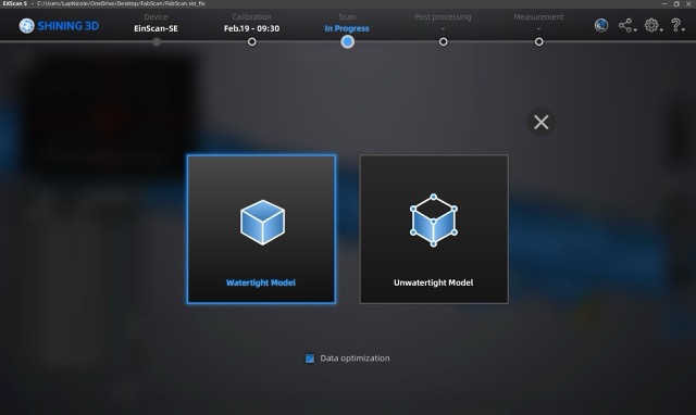
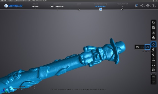
Step 10 — Choose Watertight Model
Select the Watertight Model option. This creates a fully closed mesh with no holes, which is essential for 3D printing.
Step 11 — Clean the Model
Fix imperfections directly in the app: hold Shift, select the problem area, and click Delete Selection (second icon in the control bar). Then click the checkmark.
Step 12 — Fill Holes
Use the Automatic Fill tool to close any remaining holes in the mesh. You can also fill them manually for more control.
Final Result
The completed, cleaned watertight mesh of the scanned pen — ready to export as STL for 3D printing or CAD import.
Files
Here you can download all my original files for this week's tasks.
Original Design Files
Modular Bottle
STL print-Ready File
Scanned Pen — Cleaned Watertight Mesh
Einscan output, cleaned and hole-filled in Einscan software
Tips and mistakes
Problems encountered:
I started by scanning a flower, but since it was a fixed solid object, when I moved it to scan different sides, the model became distorted and more petals appeared overlapping.
I also had a problem with the pen, as it had a glossy finish and several parts did not scan.
How I solved them:
To solve the first problem I had no choice but to change the object, and for the second one what I did was put on some makeup shadow that it came with so that the surface was no longer shiny.