3. Computer-controlled cutting
Group assignment
link to the group assignmentDuring this week I learned how to use equations on solid Works and how to use the laser and vinyl cutter.
Laser cutting
Equations
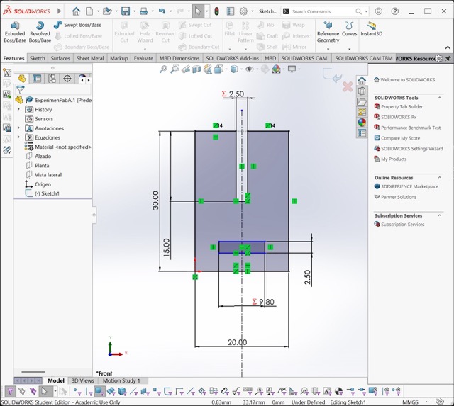
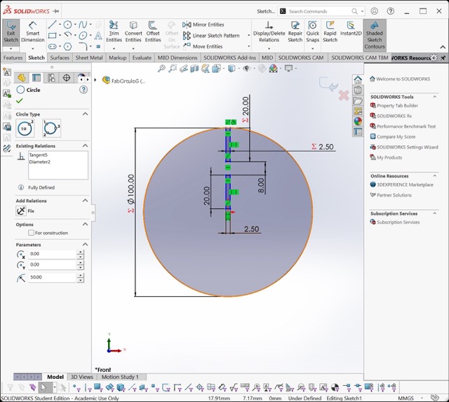
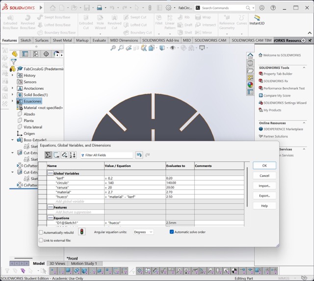
Equations in 3D modeling programs are very useful because they allow you to establish mathematical relationships and define variable values for the parts you design.
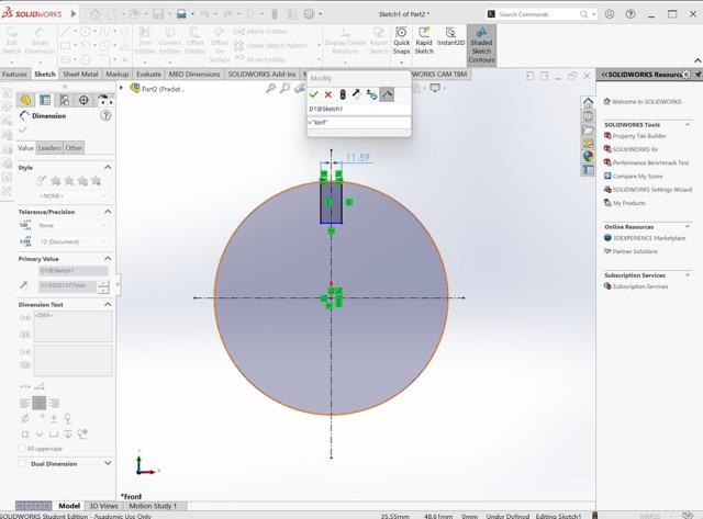
How to create equations?
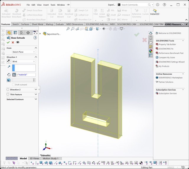
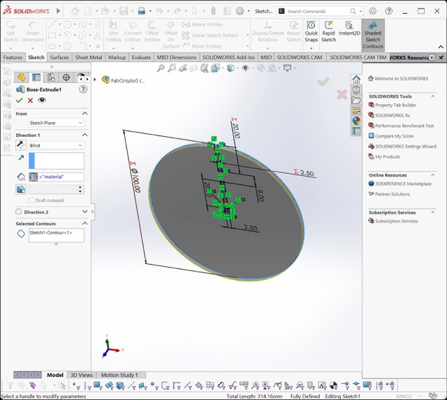
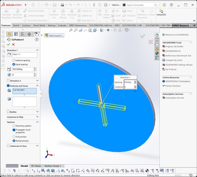
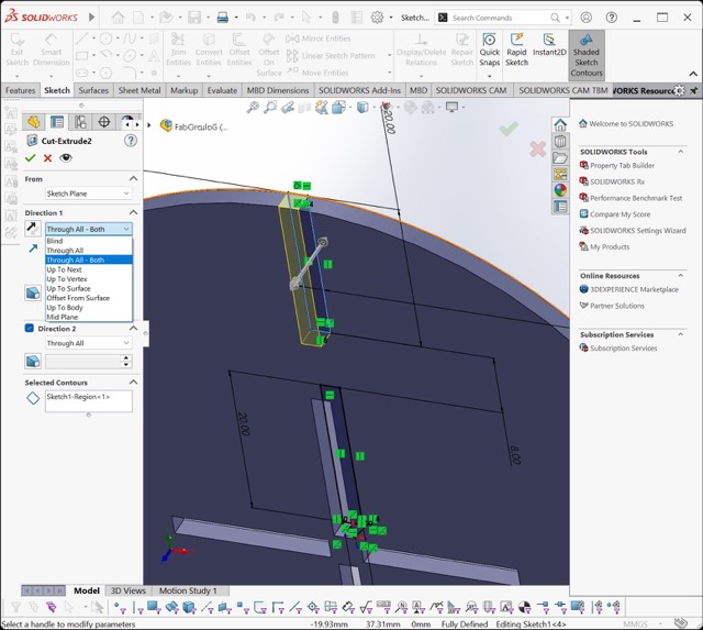
In SolidWorks, you can easily create global variables. You simply type ="Variable Name" while dimensioning a sketch. These variables can also be used when extruding or creating patterns. They are especially helpful for avoiding repetitive work and saving time.
Files for cutting
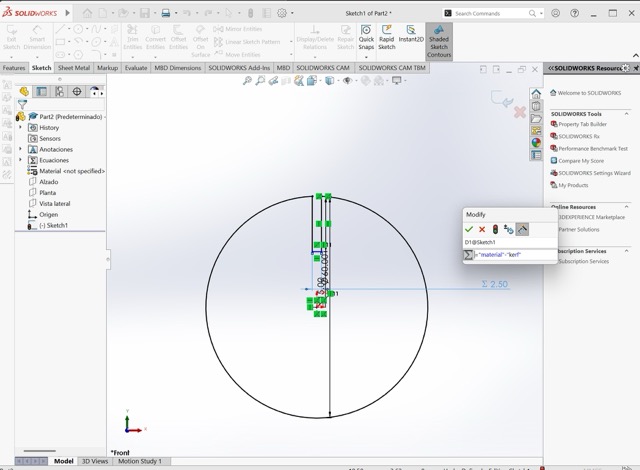
During class we got introduced to the term "kerf", which is the quantity of material that is removed during the cutting process
I first created small test pieces to verify whether the calculated kerf was correct. I designed two simple shapes to measure the fit for two different types of joints.
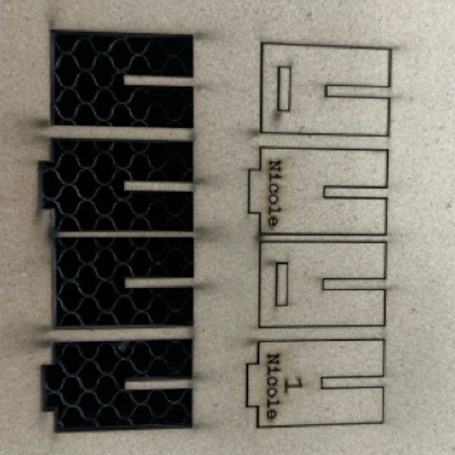
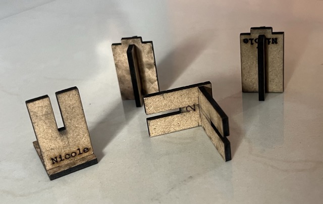
After testing, I concluded that although the group test resulted in a kerf of 0.14 mm, the pieces fit better when rounding it to 0.2 mm in the software
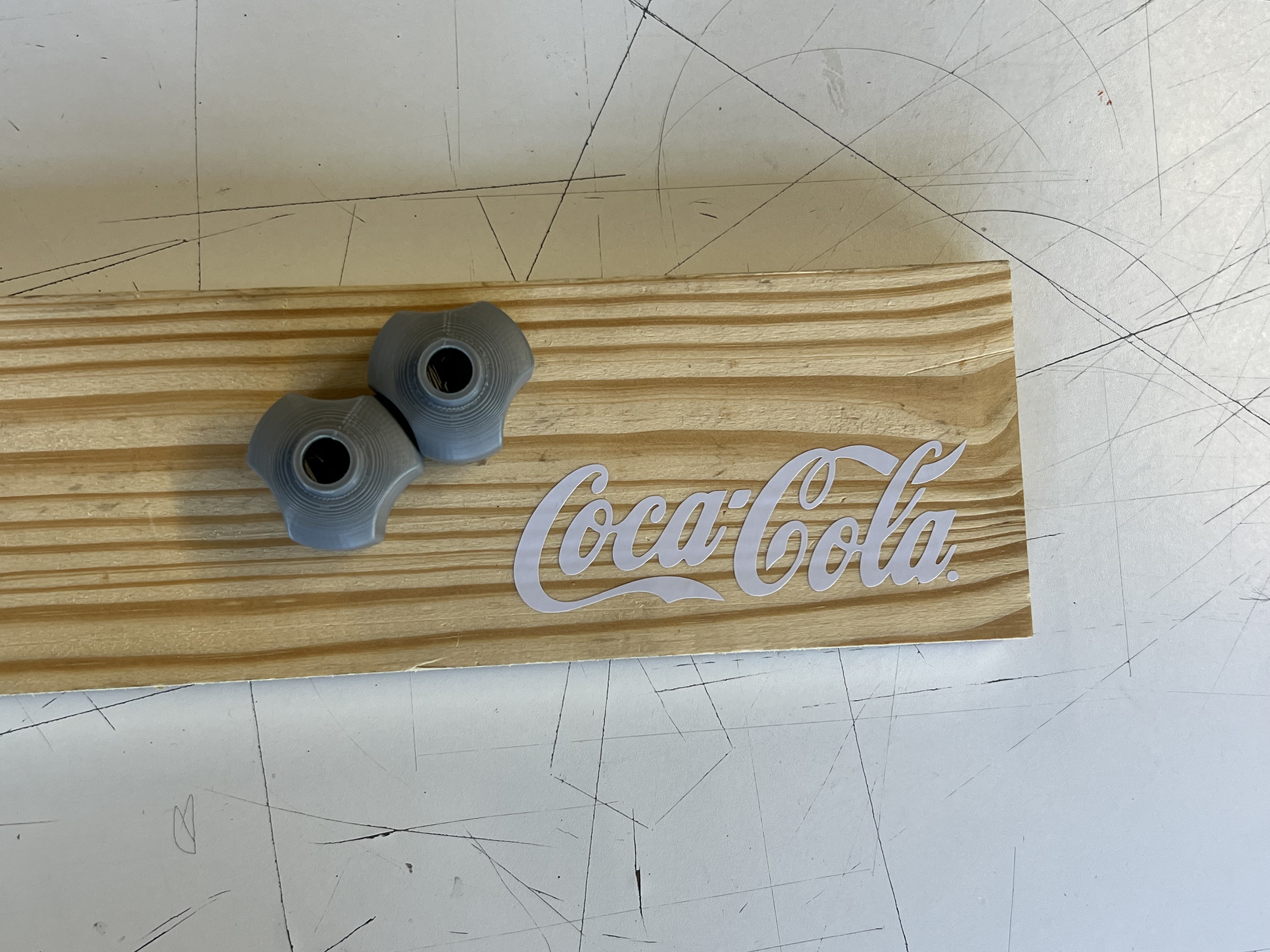
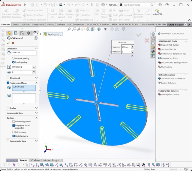
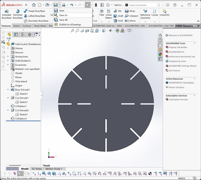
Using equations, I then scaled those same pieces to create the final, larger versions. I also designed an additional circular piece to have more shapes to experiment with in the kit.
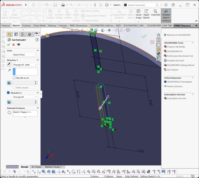
Here is the step-by-step process of how I made the pieces:
Laser cut pieces
Laser cut pieces
Laser cut pieces
Laser cut pieces
Laser cut pieces
Laser cut pieces
Laser cut pieces
Laser cut pieces
Laser cut pieces
Laser cut pieces
Laser cut pieces
Laser cut pieces
What I Learned in the Safety Training
It is important to monitor the laser cutter while it is operating in order to prevent accidents. Additionally, it is not advisable to stare directly at the laser for extended periods, as it may damage your eyesight.
Laser Cutting Process
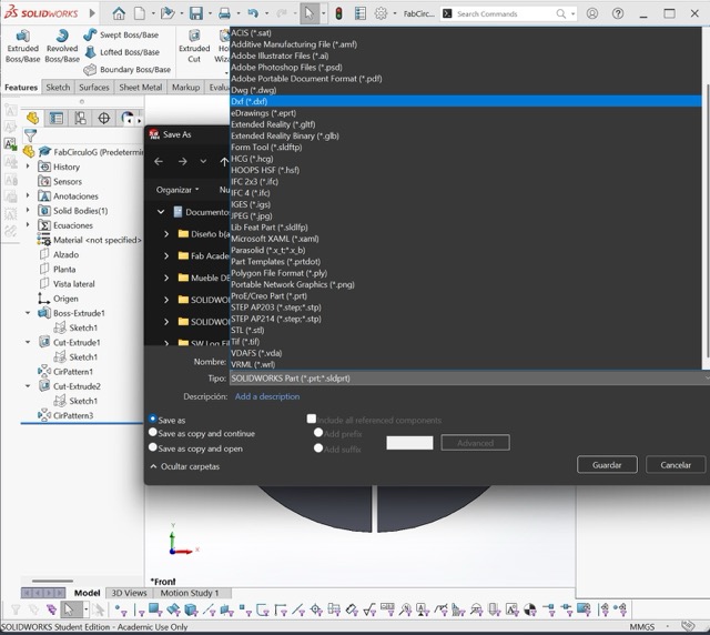
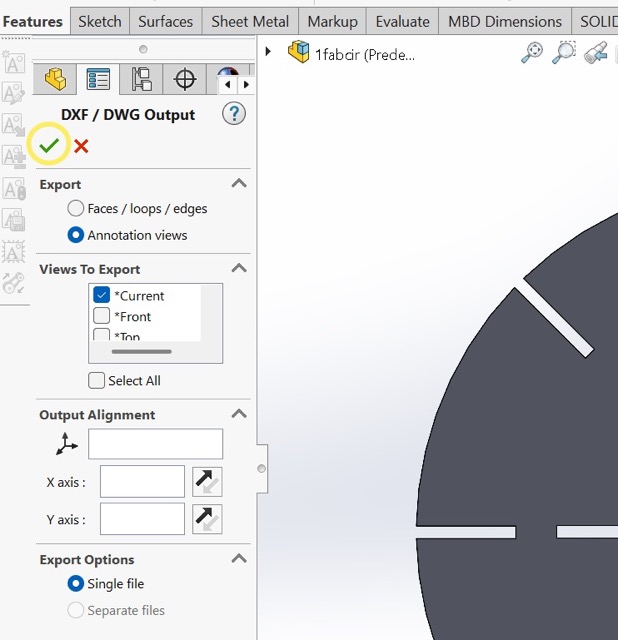
Our Fab Lab laser cutter works with DXF 2010 files.Initially, I exported the file as a DWG into AutoCAD and then converted it to DXF. Later, I tried exporting directly from SolidWorks, which also worked properly.
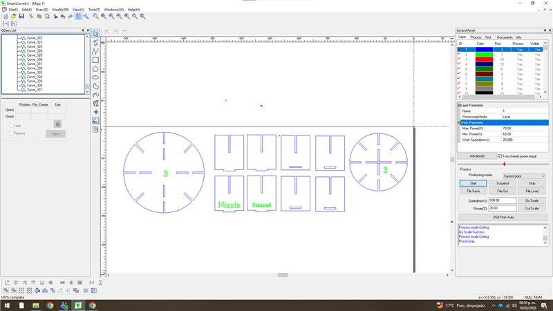
SmartCarve
I imported the files into SmartCarve, where I assigned different colors to each operation. This can be done in the control panel, where you can also define the cutting priority. It is important to set engraving operations before cutting.
Laser Parameters
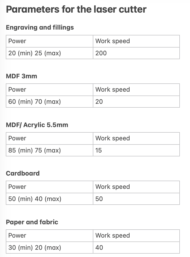
Since I had previously used the laser cutter, I already knew the appropriate parameters. In this case for cutting, I used a maximum power of 70, a minimum power of 60, and a work speed of 20. To engrave I used a maximum power of 25, a minimum power of 20, and a work speed of 200. Here are my laser parameters:
Laser Cutting Procedure
Before starting the cut, I used the “Go Scale” function to preview the laser path. After confirming that the path was correctly positioned over the material, I adjusted the head height using two 3 mm MDF pieces and began the cutting process.
Final result
Here are some of the configuarions that i was able to do with the kit:
Vinyl cutting
For the vinyl cutting I used a Cut Studio GS2-24 machine:
How to Use Cut Studio
- Load the vinyl roll into the machine.
- Turn on the machine and press “Enter.”
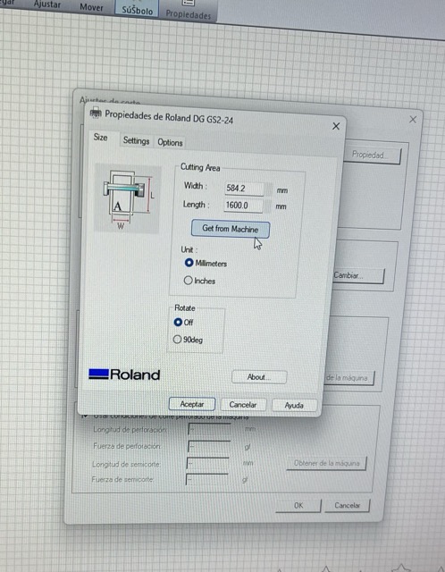
- Open the cutting settings in Cut studio and select “Change” in the material size section.
- Click “Get from Machine.”
- Go to the cut option and press “OK” to start the cut
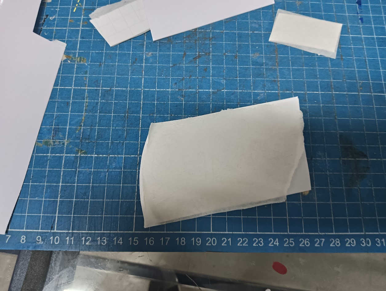
- Wait for the cut to finish and trim the used vinyl section with a cutter.
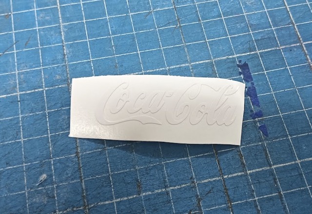
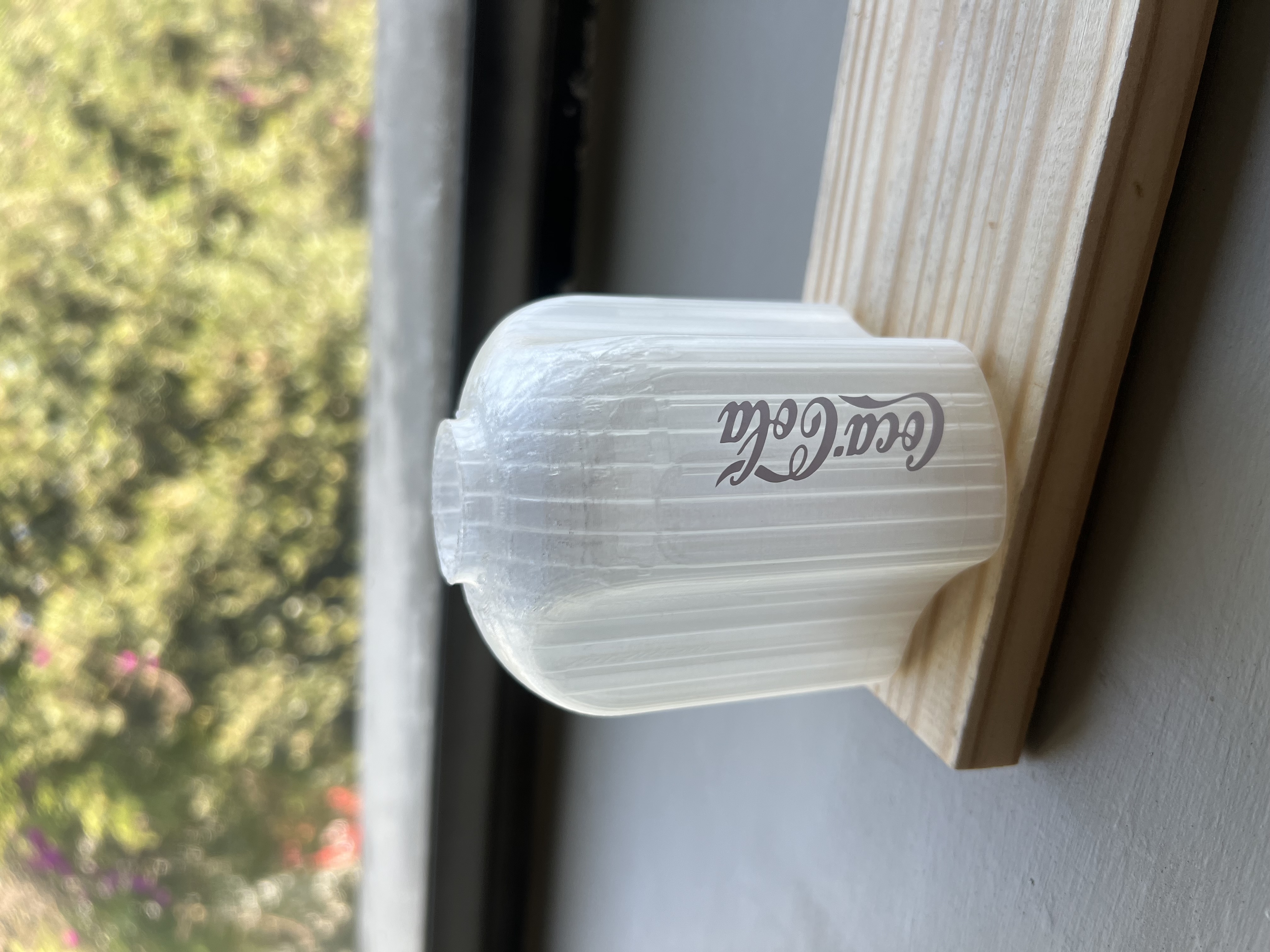
- Remove the parts of the vinyl you won't be using, it should look something like this:
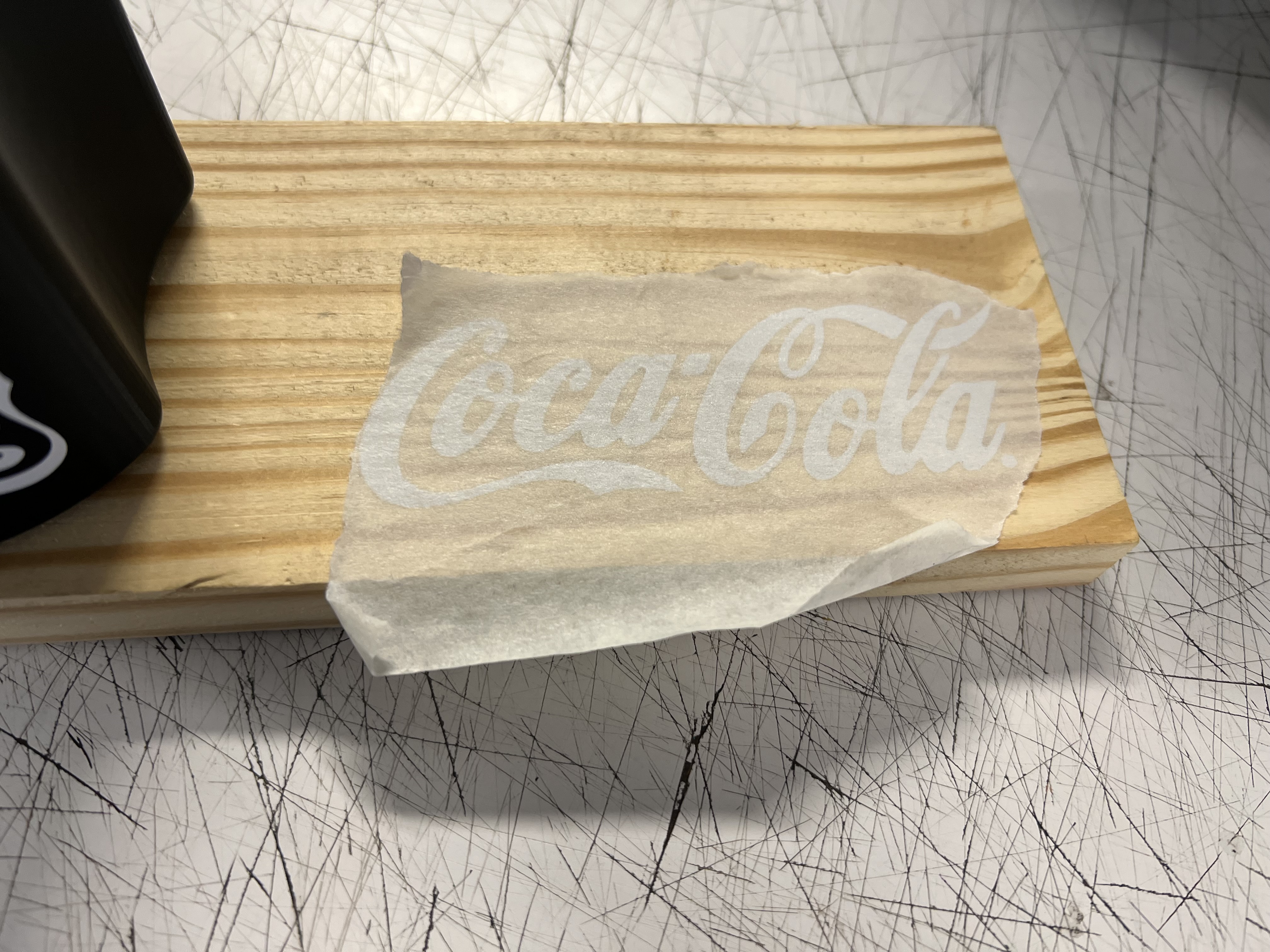
- Apply transfer tape over the design and ensure it adheres properly.
- Peel off the transfer tape with the vinyl attached and place it on the desired surface, pressing firmly to ensure adhesion.
- Carefully peel off the transfer tape so that you end up with something like this: