MISSION BRIEFING
This week I divided my workflow into two dimensions. Use the tabs below to switch between the 2D Vector work and the 3D Modeling process.
Modeling the Goal Sentinel in 2D & 3D Space
This week I divided my workflow into two dimensions. Use the tabs below to switch between the 2D Vector work and the 3D Modeling process.
Designing the visual identity and logos using vector and raster tools.
Before working, I selected two tools to compare their workflow for converting images to vectors.
Known for its powerful "Trace Bitmap" engine. Fast and automated.
Professional vector design tool, but lacks an auto-trace feature. Requires manual work.
Machines like laser cutters don't understand pixels; they need lines (vectors) to know where to cut. I used Inkscape to transform my normal images into vector files.
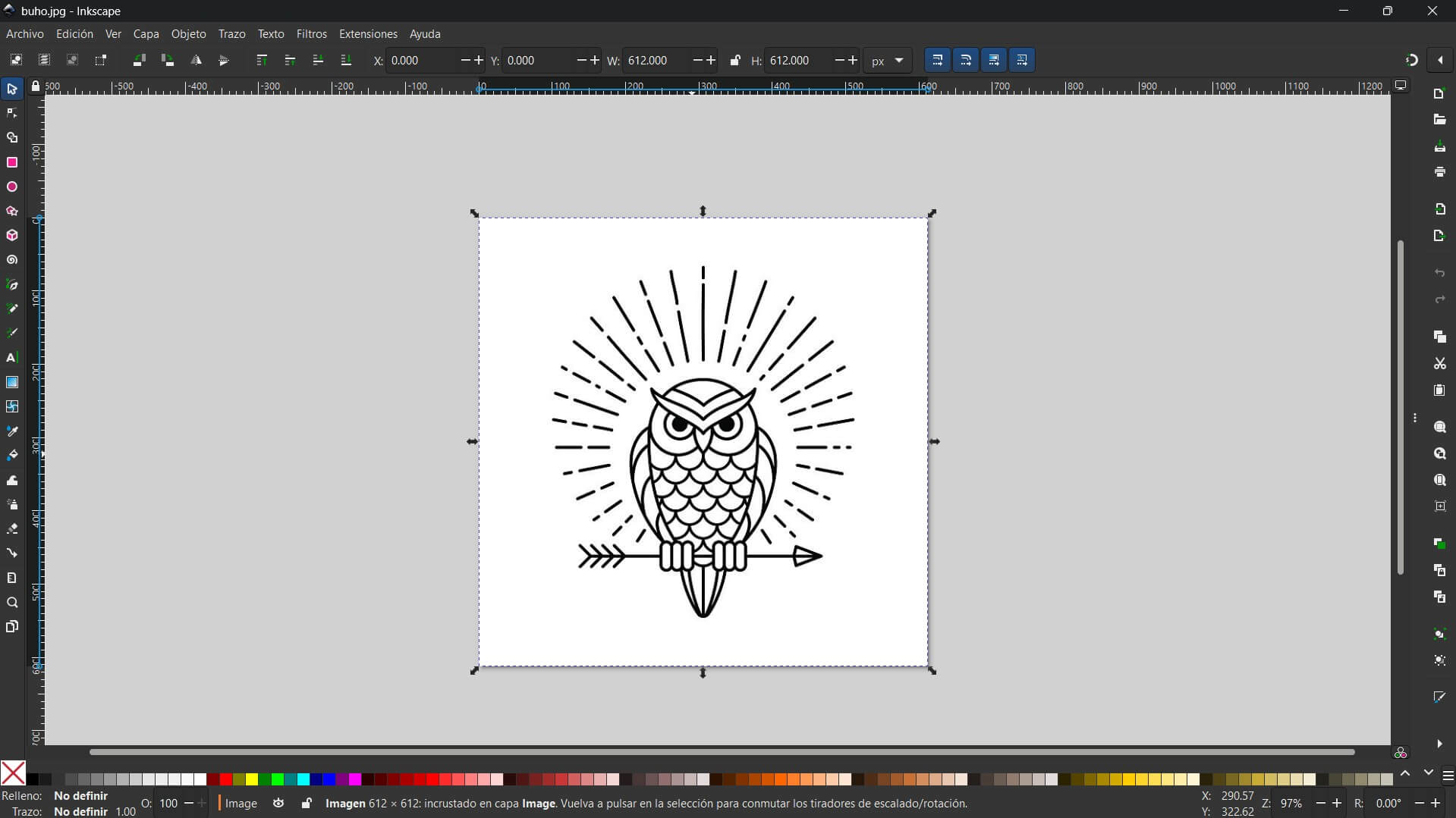
First, I imported the black and white image into Inkscape.
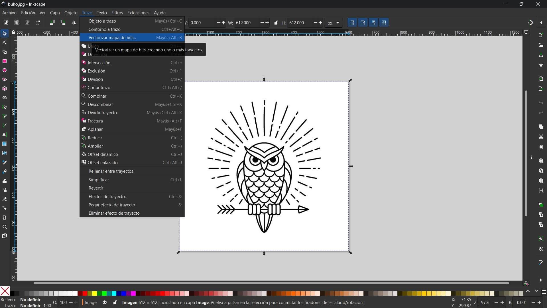
I went to the menu Path > Trace Bitmap. I chose the "Brightness Cutoff" mode, which is great for logos.
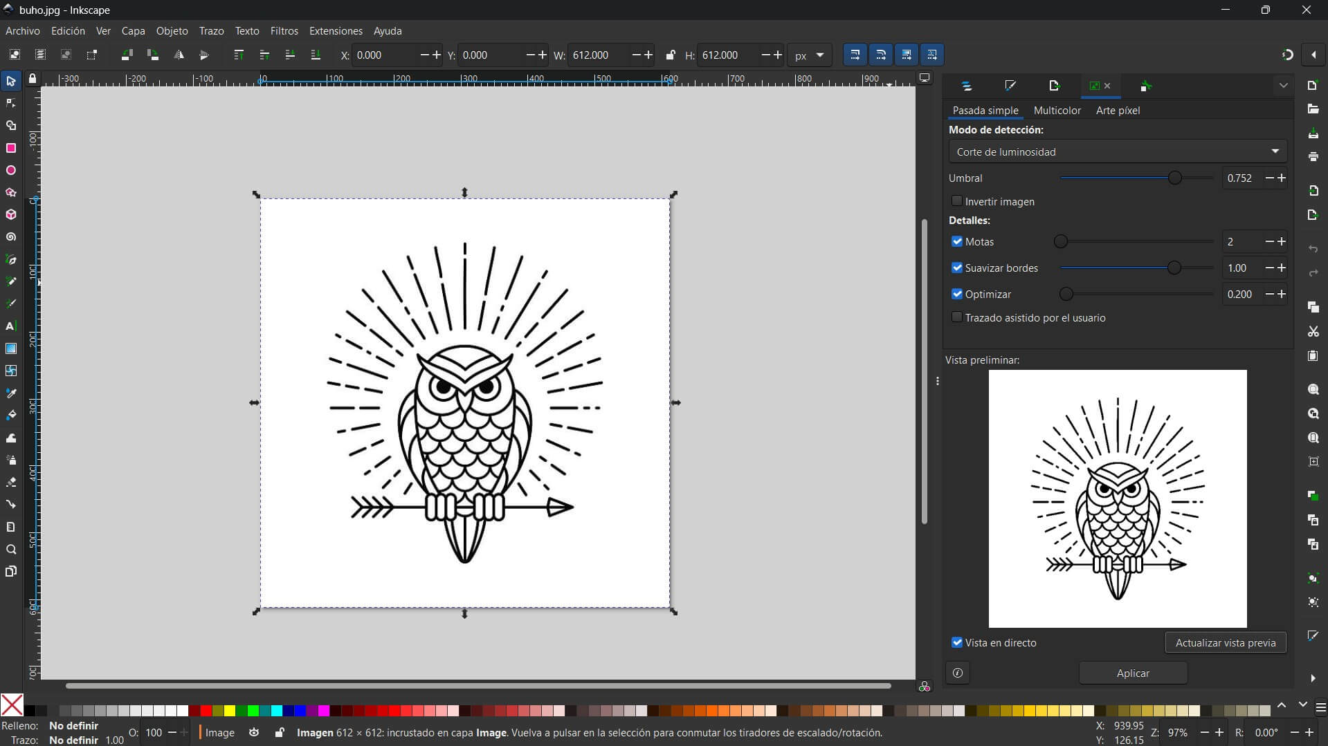
I adjusted the "Threshold" number (around 0.450) until the preview looked sharp and clear.
Here is the comparison. The original image (HERE) looks pixelated, but the new vector (NEXT IMAGE) is smooth.
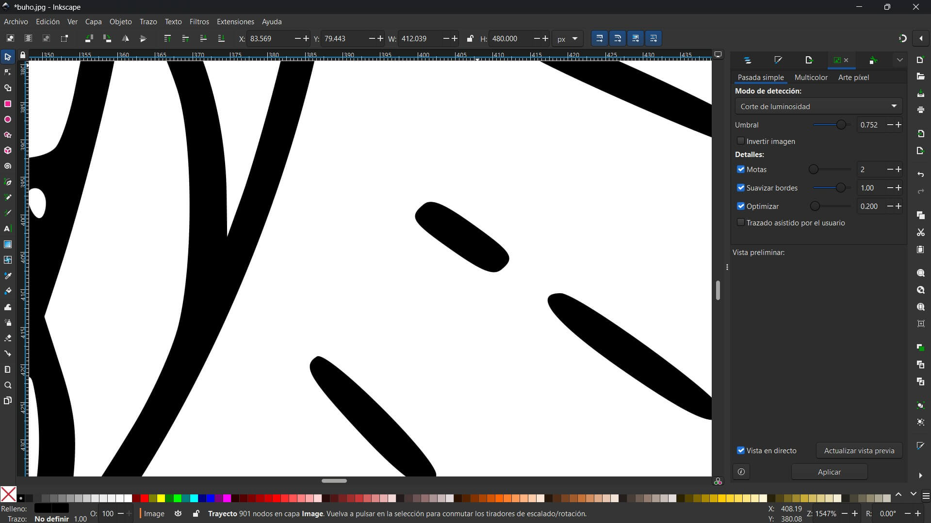
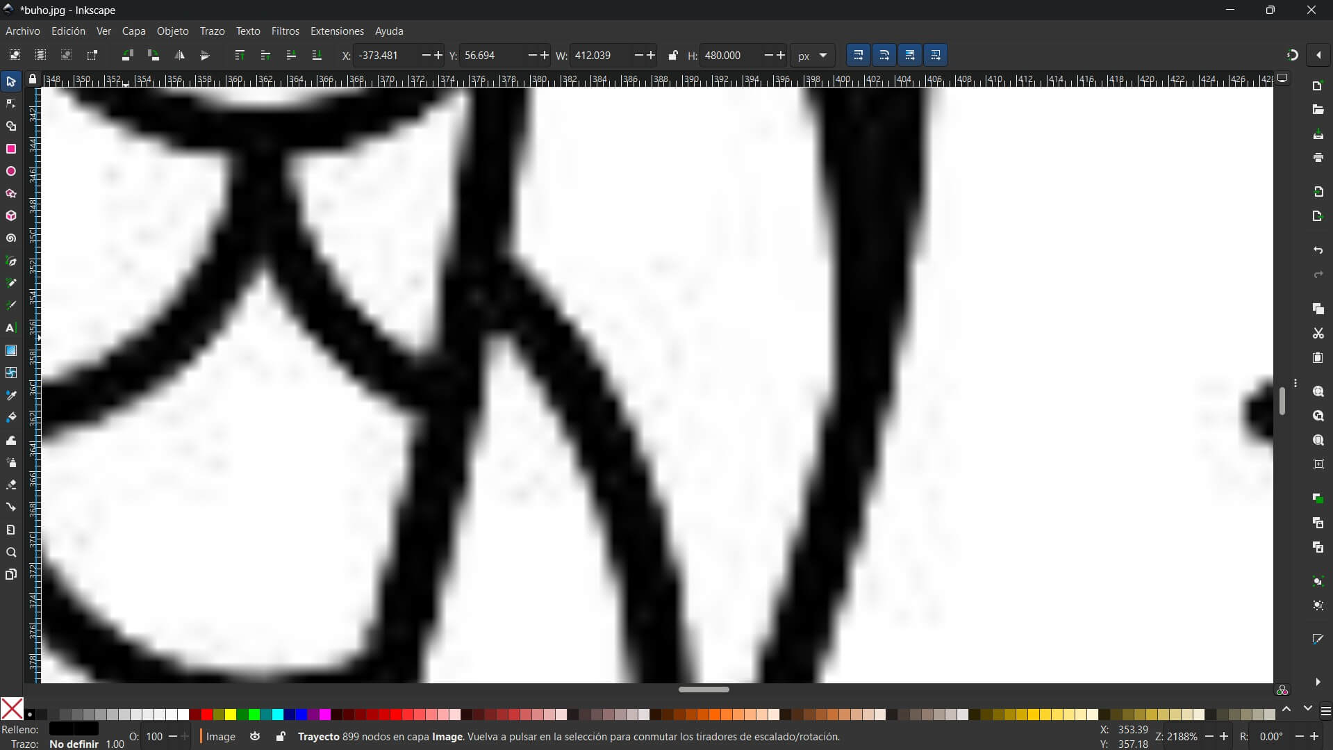
The result is a clean path. If I press F2 (the Node Tool), I can see the little points that define the shape. This is ready for cutting!
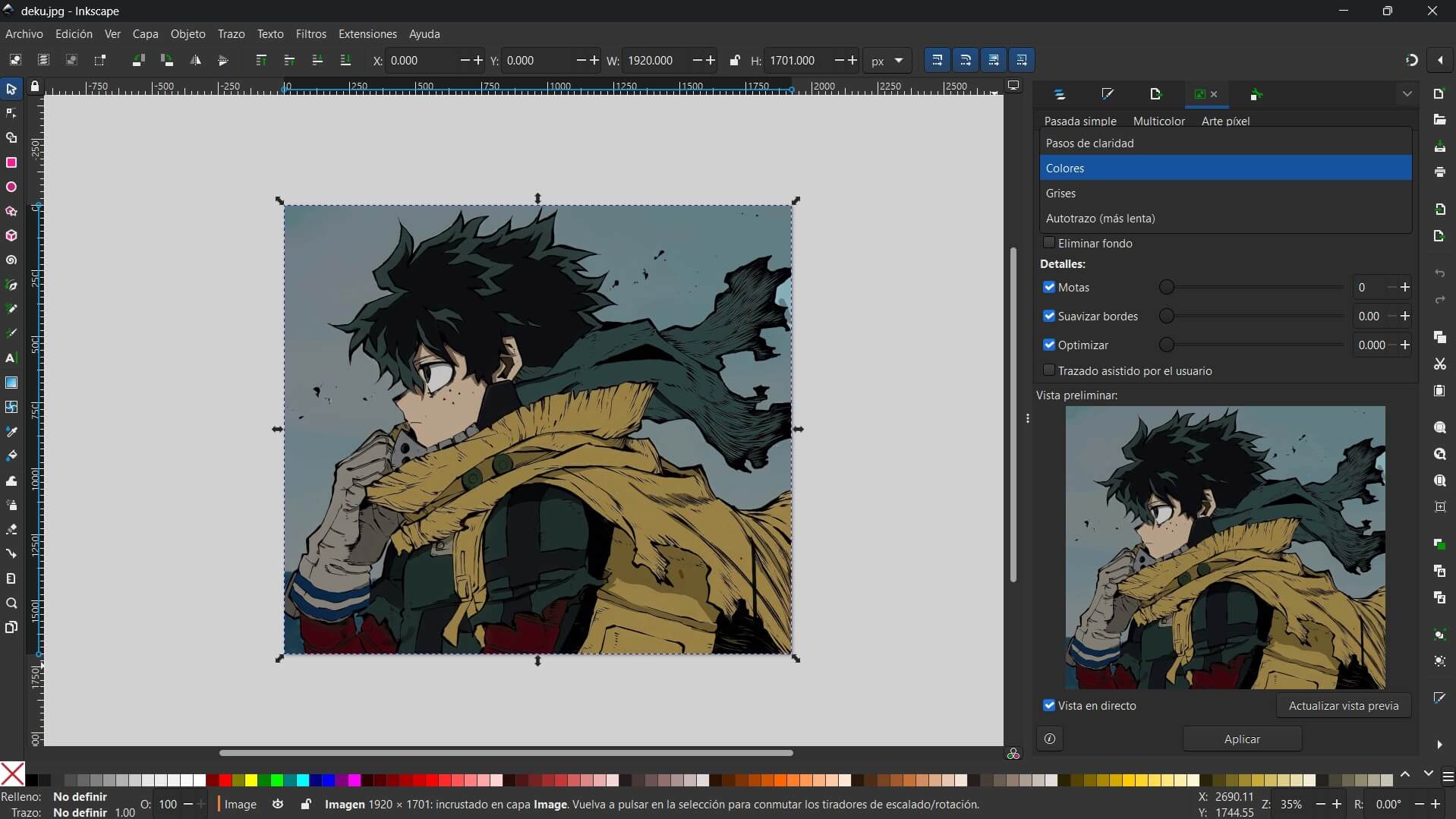
I imported a color picture. If I used the previous method, it would turn completely black, so I needed a different strategy.
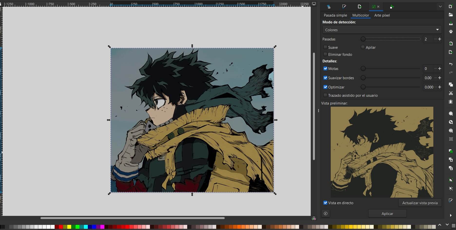
I selected the Multicolor tab and chose "Colors". I set the Scans to 12 to catch all the details and checked "Stack" to layer them correctly.
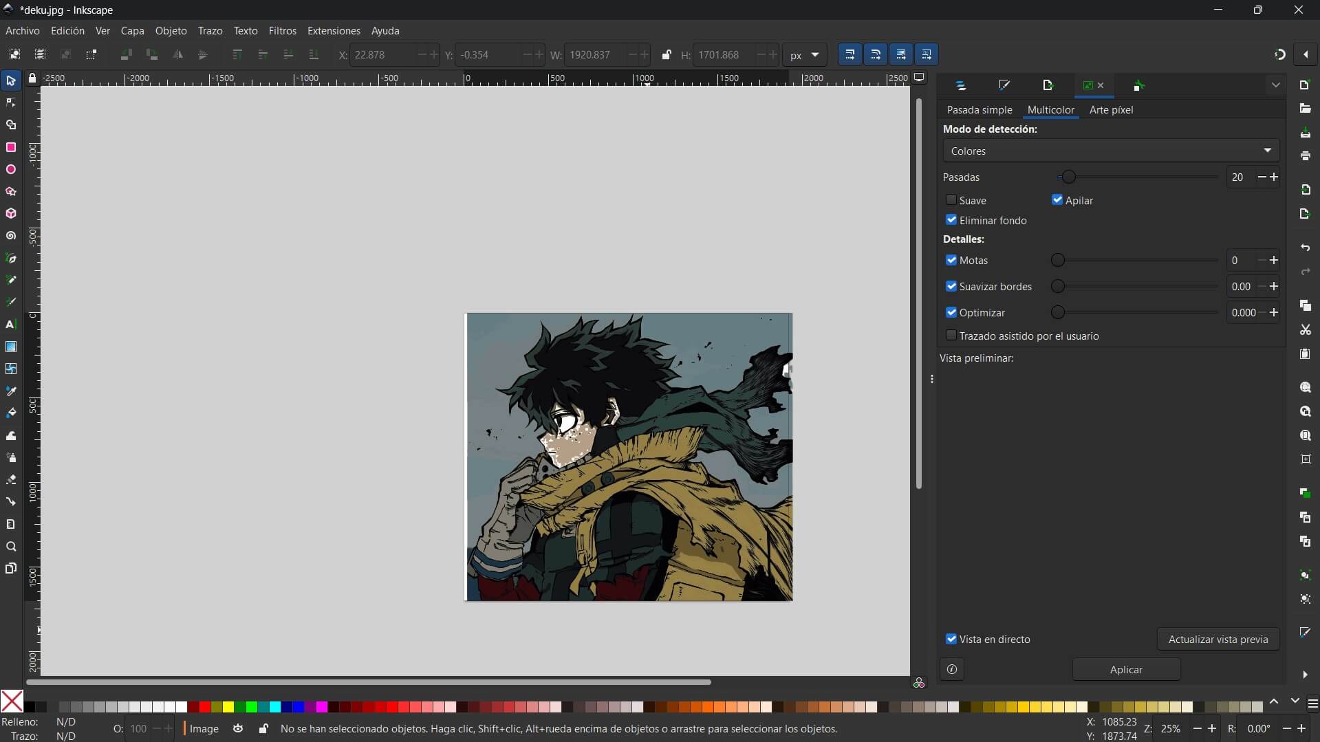
At first, the image looked like one single block. I had to click Object > Ungroup to separate the color layers.
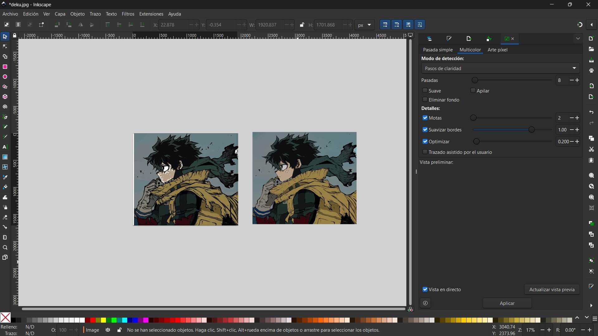
Success! Now the image is made of different vector layers stacked on top of each other, keeping the original colors.
Unlike Inkscape, Affinity Designer does not have an "Auto-Trace" feature. This forced me to use the Pen Tool to manually trace the logo. This method is slower but produces the cleanest possible vectors with minimal nodes.
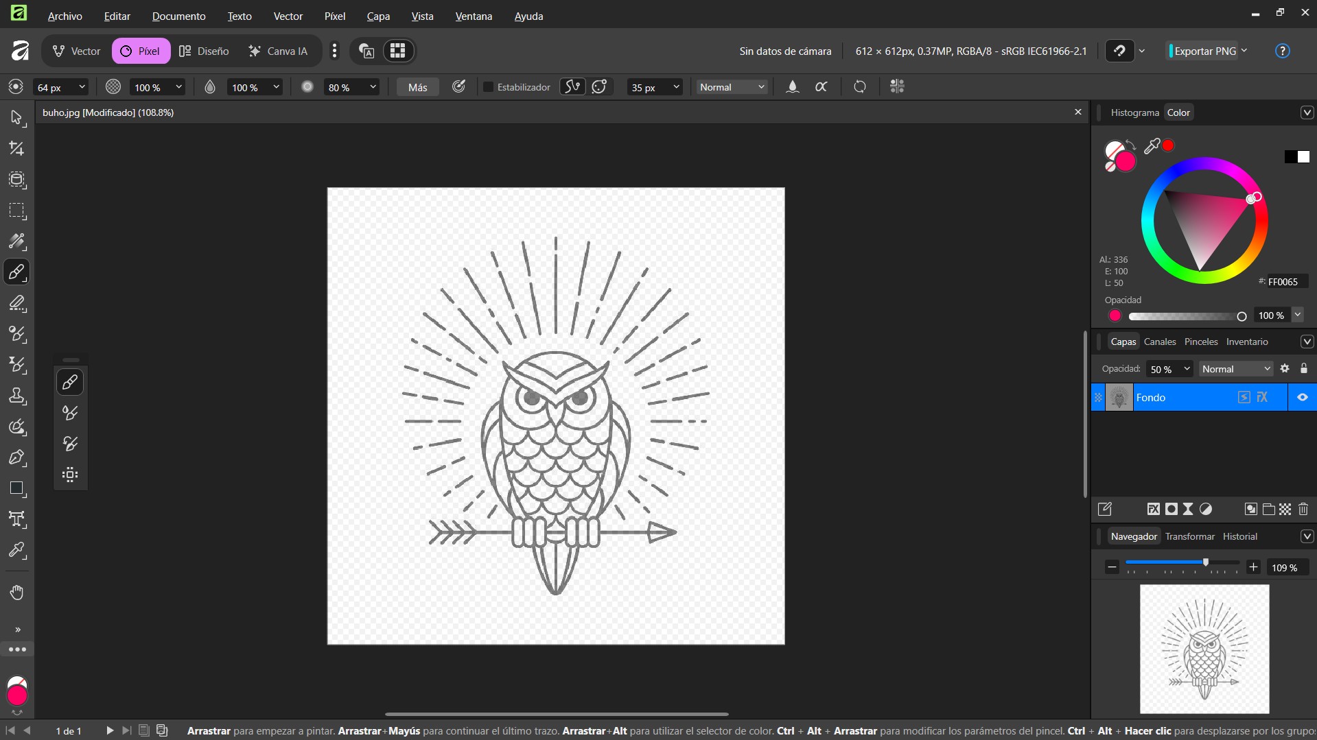
I placed the raster image on the artboard and lowered the Layer Opacity to 50%. I also locked the layer to use it as a tracing reference.
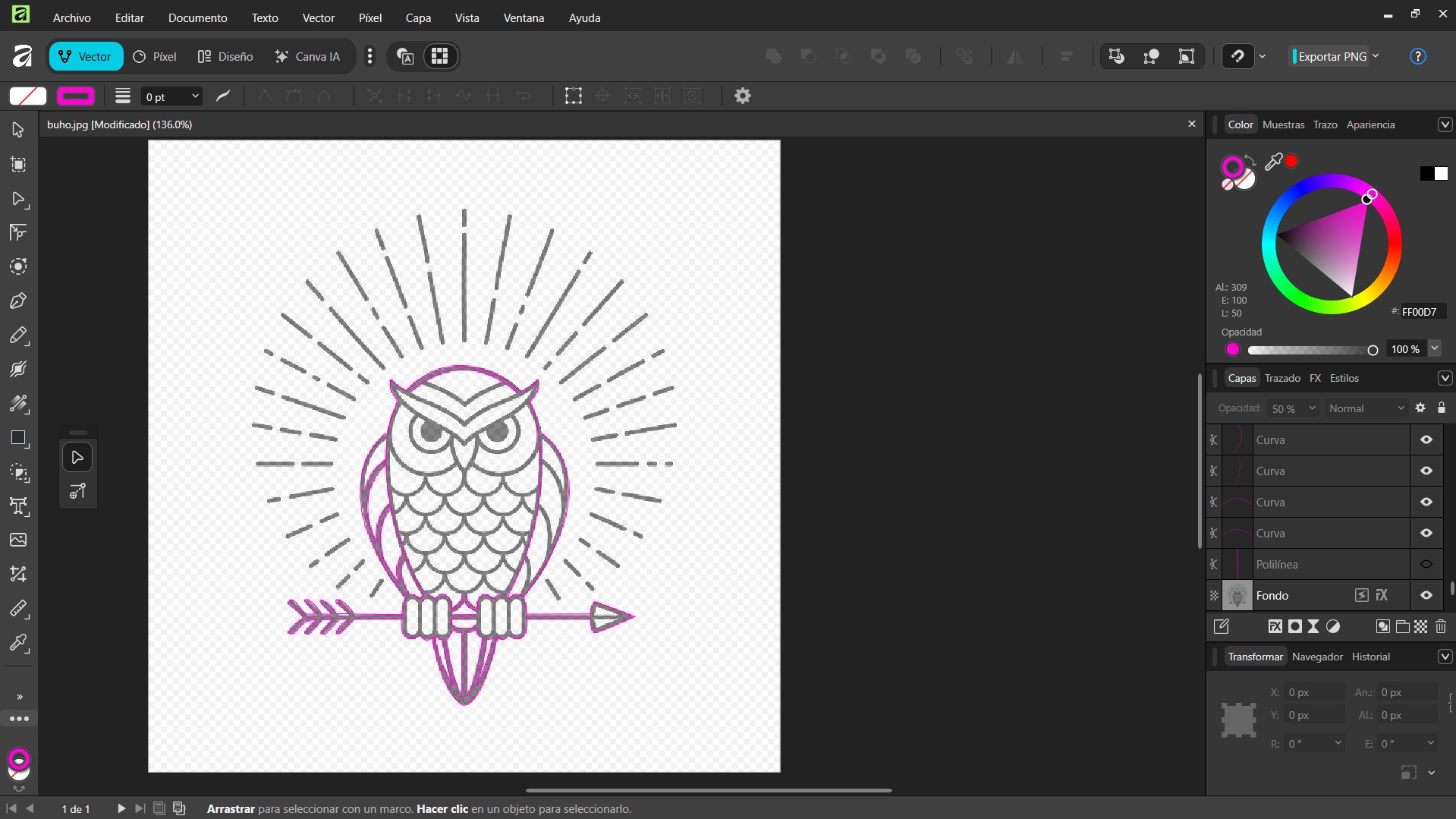
Using the Pen Tool (P), I manually drew the path node by node. I set the fill to "None" and the stroke to a bright pink to see my lines clearly.
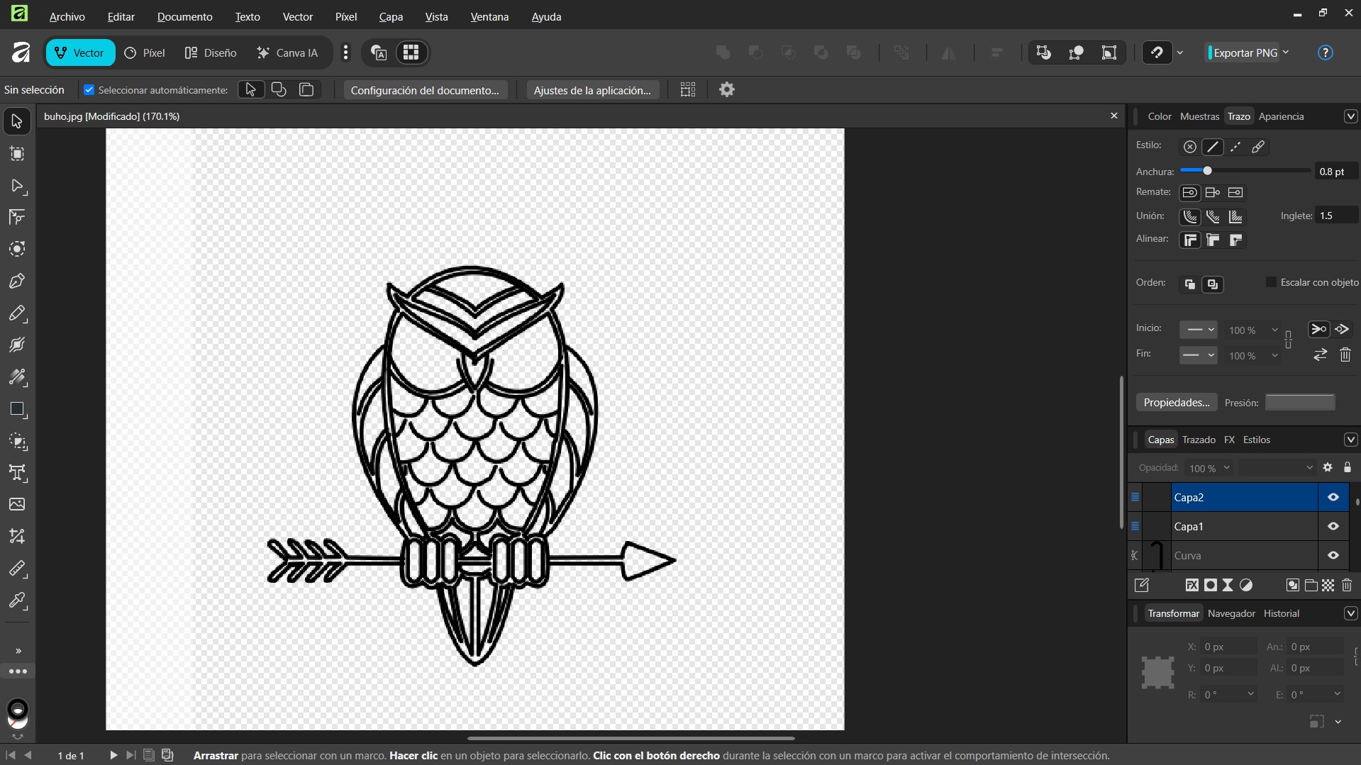
The Payoff: After completing the trace, I changed the stroke to black and increased the width to 0.8pt. The result is a sharp, clean line-art logo with perfect geometry, far cleaner than any auto-trace could achieve.
After testing both software packages to vectorize similar images, I have a very clear winner for my workflow.
Honestly, I did not enjoy the experience of tracing images here. The lack of an "Auto-Trace" feature is a huge disadvantage.
Inkscape is simply faster and smarter. The "Trace Bitmap" engine is a lifesaver when you need to digitize a sketch or a logo quickly.
My documentation wouldn't be complete without optimizing the video assets. High-quality video kills website loading times. I decided to use FFmpeg via the command line to crush the file size, but the terminal fought back. Here is the log of the battle:
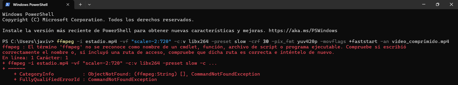
The Problem: As seen in the red text, Windows had no idea what "ffmpeg" was. The executable wasn't in the system PATH.
The Fix: I had to install FFmpeg properly (using winget or setting environment variables) so the terminal could find the program.
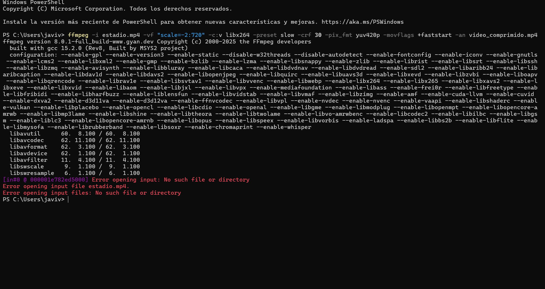
The Problem: FFmpeg was now running (yay!), but it couldn't find the video. The screenshot shows a error: the terminal was looking in the wrong folder.
The Fix: I corrected the filename and used the full path to the Downloads folder ("C:\Users\javiv\Downloads...").
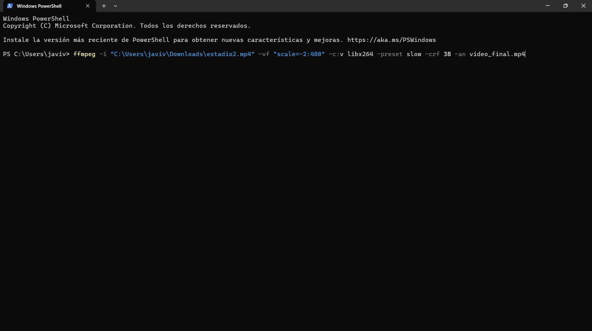
The Problem: A classic mistake. I copied the command from a tutorial but accidentally included the terminal prompt (`PS C:\Users\javiv>`) at the beginning. PowerShell got confused by the extra "PS".
The Fix: I cleared the line and pasted only the clean command starting with ffmpeg.
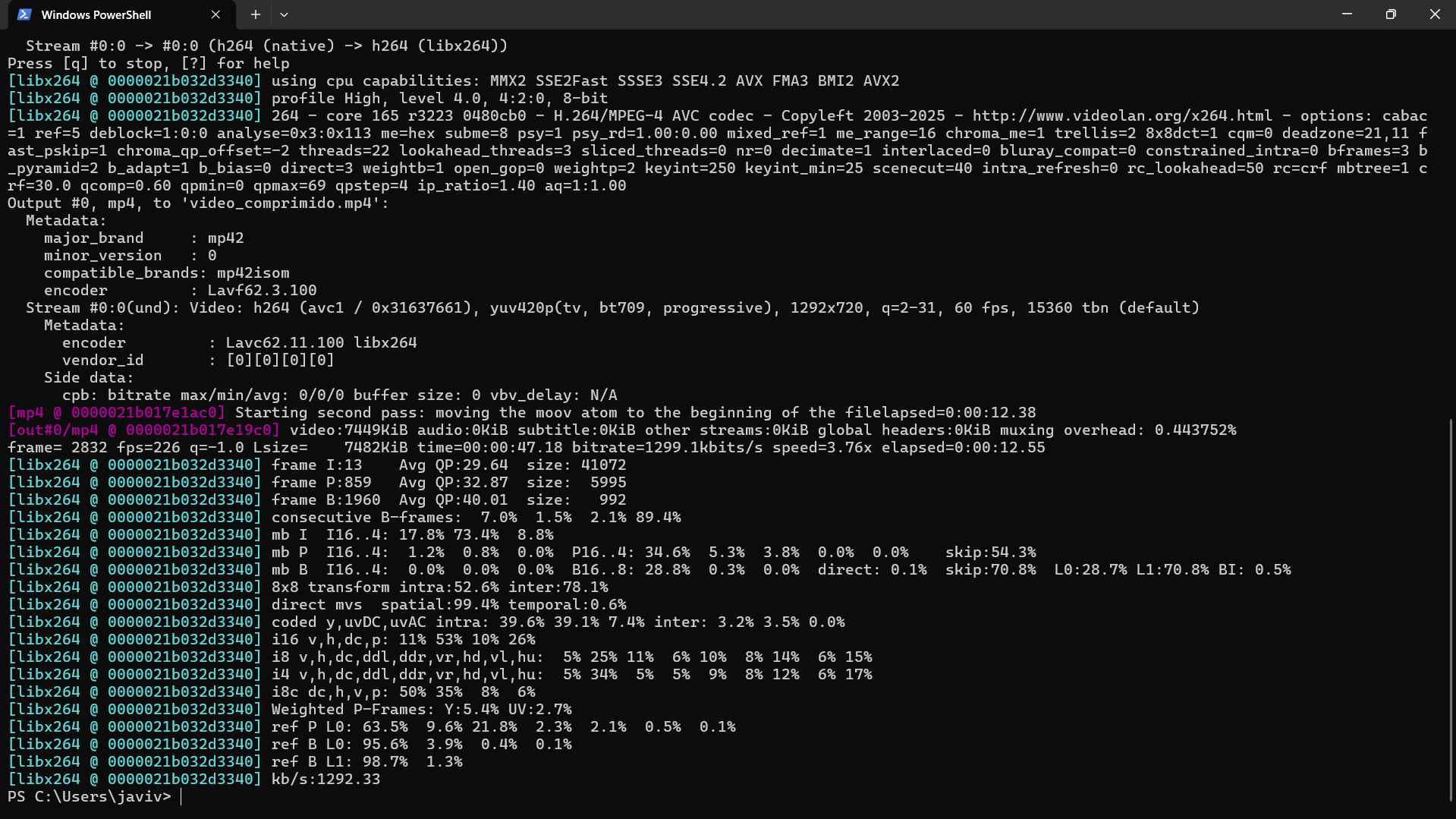
The Process: Finally! This wall of scrolling text means it's working. The terminal shows the compression speed (fps), the current bitrate, and time remaining. I used aggressive settings for maximum compression.

The Result: The file explorer proves the victory. The original estadio2.mp4 was a massive **56,897 KB** (about 57MB). The new `video_final.mp4` is just **2,892 KB** (about 3MB). That's a **90% reduction** in size!
Optimized (Fast load)
Download the video compression tool at the bottom of the page
Creating the physical parts of the Goal Sentinel in the digital world.
Before diving into the detailed process, I put both contenders to the test. Here is my analysis:
THE DIGITAL WORKBENCH: READY TO MODEL
My preferred tool. Powerful, stable, and works offline. Great for complex assemblies.
Cloud-based and collaborative. Amazing for working on any computer, but depends on internet.
I did the same exact shape in both programs to compare how I feel while working with each. Here are the screenshots and my observations:
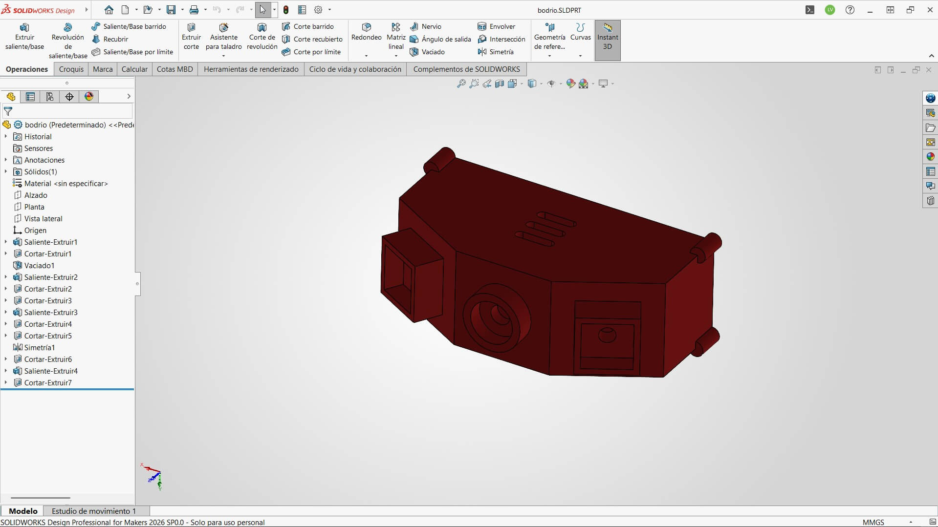
SOLIDWORKS INTERFACE
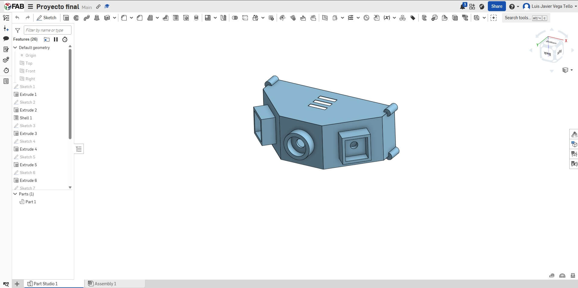
ONSHAPE INTERFACE
After testing both, I decided to stick with SolidWorks as my main software. While Onshape is great for quick access and intuitive, I found SolidWorks to be more robust for my needs.
The feature tree feels more organized to me, and since I sometimes work in places with unstable internet, having an offline tool is non-negotiable. Also, the assembly features in SolidWorks gave me more control over the mechanical mates for the clamp mechanism.
The step-by-step construction of the Enclosure.
Here is the step-by-step visual log of how I designed the piece, from the first sketch to the final render.
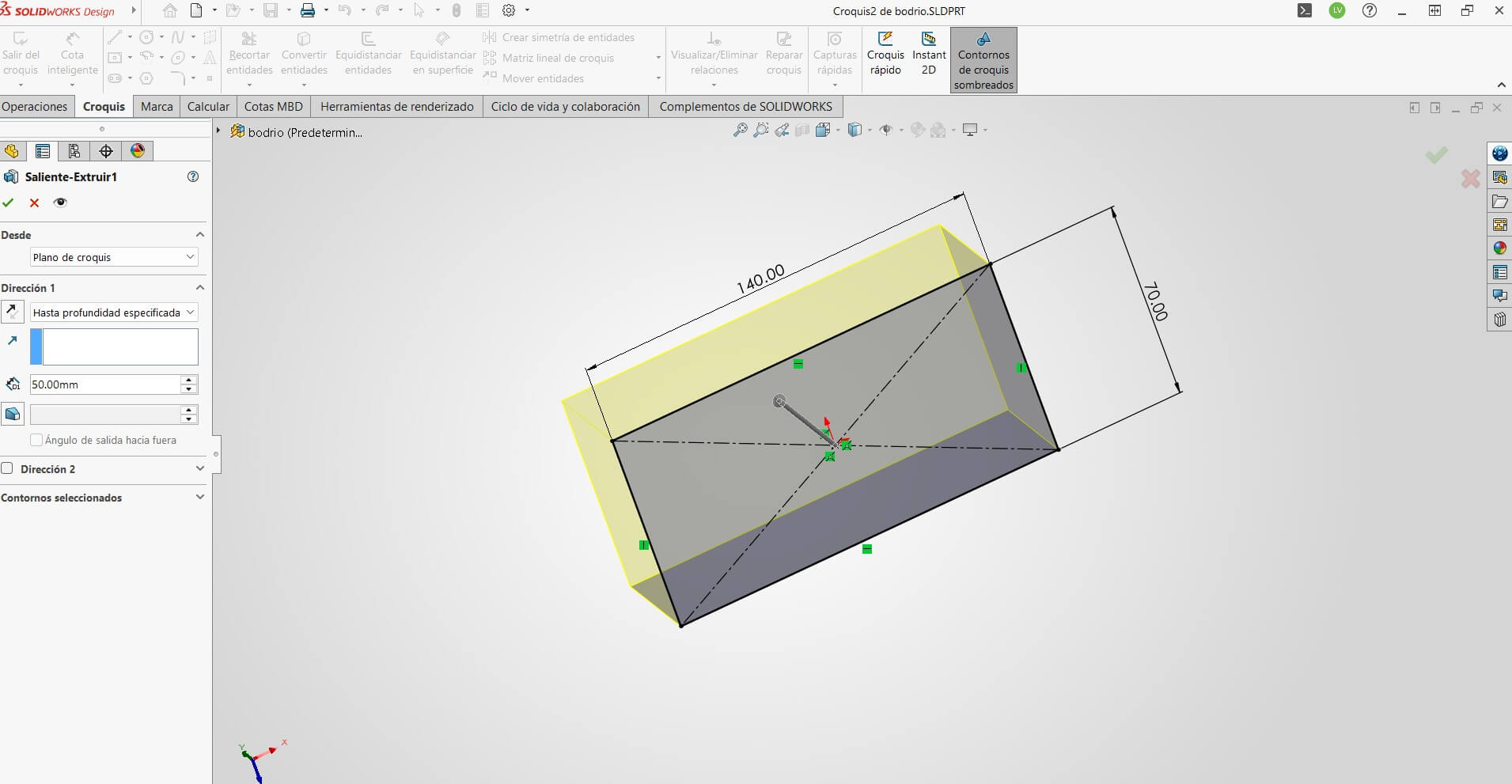
Initializing the base sketch with a center rectangle and extruding it to create the main volume of the device.
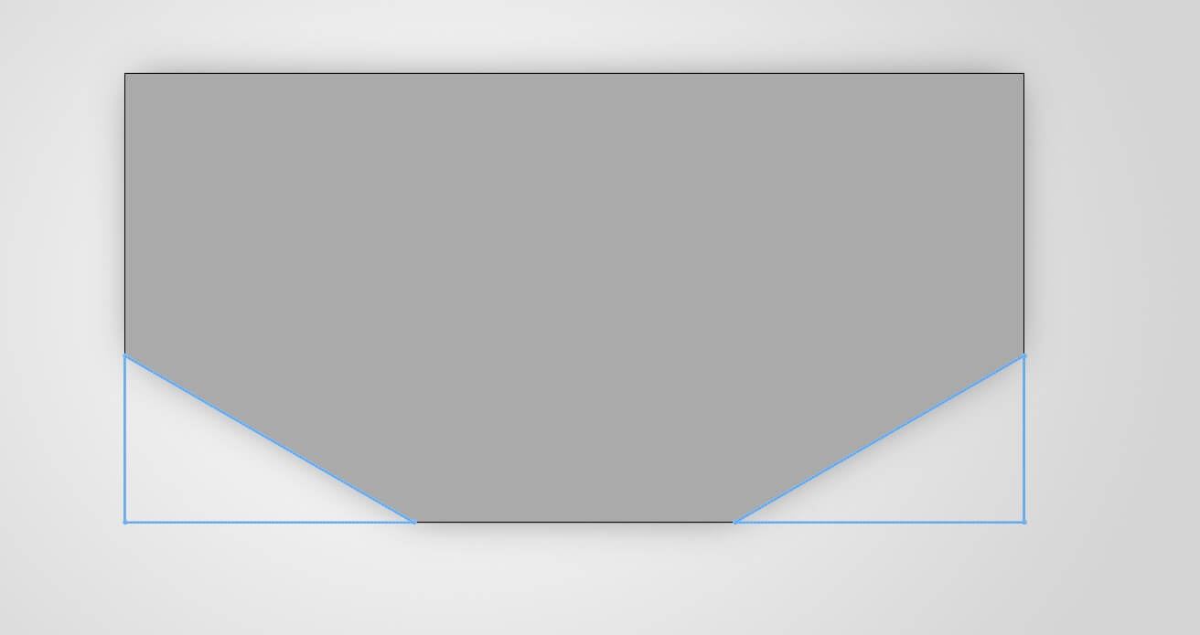
Creating Extruded Cuts to shape the profile and remove unnecessary material.
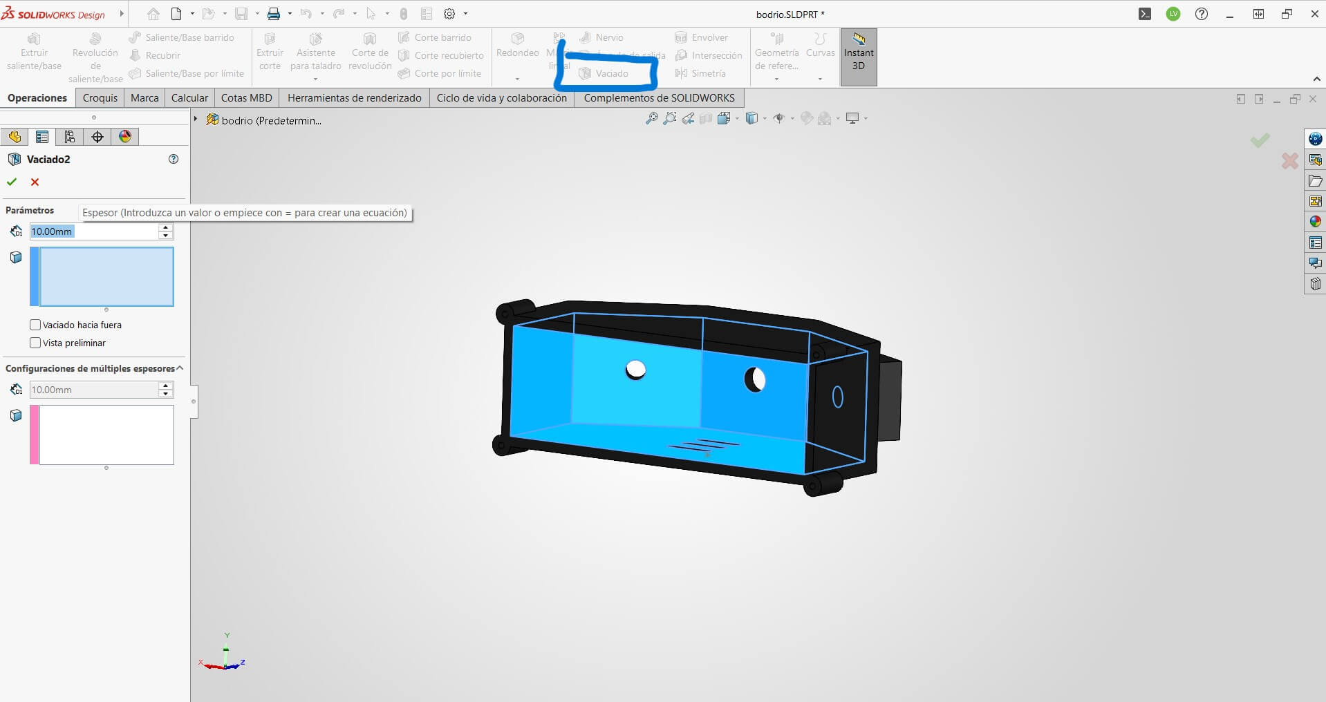
I applied the Shell Feature to hollow out the interior of the piece with a uniform wall thickness.
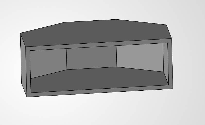
Visual result after the shell operation. The enclosure is now ready for internal components.
Drafting the sketch for the specific camera module mount.
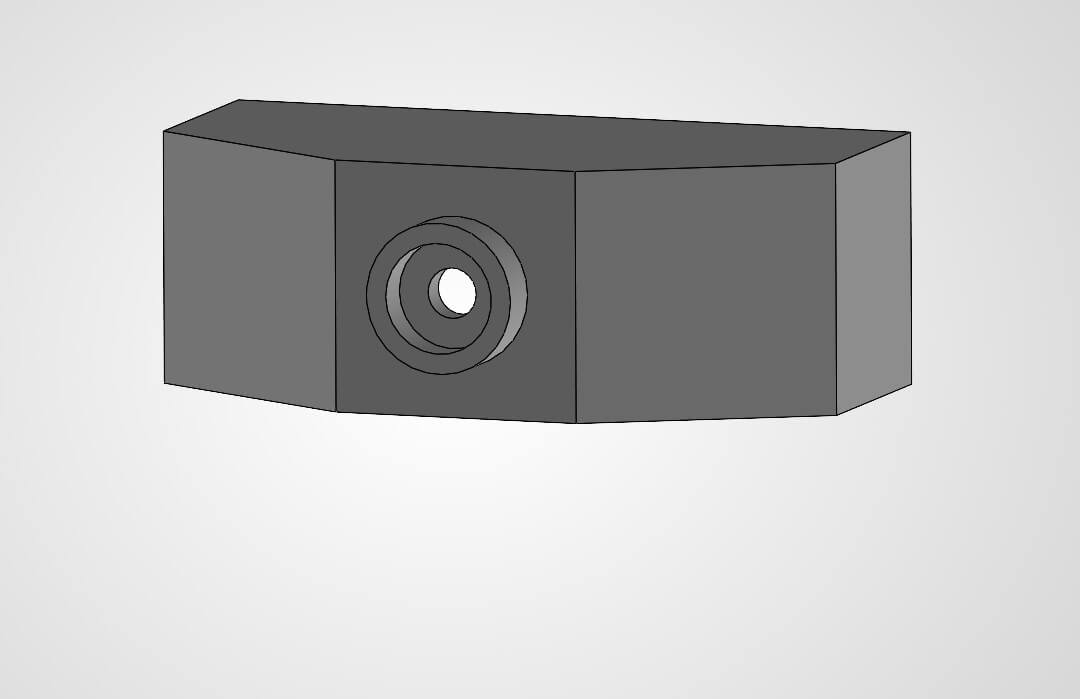
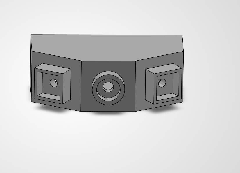
Extruding the camera housing to protect the lens.
Defining the geometry for the sensor compartments on the side.
Cutting the enclosure to create precise openings for the sensors.
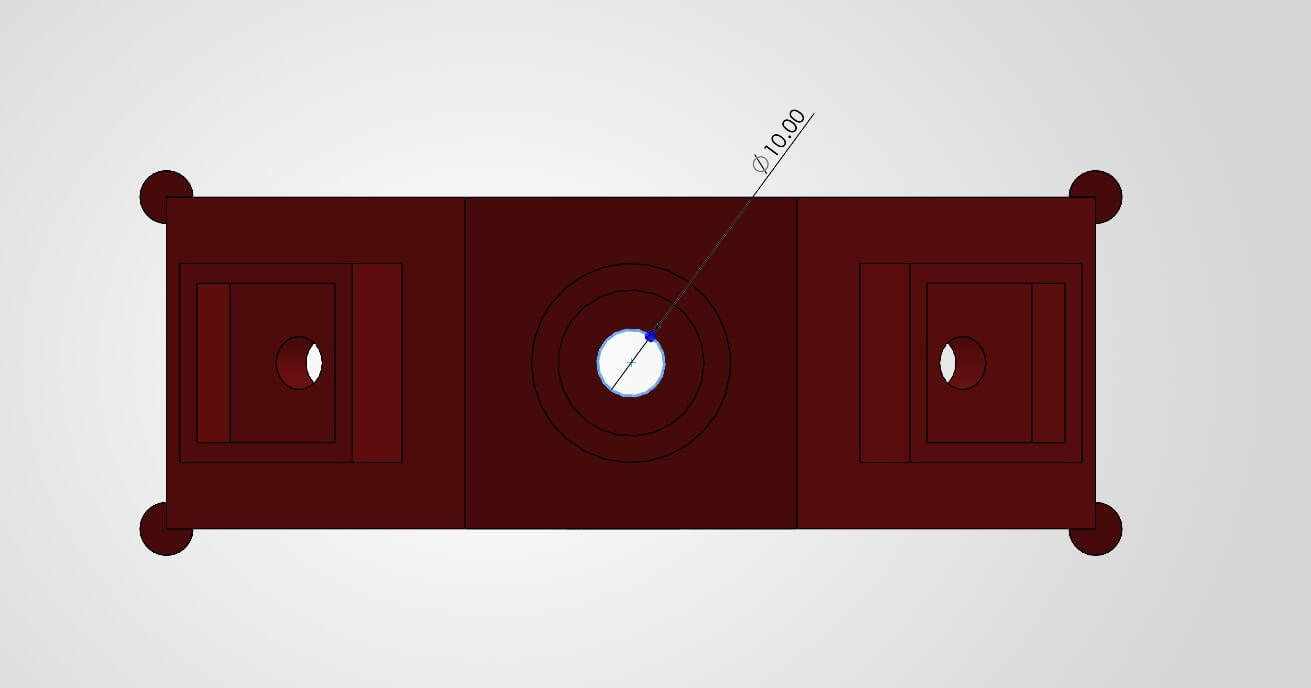
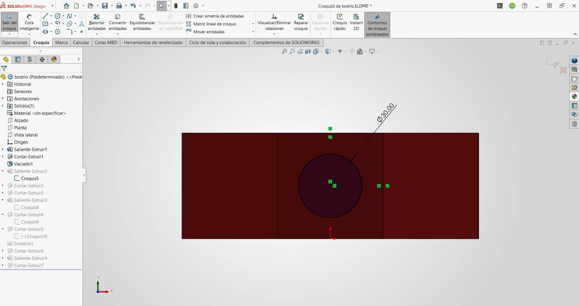
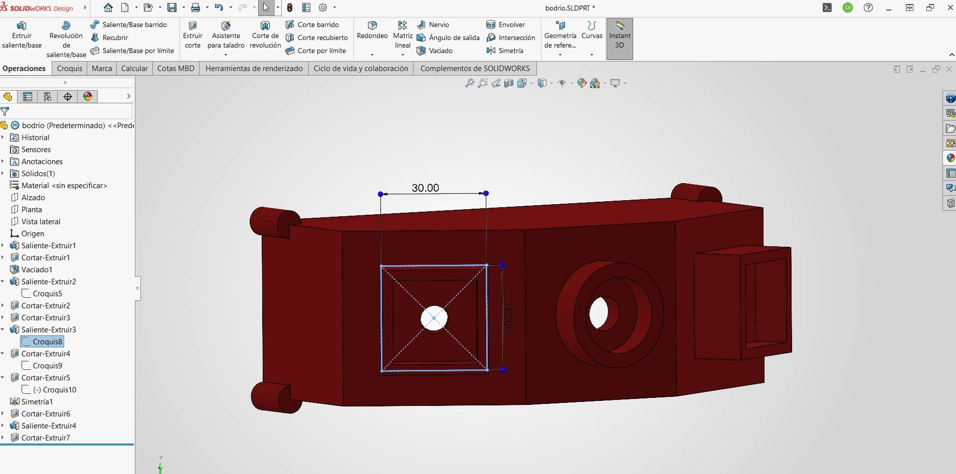
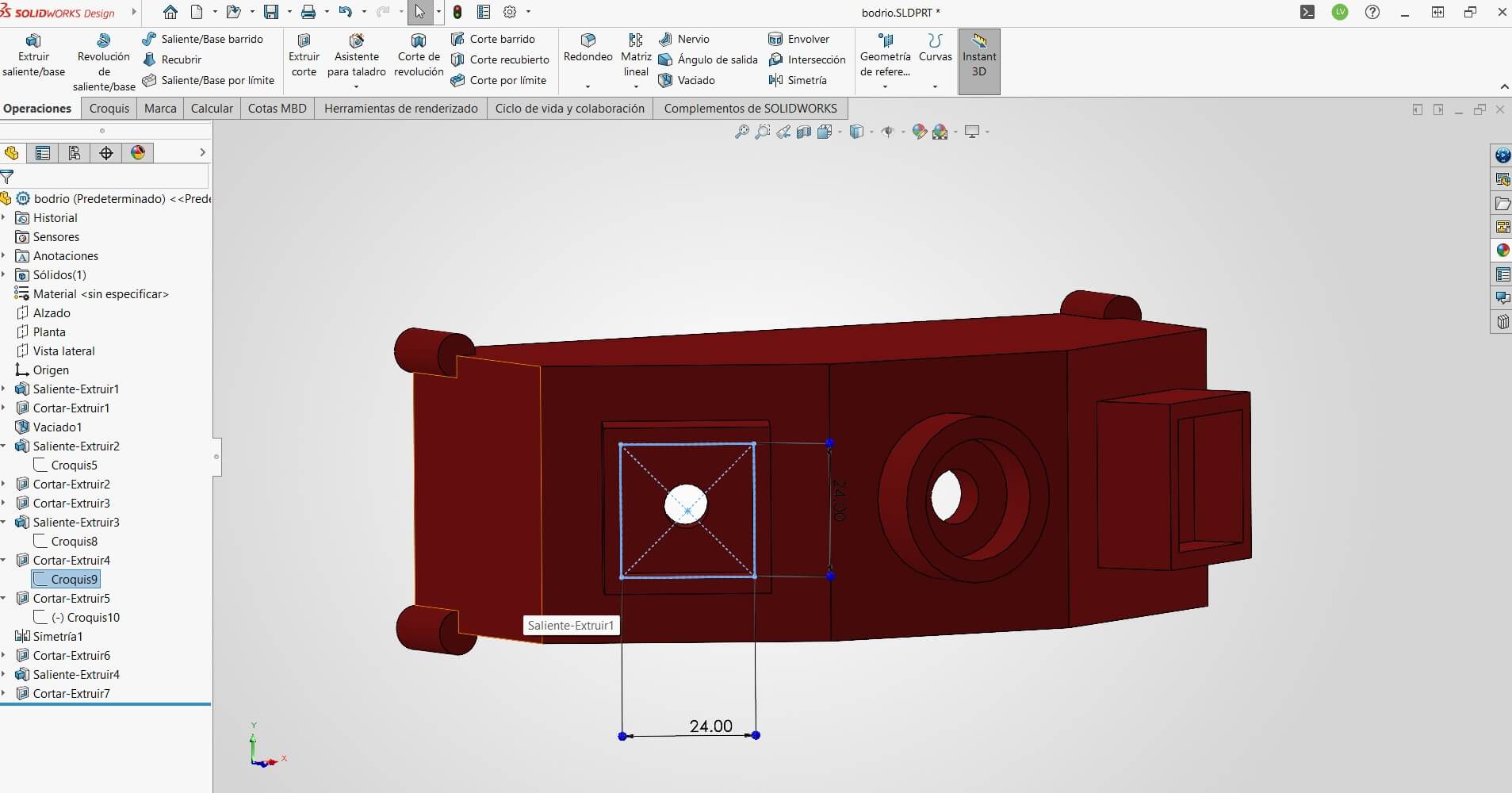
Drilling mounting holes using the Circle and Cut Extrude tools.
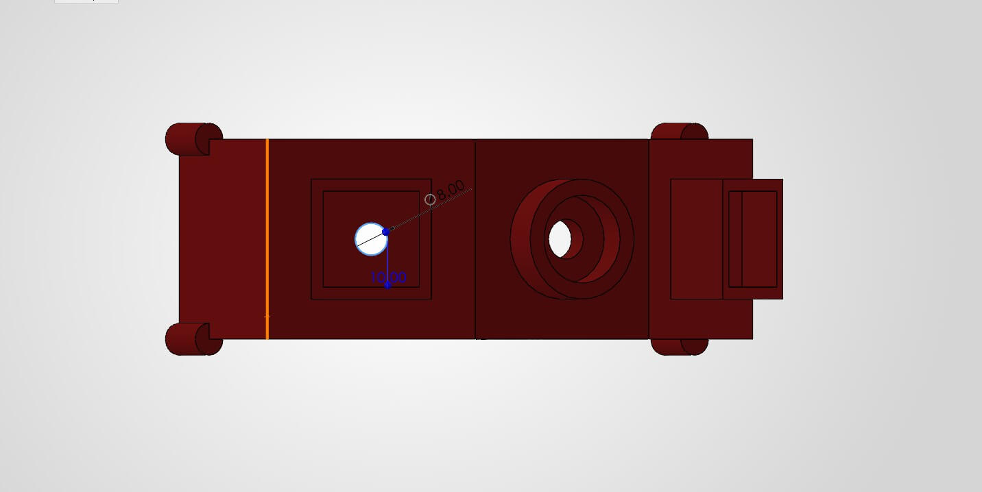
Adding secondary holes for cable routing.
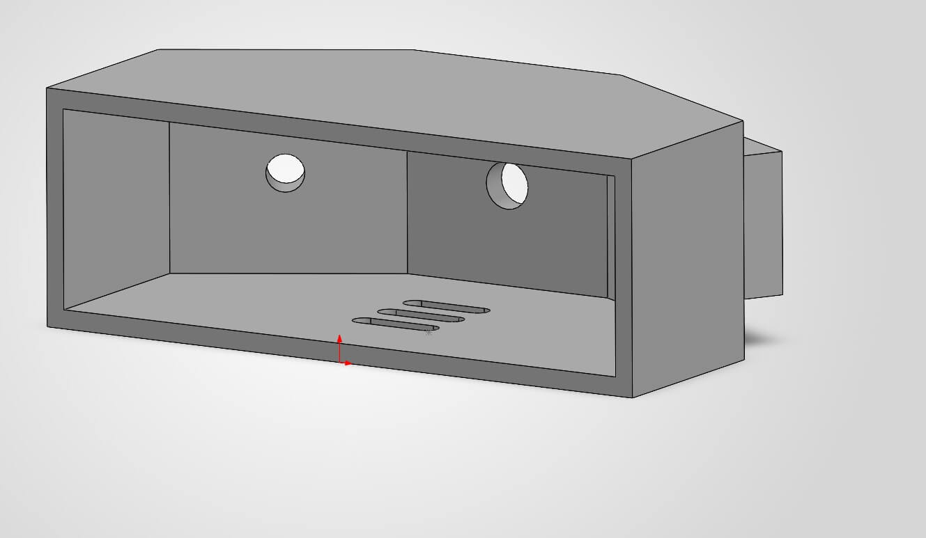
Current progress view of the semi-finished model.
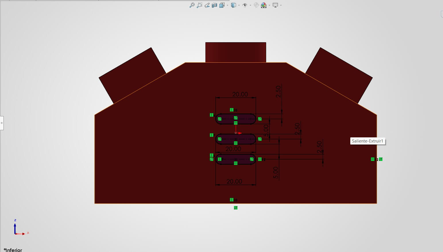
Designing ventilation slots (vents) to allow air circulation and prevent heat buildup from the battery.
Reviewing the final geometry before texturing.
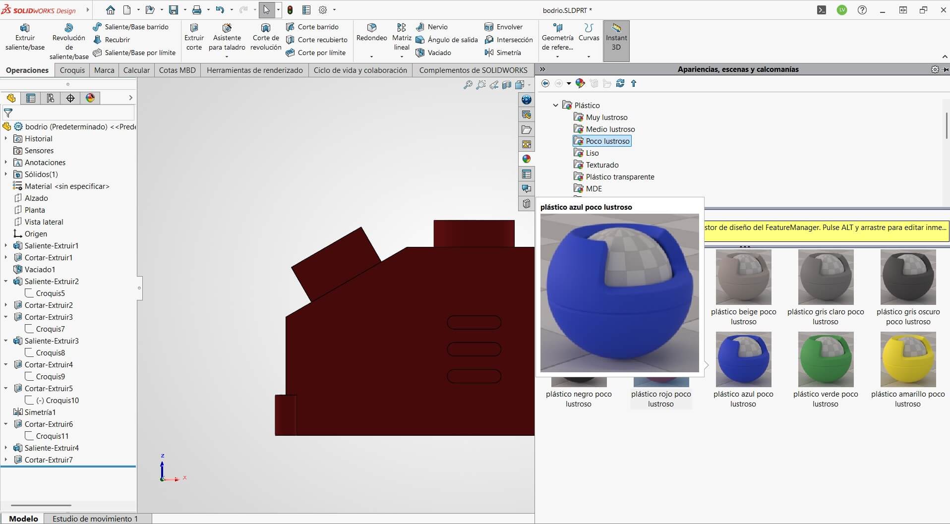
Opening the Appearance Manager to apply material properties.
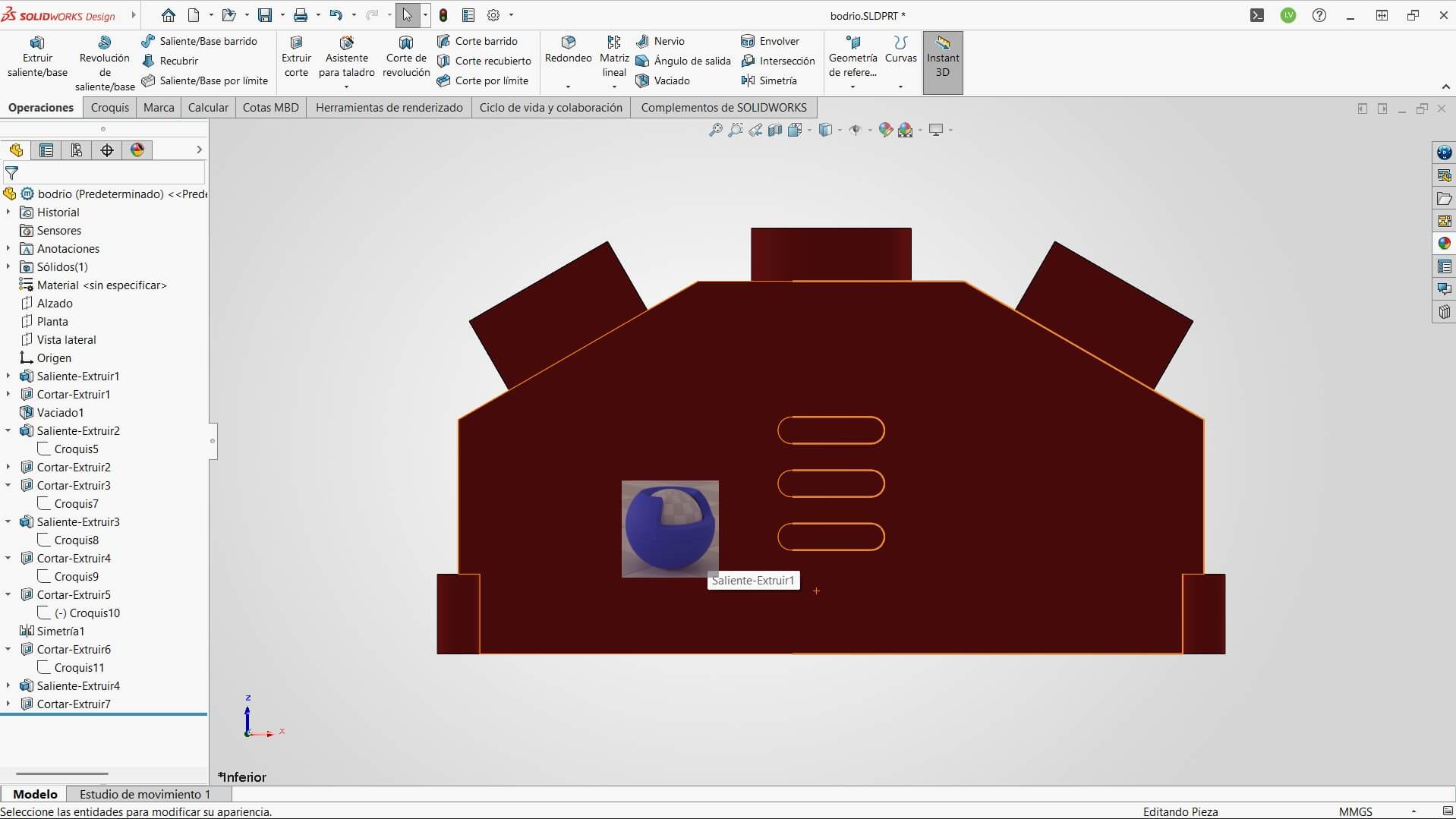
Applying the material by dragging the texture directly onto the solid body.
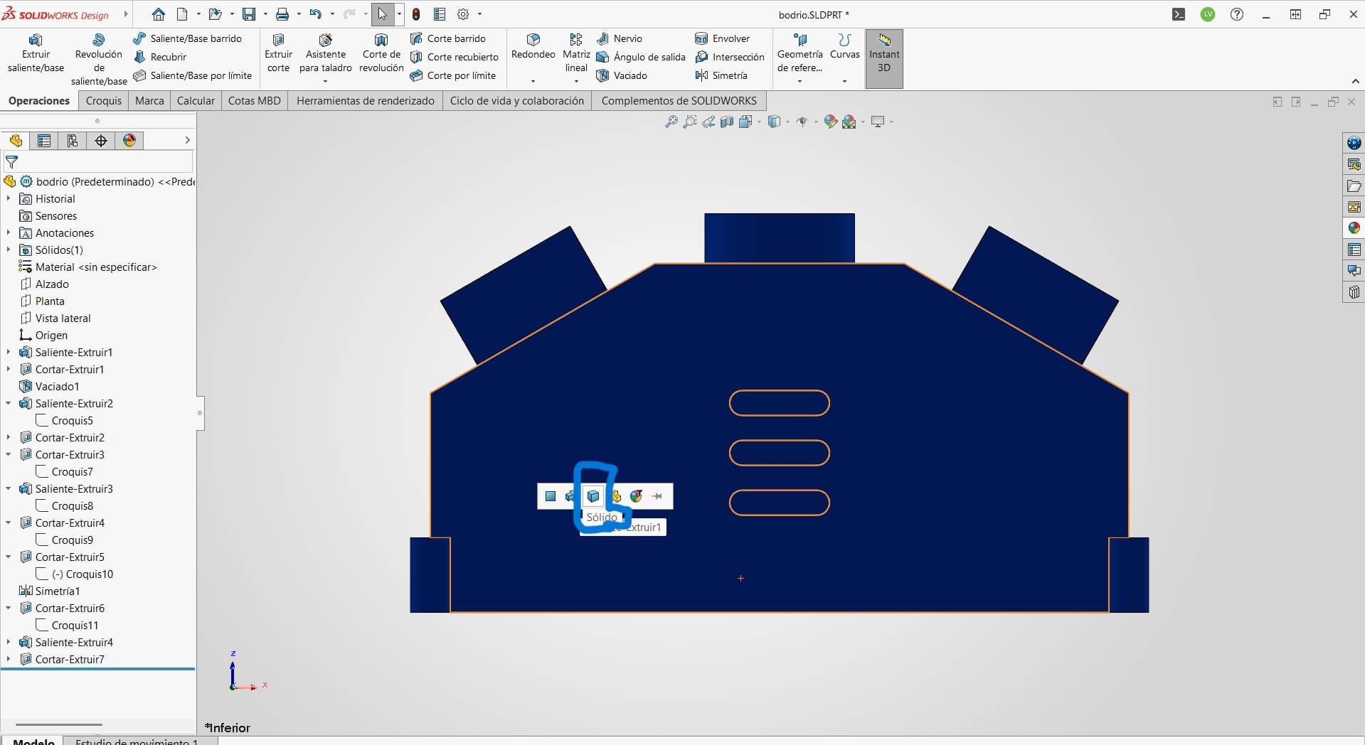
Selecting the entire part body to ensure uniform appearance application.
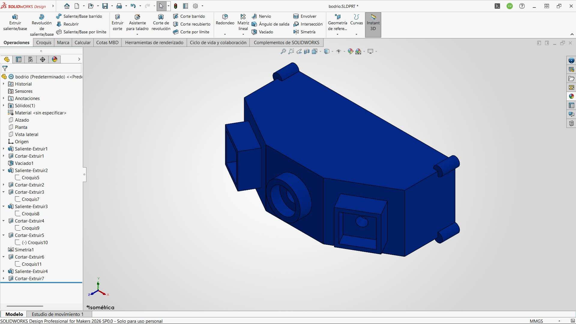
The Enclosure is ready for 3D printing!
It's not enough to just draw the part; I need to know if it will survive the real world and what it will look like.
My project is a Goal Sentinel, so it will inevitably get hit by a ball. I ran a Finite Element Analysis to ensure the enclosure won't crack.
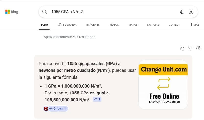
First, I researched the physics. I calculated the impact pressure generated by a soccer ball traveling at 80 km/h. I used this data to define the "External Load" in the simulation.
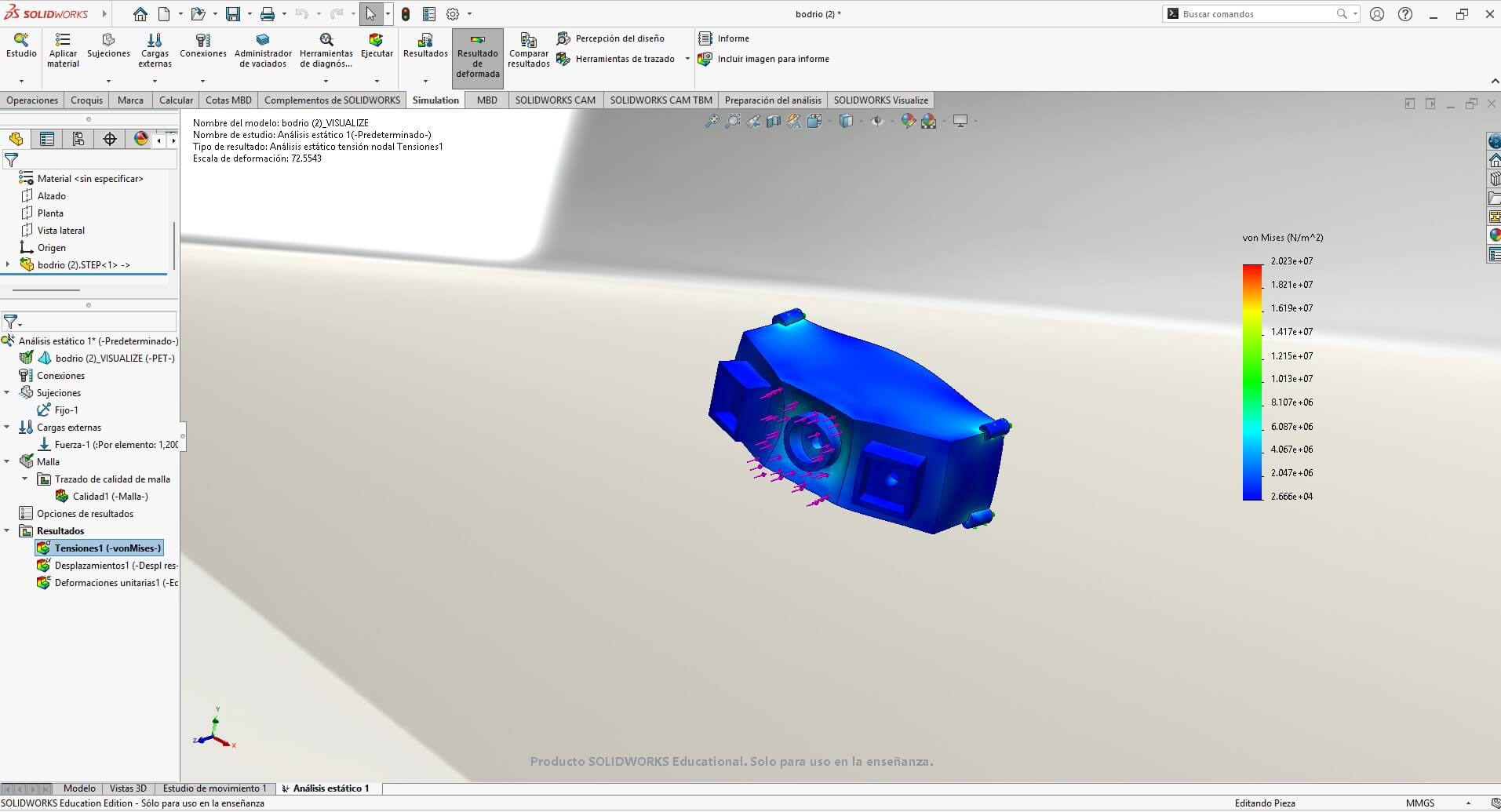
I set the material to PET Plastic (standard for 3D printing). The Von Mises stress analysis shows mostly blue areas, meaning the stress is low. The part will absorb the impact without breaking!
Finally, to visualize the final product for marketing and presentation, I used SolidWorks Visualize.
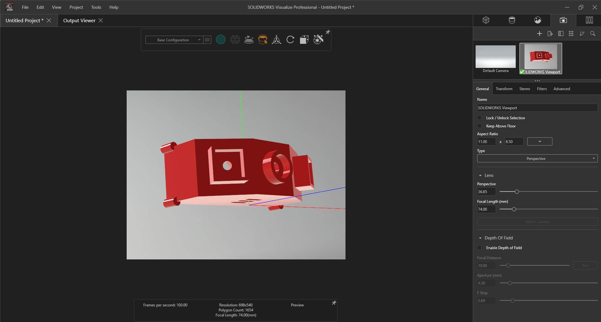
Inside Visualize, I set up a "Studio" environment. I adjusted the lights, camera focal length (74mm), and applied a glossy red plastic appearance.
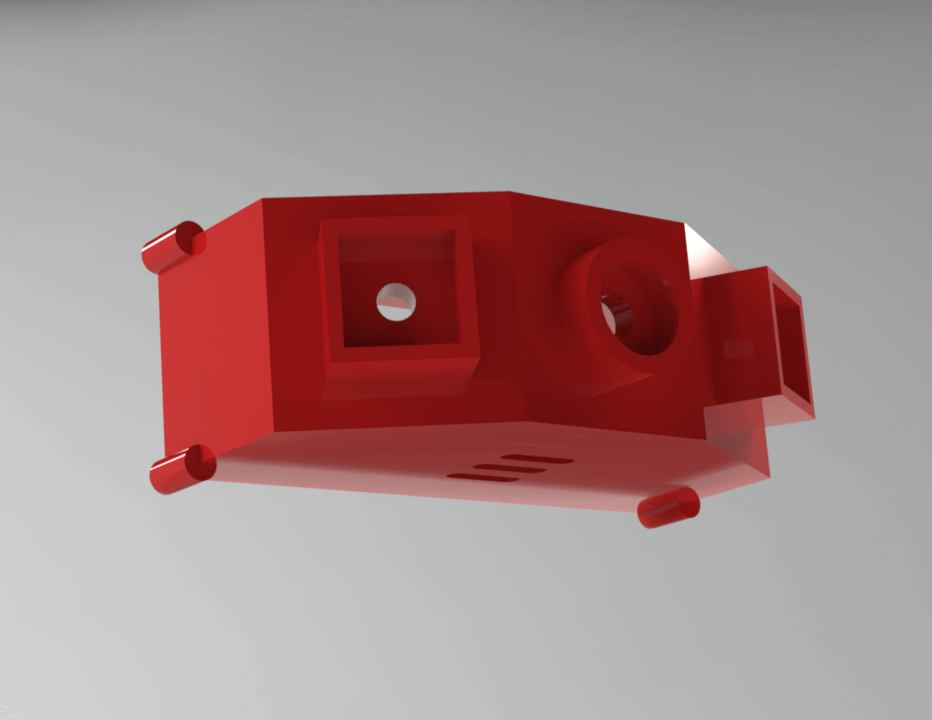
The Result: A photorealistic image of the Goal Sentinel. This helps to check surface imperfections and communicate the design intent before manufacturing.
During this week, I used Gemini as a technical assistant to troubleshoot errors and optimize my workflow. Here are the 3 key moments where AI saved the day:
"My sidebar disappeared and the 3D tab is taking up the whole width. Help me fix the structure."
The Fix: I had accidentally deleted a closing </div> tag when pasting the FFmpeg code. Gemini identified the "sandwich" error in the HTML structure.
"I'm trying to compress a video with FFmpeg but the terminal says command not found."
The Fix: Guided me through installing FFmpeg via winget and correcting the file path syntax errors in PowerShell.
"How can I auto-trace a color image in Affinity Designer like I did in Inkscape?"
The Insight: Gemini clarified that Affinity lacks a native "Auto-Trace" feature, confirming my decision to use Inkscape for quick conversions and Affinity for manual clean-up.
Here you can download all the source files generated during this week.